RCA CT-100 Color Television Design


If you haven't already read my CT-100
restoration article, I suggest that you start there. It chronicles
how I found a CT-100 and restored it to working condition. This
article discusses what's under the hood.
RCA CT-100 Color Television Design
The CT-100's 1954 product launch accompanied the birth of color TV broadcasting
and its electronic design closely follows the original USA color
standard.
After noting some hardware highlights, we'll discuss how the CT-100
decodes color, framing that in the context of
the NTSC standard. The article concludes with a library of key CT-100 documents,
including the factory service manual and the NTSC specification.
Here's a table of contents:
CT-100 Hardware Highlights
Chassis Overview
The 15GP22 Picture Tube
VHF-UHF Tuner
Field Neutralization
DC Restoration
How the RCA CT-100 Decodes Color
A Color System That Flopped
The NTSC Standard: Compatibility and Color Quality
New Roommate in the Black and White House
Three Modulation Methods
How Much Color Does Your Eye Need?
Hue and Saturation
What's Your Color IQ?
Sending Three Colors in Two Signals
Color Demodulation 1.0
Color Demodulation, CT-100 Style
Where Does Zero Start?
Color Demodulation 2.x
Whose Color Is "Best?"
RCA CT-100 Reference Library
RCA CT-100 Owner Manual
RCA CT-100 Service Clinic Manual
RCA CTC2 Service Manual T3
RCA CT-100 Field Service Manual
The CT-100 Commercial Color Television Receiver
Typical Color Television Receiver
The NTSC Color Television Standards
NTSC Signal Specifications
A VHF-UHF Television Turret Tuner
Practical Color Television for the Service Industry
Hoffman Color School, February 1954
Principles of Color Television, Hazeltine Laboratories
CT-100 Hardware Highlights
Chassis Overview
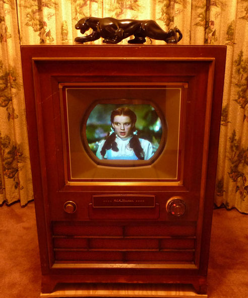
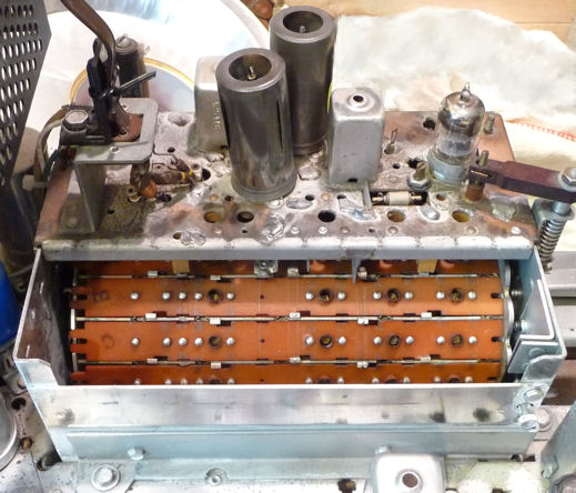
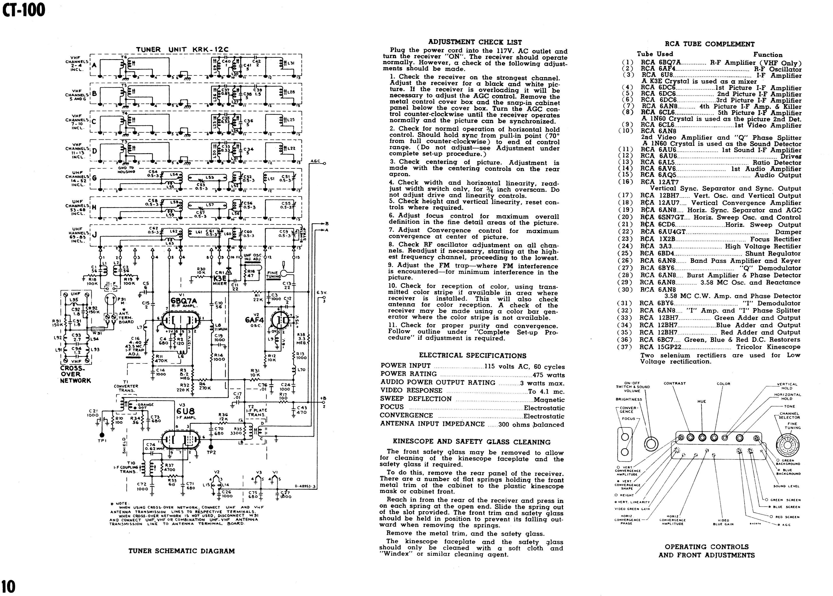
The CT-100 television is a complicated critter. It uses 37 tubes, including the 15GP22
tri-color picture tube. This diagram from the RCA service manual shows the
layout of tubes and controls. The photo shows my chassis during restoration.
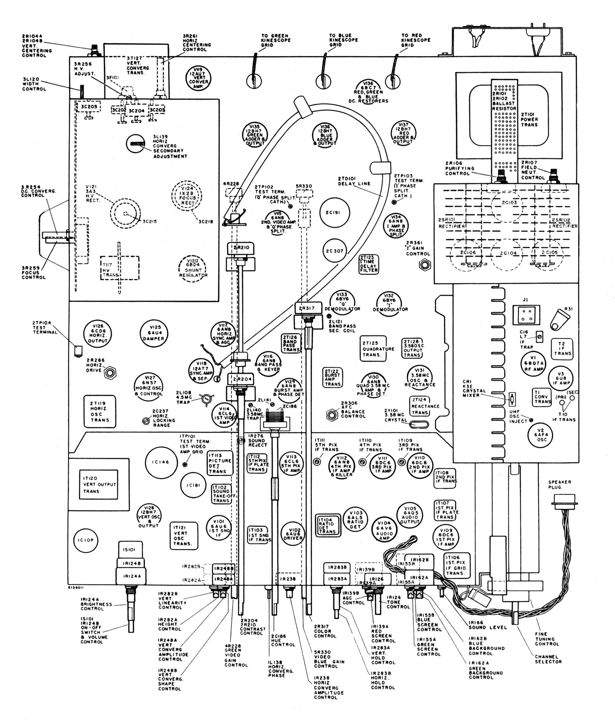
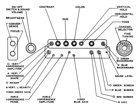
Here's a diagram of the CT-100's front and side controls. The previous
chassis layout diagram shows additional service adjusters on the top and
rear of the chassis.
You might be a little surprised to hear that the CT-100 contains solid-state
components. It actually uses five of them: two selenium rectifiers for the
low-voltage power supply and three crystal diodes for the RF mixer,
audio detector, and video detector. My 1940s televisions use tubes for
all of those functions. Had the CT-100 followed suit, its tube-count would
have topped forty!
The 15GP22 Color Picture Tube
The CT-100's 15GP22 picture tube is both rare and
complex. Few were produced in the first place, and of the few
survivors, many have lost vacuum, relegating them to
the netherworld of duds. It is not possible to substitute any
other tube without making modifications that would destroy the
authenticity of the CT-100.
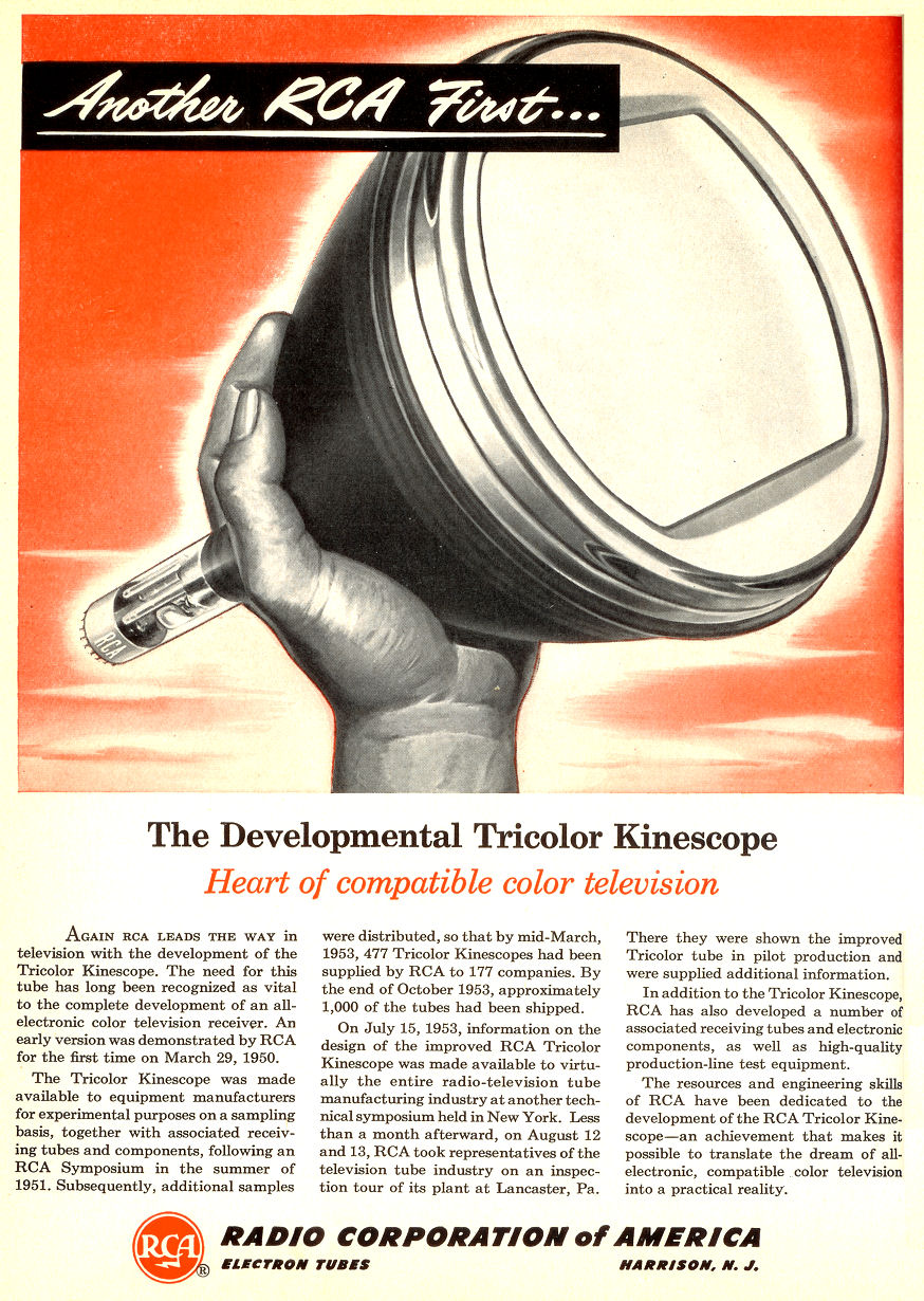
This 1954 ad describes the tube's introduction (click to see a larger version):
This was a very expensive tube. The 1955 Radio Shack catalog lists the 15GP22 for $235, at
a time when most picture tubes cost under $50.
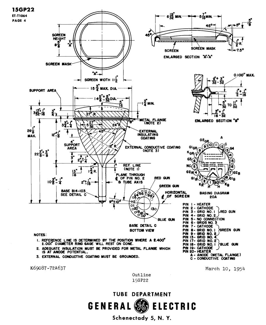
The 15GP22 had a short service life, and at this writing
nobody in the world has a commercial process for rebuilding
it. Here's a page from its
data sheet:
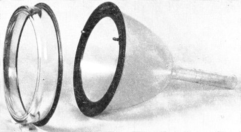
In many picture tubes, the envelope is a single glass piece,
like a light bulb. In the 15GP22, the face and the body are separate glass
pieces bonded to a metal flange, or ultor ring. This picture shows the
two glass parts with metal rings attached:
Mounted inside is a multi-part screen assembly with a mask
that matches the rectangular mask in the cabinet.

Beams from the CRT's electron guns pass through holes in the shadow
mask and strike phosphor dots on the glass plate, illuminating them.
High precision was needed to fabricate these parts and mount them
in alignment.
Metal and glass have different expansion coefficients, and the manufacturing
process took special care with heating and cooling cycles
to avoid (among other things) breaking the glass phospor-dot plate held
in its metal frame.
Many details of the 15GP22 manufacturing process are given in the
article Improvements in the RCA Three-Beam Shadow-Mask Color Kinescope,
from the January, 1954 issue of I.R.E. Proceedings.
The two previous photos appear in that article.
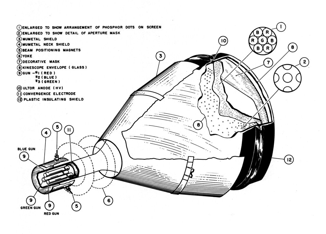
This diagram shows more internal features and the external
mu-metal shield
and insulating gasket (click to see a larger version):
Yet another description of 15GP22 manufacturing appeared in
the November, 1953
issue of Popular Science.
15GP22 Rebuilding Attempts
Many picture tubes can easily be rebuilt by substituting a new electron gun assembly.
This is not true for the 15GP22, and the unavailability of rebuilding
makes every good 15GP22 even more valuable.
The Achilles' heel of the tube is the double glass-to-metal bond
between the flange rings and glass envelope parts. If that bond fails
anywhere, air leaks into the tube and ruins it. Further, the two metal flange
parts are machine-welded together around their perimeters, and that weld is another
potential source of leaks.
For more than ten years, dedicated TV restorers including John Folsom and
Bob Galanter worked to develop a process for rebuilding a 15GP22 tube.
Late in 2009, the team announced their
first successful rebuild—a real achievement. In early 2010,
they had a setback when two candidate tubes failed during
a rebuild trial. Each tube failed in a different way. One lost
vacuum after their best attempts to seal it. Another suffered
a cracked stem in the oven. The team suspended their project
pending further research.
Also during 2009-2010, Jerome Halphen in Paris consulted with the French
company RACS and brought them a candidate tube for rebuilding. After coating a
leaky area with frit glass, RACS rebuilt the tube and it was
demonstrated
at the 2010 Early Television Foundation convention. This experimental rebuild was
encouraging, but the RACS company—the last commercial rebuilder in the world—went
out of business in 2013. The ETF purchased the RACS equipment and launched a
project to
rebuild tubes in Ohio, but that effort is probably years away from completion.
The moral of the story: if you have a working 15GP22, take good care
of it!
VHF-UHF Tuner
Another little surprise is that the CT-100 can receive
UHF (ultra-high frequency) as well as VHF broadcasts.
UHF broadcasting was not widespread in 1954, but it did exist.
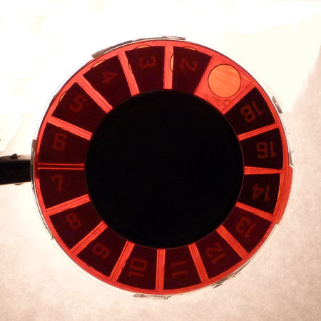
The CT-100's turret-style tuner has sixteen positions. Each position could be set
to receive a VHF channel (2-13) or UHF channel (14-83). For a new CT-100,
the dealer would set it up to receive the channels in that locality. Mechanically,
this was done by inserting a "channel strip" for each desired channel
in the tuner.
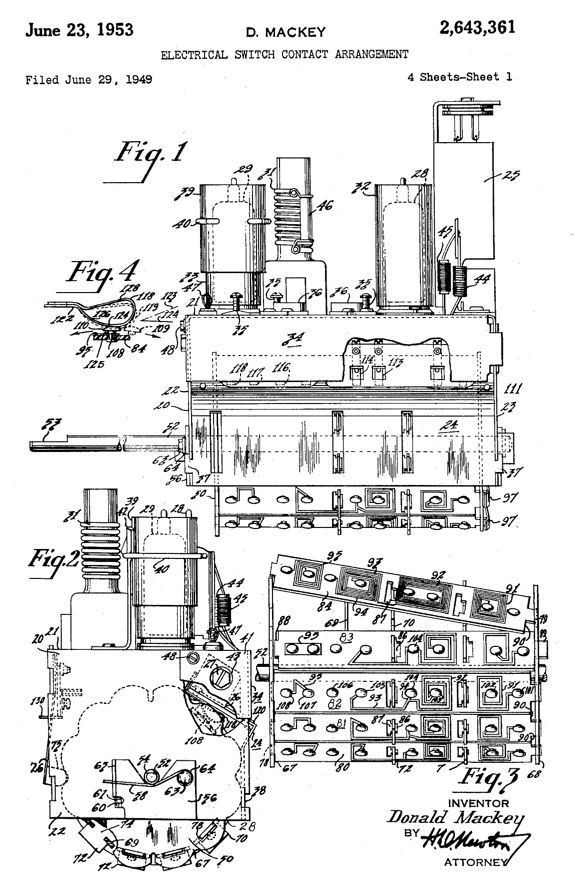
A drawing from RCA patent
2,643,361 shows
a tuner of this general type. The strips (Fig. 3) can be popped in and out of
the rotating turret assembly. The photo shows strips in the CT-100 tuner.

The channel indicator came from the factory showing the standard
twelve VHF channels plus four UHF positions. My CT-100 was set up for VHF channels
2-13 plus UHF channels 14, 16, and 18. My restoration
article has more about this indicator.

Why only sixteen channels?
Many early sets such as my National
TV-7W had tuners that selected fewer than twelve VHF channels. Although the VHF band included
channels 2-13, the FCC limited the number of stations in any given locale to
a maximum of eight. It put further limits on adjacent channels to minimize interference.
In practice, the biggest US cities such as New York might have six or seven VHF
channels; smaller cities and towns had fewer.
UHF broadcasting was even more limited because that market was poorly
developed. In 1954, a major city
might have a couple of UHF stations, but vast areas of the USA had none. All-channel
UHF tuners were almost unheard-of in the 1950s. They did not become common until
1965, when the FCC forced manufacturers to put them in every new TV.
With sixteen possible channels, the CT-100 tuner was adequate for 1954.
Its only drawback was that if you moved to a new town, you might need to have
the dealer adjust the tuner to different channels.
In the library below, you'll find a detailed article,
A VHF-UHF Television Turret Tuner.
Written by RCA engineers, it analyzes all of the tuner
circuits and gives the results of extensive field testing.
Field Neutralization
The CT-100 has one gizmo, the "field neutralization coil," that I haven't
seen on other TVs. It is a simple coil that goes around the front of the picture
tube and is controlled by an adjuster on the back of the low-voltage power supply
cabinet.
At first glance, I mistook this for a built-in manual degausser. Newer color TVs
have a built-in automatic degausser, also a simple coil around the CRT face, which
briefly energizes each time you turn on the TV. This lets you move the TV
in your house without having to manually degauss the set to counteract the
change of position within Earth's magnetic field.
The field neutralization coil is actually used to adjust purity around
the CRT edges when you are going through setup routines. You can read more
about purity adjustments and the field neutralization coil in my restoration
article.
DC Restoration
DC restoration affects the TV's ability to maintain correct black levels in
scenes with high contrast. Better-quality black and white
TVs like my DuMont RA-103 have a
separate DC restoration circuit, but cheaper sets do not. In a TV without DC restoration,
if you set the brightness and contrast for good black levels in bright scenes
with high contrast, the overall picture may be too dark in darker scenes with
high contrast.
The CT-100 has a separate stage of DC restoration for the Red, Green, and Blue
signals produced in the TV's color matrix/output section. Later color TVs such
as my 1961 CTC-11
omit this stage.
Several sections of the CT-100 are pretty conventional for the mid-1950s
and will not be discussed here. These include
the power supplies (low and high voltage), RF and IF amplifiers, and horizontal
and vertical sweep. You can find details about those
sections in the technical library below, particularly
the RCA service manual and Grob's description of the CT-100.
Some people ask whether the CT-100 resembles a prototype, slapped
together in a hurry. The answer is No. The CTC-2 chassis clearly evolved
from earlier proven designs, such as the much-imitated
630TS. You can also trace a clear
evolution from this to subsequent RCA color chassis: the CTC-3, CTC-4, and so forth.
In some ways, a later chassis like my CTC-11 was a dumbing-down of this
design, cheaper to build and simpler to service,
with no DC restoration, three video IF stages rather than five, X-Y
rather than I-Q demodulation, and a wafer tuner rather than a turret.
It's hard to blame RCA for economizing when their color TV
cost as much as a new car. I have heard that no TV manufacturer made money
from color until well into the 1960s, when color programming
became popular.
How the RCA CT-100 Decodes Color
The bulk of this article describes what you might call the heart of the CT-100,
its color decoder, or "demodulator." I won't try to describe the color
circuits fully; the references in the library section do that.
Since the CT-100 arrived at the same time as the new NTSC color system,
we'll review them together, beginning with the NTSC standard's origin
and an even earlier system that didn't succeed.
A Color System That Flopped
Some people don't know this, but our current color broadcasting system was
not the first one attempted in the USA.
In the late 1940s, TV companies had proposed various schemes for color, using mirrors,
lenses, and even triple picture tubes. CBS was first off the drawing board
with its "field sequential" system that used a spinning disk with red, green,
and blue filters in front of a black and white picture tube. This system was
given a brief national trial in 1951.
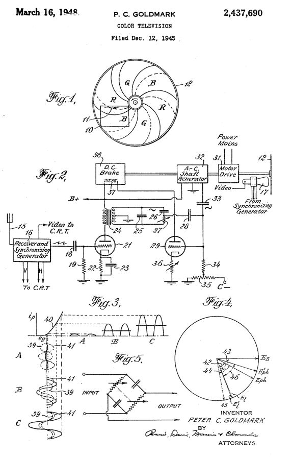
The CBS scheme smacked a bit of Rube Goldberg. Spinning disks are subject to wear
and breakdown, and if the disk speed was not perfectly synchronized, the color would
degrade. CBS obtained various patents relating to this system. Here's one diagram:
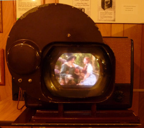
This system could produce nice color under optimum circumstances.
I took this photo at the 2010 Early Television Foundation convention.
It shows an RCA black and white TV similar to my
T-100 using a
CBS
color converter.
This adapter uses a magnifying lens and a separate control box that's hard-wired
into the TV's circuitry.

Incompatibility was a major drawback of the CBS system. Tens of
millions of people who owned black and white TVs couldn't view a
program broadcast in color without buying or building a separate gizmo like this one.
Lower resolution was another problem. This system displayed only 405
lines of video rather than the standard 525 lines. It
also had problems with flicker and portrayal of fast-moving objects.
After the 1951 trial, the CBS system was abandoned. You can learn much more about
early color development from
the Early Television Foundation.
The NTSC Standard: Compatibility and Color Quality
On the heels of the CBS failure, the National Television
System Committee (NTSC) forged a new color standard compatible with existing
black and white broadcasts. The FCC gave this specification the force of law in
December, 1953. The CT-100 reached RCA dealers four months later, in April, 1954
Henceforth, owners of either kind of TV could view all broadcasts. Color TV owners
would see color when a color program was shown, and black and white for other
programs. Black and white TV owners would see everything in black and white.
This solution, which we take for granted today, preserved the investment of millions of TV owners
and avoided massive duplication of infrastructure for broadcasters,
manufacturers, and dealers.
The NTSC standard has ruled for more than 50 years throughout the US and much
of the Americas (other countries use schemes called PAL and SECAM).
Although the US converted from analog to digital TV broadcasting in 2009, the
standard remains part of US law. NTSC color also lives on in countless NTSC-format DVDs
and other recordings, of course, and with a home
TV transmitter like mine, you can broadcast any NTSC content you choose,
including live TV relayed from cable or a digital converter.
The reference library at the end of this article includes two
seminal NTSC documents:
The I.R.E. Proceedings issue cited earlier contains much more NTSC information.
New Roommate in the Black and White House
The compatibility mandate was a boon for TV watchers but it made
life tricky for color engineers. The black and white television standard
had not been designed for future expansion, and consequently
the existing VHF channels (2-13) were already pretty full of information for
black and white video and audio.
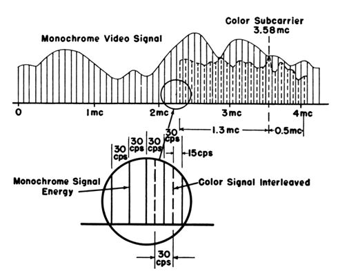
Each channel was 6 megahertz (MHz) wide. Channel 3 was located from 60-66 MHz,
channel 4 from 66-72 MHz, and so on. The challenge was to shoehorn extra color
information into that same 6-MHz signal space without making a black and
white program look strange.
This was done by including the color information in a subcarrier signal
"concealed within" the main picture signal. Here's one way
to visualize it.
Like a kid with a secret decoder ring,
a color TV has extra circuits to demodulate (decode) the color information.
A black and white TV lacks these special demodulator circuits and displays the
picture the only way that it can: in monochrome.
The analogy of a new roommate—one who doesn't pay rent—is
apt in a couple of ways. The extra roomie must fit into the house somewhere, but never
be seen by the landlord. Perhaps he hides in the attic, or, like
someone in a Marx brothers movie, flits from room to room as the
landlord walks around, always escaping detection.
The new roomie must also behave himself, not throwing wild
parties or punching holes in the wall.
Similarly, while the color signal is always present, it must never
be "seen" by a black and white TV. It
must not create strange patterns in the video
or weird noise in the audio.
If these two considerations—fitting into the available
space, and non-interference—were not at play, color TV
technology would be simpler. Much of its complexity
grows from the need to pack color
information into the smallest possible space and cleverly encode
color signals to avoid disrupting the main picture signal.
Three Modulation Methods
A color TV signal contains three kinds of information—the
monochrome video image, the sound, and the color—which are
sent with three different modulation methods: AM, FM, and subcarrier
timing differences.
| Information |
Method |
| Video image |
Amplitude Modulation (AM) |
| Sound |
Frequency Modulation (FM) |
| Color |
Subcarrier Timing |
AM and FM are familiar from the radio world.
AM uses a fixed frequency and a changing amplitude.
This was shown as the vertical rise and fall of a signal
in the previous diagram. FM has a fixed amplitude and
changing frequency, the opposite of AM.
The color hue is defined by the timing difference between the color subcarriers.
This is expressed by their relative phase, which can fall between 0° and 360°.
Diagrams showing phase modulation often employ circles, but
you can also show angular relationships in a graph. In this
diagram, the signals (sine waves) A and B have the same amplitude
and frequency, but they're 45° out of phase.
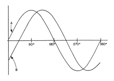
This diagram doesn't show a color signal, but you get the general idea
that two signals can have a phase, or angular, relationship.
The complete color signal is actually sent with
two methods—AM modulation and timing (phase) differences—as we'll see momentarily.
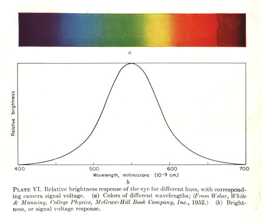
How Much Color Does Your Eye Need?
The NTSC engineers faced a daunting problem
in deciding how to squeeze color information into a
crowded space. One part of the solution exploits the
way that our eyes perceive color, illustrated by the
NTSC pennant:
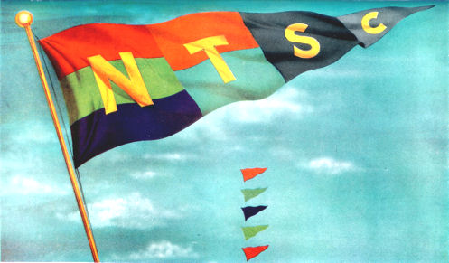
I scanned this image from a color plate in the Bernard Grob book mentioned
later in this article. Its 56-year old colors have faded a bit (ironic, eh?), but you
can grasp the idea.
The big left bars on the pennant show Red, Green, and Blue, the familiar
R-G-B used to create all colors in this system. Had compatibility (and
thus bandwidth) not been an issue, engineers could simply have transmitted
three primary color signals in the TV broadcast. Limited bandwidth
disallowed such luxuries and forced them to cram maximum information into the
smallest possible space.
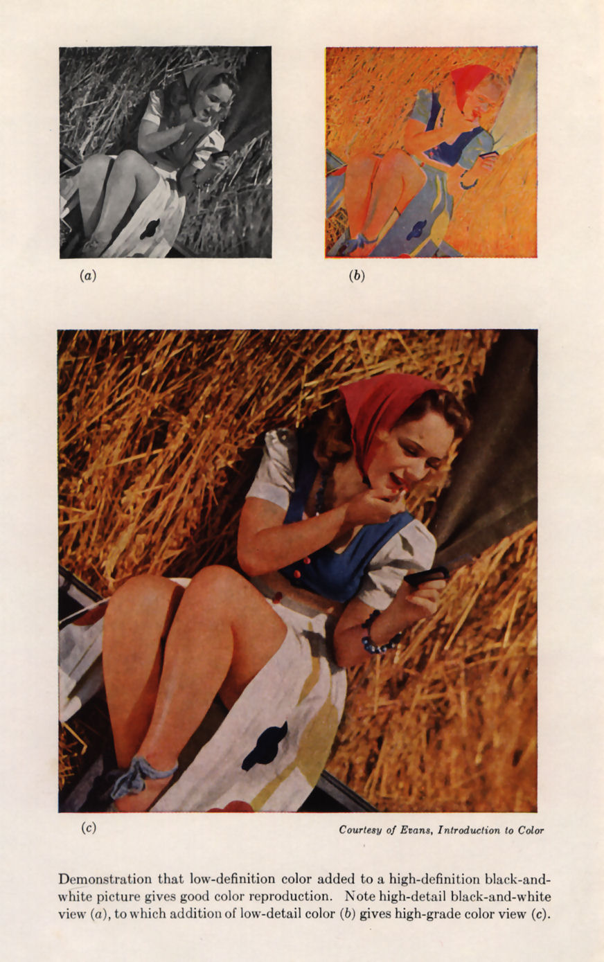
Fortunately, some parts of a color scene don't need to be shown in
three colors. The smaller the detail, the fewer distinctions among hues the eye
can perceive, and therefore less color information is needed. Here's how
NTSC breaks it down:
- Large color areas are shown with full three-color reproduction.
- Smaller color areas are shown with only two colors (here, orange and cyan).
- The tiniest details are shown only in black and white.
To portray this idea, the smaller middle bars of the pennant show only two colors, orange
and cyan. The smallest parts at the end are shown in shades of gray to
signify black and white.
The five little pennants have no technical meaning.
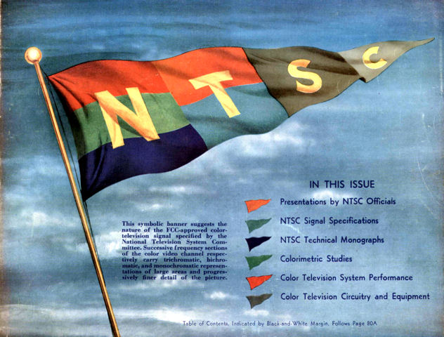
In the cover art for the I.R.E. Proceedings
magazine mentioned above, the pennants highlighted the contents:
The caption is worth quoting: This symbolic banner suggests the nature of the FCC-approved
color-television signal specified by the National Television System Committee. Successive
frequency sections of the color video channel respectively carry trichromatic,
bichromatic, and monochromatic representations of large areas and progressively
finer detail of the picture.
In sum, the NTSC standard provides the highest level of information for colors
that the human eye perceives most acutely.
Hue and Saturation
For color broadcasting, the term "color" is not precise enough. The science
of color was well advanced in the 1950s, resulting from years of research
into photography and color printing. Scientists use two terms,
hue and saturation, to define what we call color in everyday language.
The hue of an object is what everyone calls its color. A green leaf has a
green hue. A yellow sun has a yellow hue.
Saturation defines the intensity of a given hue, specifically, the
proportion of its mixture with white light. A pure (100% saturated) green light
is very intense. If you mix that green with 50% white light, it has the same hue
but lower saturation, and thus lower intensity. If you
look at color samples in a paint store, this is very evident. The same hue can be found in
many saturations, ranging from very intense—highly saturated—to a faint tint with low saturation.
The mathematical relationship of hue and saturation appears in the well-known
chromaticity diagram published in 1931 by the CIE (Commission internationale de l'éclairage,
or International Commission on Illumination).
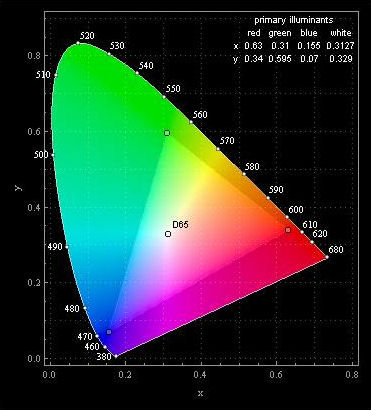
In this diagram, white light occupies the center, with red, green, and
blue at the periphery. The colors are plotted on a graph with X and Y
axes. Saturation is highest at the outer edges and it becomes lower
as you approach the white center. Thus, any
color—a hue value and saturation value—can be
defined with two numbers for X and Y.
Color broadcasting uses this concept, sending hue and saturation as a
pair of color signals for every dot on the picture tube. Both signals are
transmitted in the color subcarrier, but with different modulation methods.
Hue is sent with phase modulation (PM) and saturation with amplitude
modulation (AM). This scheme is compact and minimizes interference with
other signals.
What's Your Color IQ?
If you read about color broadcasting, including the NTSC references
and book chapter in our library, you'll run across two mysterious
values named I and Q. These are the color signals
sent by the TV transmitter, but what do they stand for, exactly?
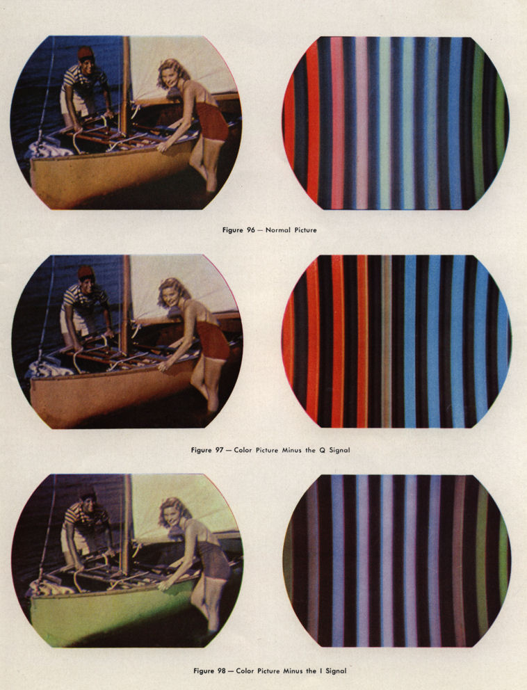
Let's look at a couple of pictures. These come from the
Grob book referenced below, but I added a
little color to make them easier to follow.
Referring back to the previous diagram, imagine that we plot the
color spectrum around a circle rather than an irregular spade shape,
and that we add an arrow to represent a specific color.
It might look like this (notice the location of Green,
Red, and Blue primaries in both diagrams):
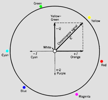
The axes in this circle are named I and Q and
they have negative and positive values.
Equidistant around the circle are three primary colors: Green, Red, and Blue.
At midway points between the primaries are their complimentary colors: Yellow,
Magenta, and Cyan. It's the same general scheme as in the chromaticity
diagram, with white at the center, so that colors farthest from
the center have the highest saturation, while those near the center
have low saturation.
Here, the arrow labeled Chrominance Signal C points at
Yellow. Its angle signifies the yellow hue. If
Chrominance pointed at Red, that angle would mean
the red hue.
The length of the Chrominance arrow—its distance from the white center
point—defines the color's saturation. If the arrow's
point reached all the way to the yellow spot, that would
indicate 100% saturation (all yellow, zero white). A shorter arrow pointing at the same
angle would indicate lower saturation (less yellow, more white).
These examples show how you could plot various colors
on this circle, starting with the same hue, yellow:
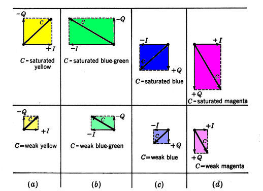
Example (a) shows two flavors of yellow, with longer and shorter arrows
representing that hue with higher and lower saturation. The others
show high and low saturation for three
more colors: blue-green, blue, and magenta.
In math, these sorts of arrows are called vectors,
meaning that they define a strength or magnitude
(here, saturation) in addition to an angular direction (here, hue).
Color broadcasting uses vector math, in short, but that doesn't
explain why we're using I and Q rather than
some other values like X or Y.
This question brings us back to the NSTC pennant, which
teaches that smaller color areas can be shown using only two hues: orange
and cyan. Now look back at our color circle and notice
which hues are identified with I.
Ta-da! The hues on the I axis are orange and cyan.
The hues on the Q axis are complimentary: green and purple.
The placement of the I axis on the color circle
allots the largest amount of bandwidth to the orange-cyan range of hues,
fulfilling the goal expressed in the NTSC pennant.
Within the limited space available for color information,
only the I signal is permitted to use the entire 1.5-MHz bandwidth,
and it covers the range of hues to which our eyes are most responsive.
In case you're wondering where the names come from,
notice that I and Q are
shown 90° apart. The name I means "in phase"
and Q means "in quadrature," a relationship
that's used in the decoding math.
Sending Three Colors in Two Signals
Speaking of R-G-B, a tricolor picture tube requires
three separate voltages—one for each primary color—to
reproduce the desired color on a dot on the screen.
How do we get from the I-Q pair to
the R-G-B triad?
Let's start with the color transmitter, which, in simplest form,
is a mirror image of the TV receiver. Because bandwidth
was limited, engineers used clever math to send the
information for three colors using only two color signals.
Here's a sketch of a color TV camera and transmitter:
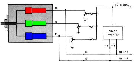
The color TV camera has three detectors, one for each R-G-B primary color. Whereas
an old-fashioned black and white camera detects a single brightness value,
here we combine three color signals into a luminance value
that engineers call the Y signal. (Don't confuse this Y with the
color yellow.) At the upper right, you can see the Y signal being
sent off for transmission to everyone's color TV.
The rest of the diagram shows how color information is processed. Rather than
primary color values, we send color-difference values,
which are the difference between a primary color and the luminance.
To enable the math, we invert (make negative) the Y value.
At lower right in the diagram, you can see the color-difference signals that are sent:
- R-Y, the difference between Red and Luminance.
- B-Y, the difference between Blue and Luminance.
That accounts for Red and Blue, but what about Green? Here comes
the clever bit:
There's no need to transmit a Green color signal
because, once you know the luminance and the two color-difference
values, you can simply calculate the missing G-Y value.
Three colors for the bandwidth of two!
The calculation uses ratios from color science, which learned
that the human eye is most responsive to the green part of
the spectrum.
Pure white light is comprised of the following proportions of red, green, and
blue light, and the transmitter uses these ratios when it computes
values for Y, R-Y, and B-Y:
- 30 percent Red
- 59 percent Green
- 11 percent Blue
If you prefer equations, here's how the NTSC specification
defines the relationship:
EY´ = 0.30ER´ + 0.59EG´ + 0.11EB´
After the TV receiver extracts those values from the signal, it
uses these ratios to compute the value of G-Y,
thus completing the R-G-B triad.
Color Demodulation 1.0
Conceptually, color decoding is simple. Looking back at the transmitter
diagram, you can flip it horizontally and picture everything in
reverse. Imagined as a color TV, the device would receive three signals and demodulate
(decode) them into R-G-B values to be sent to the picture tube.
That is, the TV could receive these:
- The Y luminance signal
- The R-Y color-difference signal
- The B-Y color-difference signal
If you stopped there, you'd have a system that worked, but the
NTSC specification goes farther, optimizing the available bandwidth
to match human color perception.
Thus, a real-world color transmitter does a conversion on the
color-difference values and sends the I and Q
values instead, transmitting:
- The Y luminance signal
- The I signal
- The Q signal
Converting these into R-G-B values involves fancy math, and for
those details I'll refer you to our reference
library below.
For the moment, let's just note that the TV
does the conversion in two steps.
- First, it creates color-difference values, R-Y, G-Y, and B-Y.
- Then it converts the color-difference values into R-G-B voltages.
To see this at play in the CT-100 television, here's a block diagram from the Grob book:
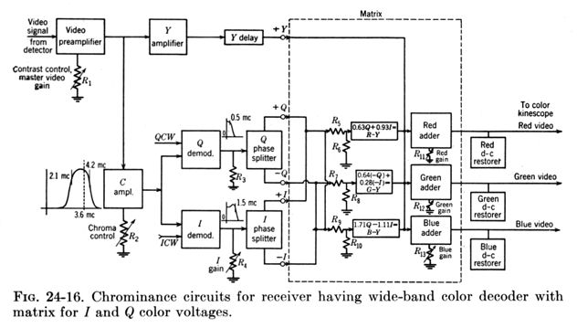
This is more complex than the simple transmitter diagram, but we can follow
our signals through the TV. Once again, our friend Y (luminance) appears at the top.
At far right, the final R-G-B signals are sent to the picture tube
("kinescope").
The rest shows how color is decoded, using the same terms as the
color circle diagram. From left to right, the value
C (as in "C ampl.") means chrominance, or the total color
information encoded in the TV signal. That goes to two
demodulators labeled I and Q. Their values are split into
positive and negative complements ( +I and -I, +Q and -Q)
by two phase splitters.
These four values, along with Y luminance, are shipped off into
the dotted-line box labeled Matrix, which combines them
to form the three color-difference values: R-Y, G-Y,
and B-Y. Different combinations produce different color-difference
values. For example, combining +I and +Q makes R-Y.
The Adder boxes add Y luminance to the color-difference values to
make Red, Green, and Blue for the picture tube.
We can also see the DC restoration stage mentioned earlier; note
the boxes labeled "d-c restorer."
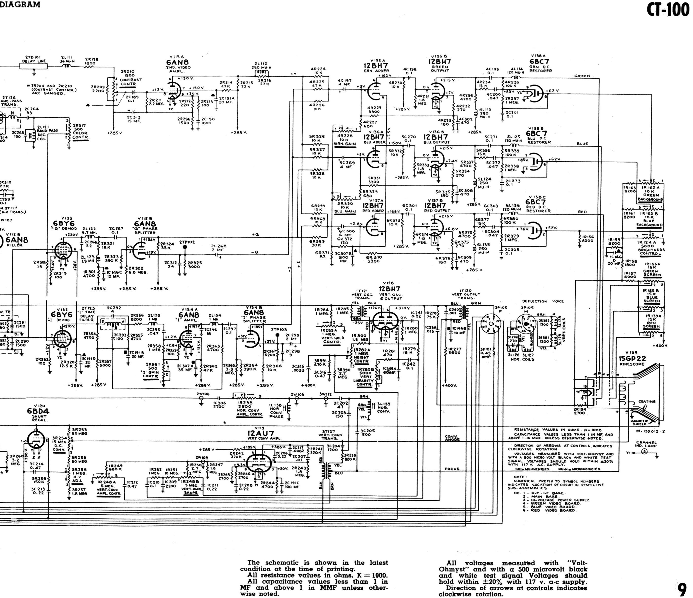
Color Demodulation, CT-100 Style
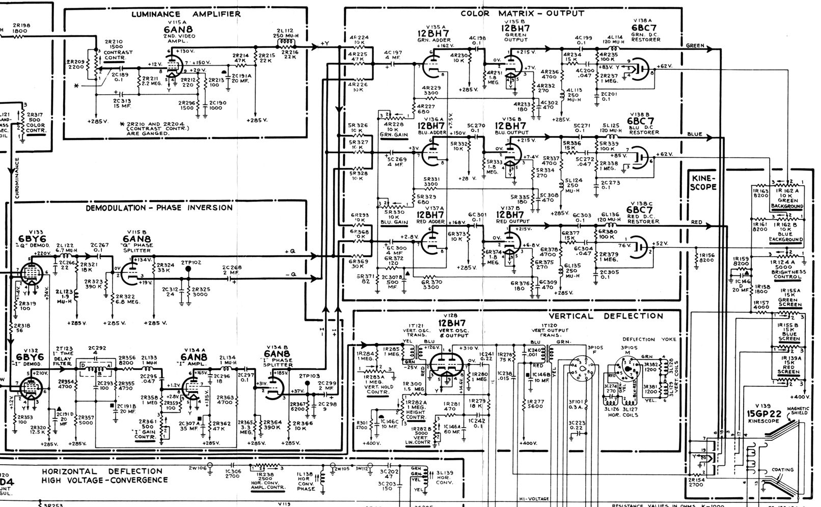
The previous diagram isn't mere theory. Here are the
demodulator and color matrix sections of the CT-100 schematic:
Just as advertised, the CT-100 extracts positive and negative values of
I and Q from the chrominance signal C.
The Y luminance comes from the luminance amplifier at upper left.
These five voltages are sent to the color matrix
where they are processed into R-G-B for the 15GP22 picture tube. DC
restoration is performed by three parts of the 6BC7 tube.
Where Does Zero Start?
The color circle showed that I and Q
have a 90° (quadrature) relationship, and we also learned that
phase modulation uses angles.
To use an angle, however, you need know its zero point.
In addition to color information, the color TV signal has a
portion called the "color burst." It defines the
reference phase, or zero point, used to calculate the needed angles.
In the NTSC specification below, the color burst is diagrammed as Figure 1.5.
You are probably familiar with horizontal and vertical synchronization,
in which external pulses—horizontal and vertical—are
used to keep the TV's local oscillators in sync with the broadcast content.
The color burst signal is unique to color broadcasts and it serves a
similar purpose, keeping the TV's local color oscillator in sync
with the broadcast.
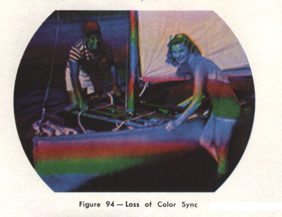
If a TV has a color phasing problem, the black and
white video image looks normal but the colors are messed up.
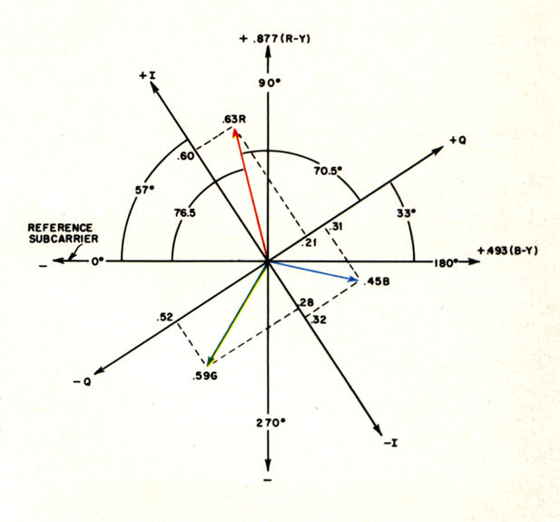
The zero point for color phasing is shown in another
picture from the Grob book, illustrating how I and Q
plot onto the CIE chromaticity diagram.
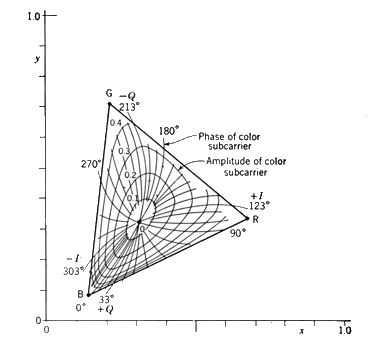
The center point, again, represents white, with hues shown as
radiating lines and saturations shown as concentric
enclosing lines. Colors of highest saturation appear at the outer
edges, just as in the earlier chromaticity diagram and color circle.
Starting from the 0° point at lower left, you can see that I and Q
are offset from the reference phase but in quadrature with
one another. Thus, +Q is at 33°, +I is at
123° (33° + 90°), and so on.
Color Demodulation 2.x
Wide-band color decoding, as Grob terms it,
follows the NTSC specification quite literally in an effort
to squeeze maximum color information out of the signal.
That's why we have explained I and Q at such length.
The type of demodulation employed in the CT-100 is historically
interesting because, like the television itself, it was
expensive and it wasn't used very long.
A little earlier, we suggested that a TV receiver could use
color-difference values R-Y and B-Y directly,
rather than messing with I and Q. That
actually happened in the marketplace.
In the years following the CT-100, RCA and other manufacturers tried various decoding
schemes, including the R-Y/B-Y method, which used those values directly.
My CTC-4 uniquely used an R-Y/G-Y method.
A more common method named Z and X was used by my
CTC-7 and CTC-11 TVs.
Television servicing books written only a few years after the CT-100
mention I and Q only in passing, noting that
one needn't grasp their details for everyday repairs.
Demodulation using other values is not dramatically different
than the literal I/Q method. The TV still receives I
and Q, but it uses different math to convert them to R-G-B.
For instance, in a TV using R-Y/B-Y,
the offset from the reference phase (0°) is 90°
rather than 33°.
Manufacturing cost probably drove some of these changes. When a color TV
cost as much as a car, companies were under enormous pressure to
reduce its price. RCA's 1959 model CTC-9 had only 25 tubes compared to
37 tubes in the CT-100, and part of that reduction came from using fewer
color-specific tubes.
Whose Color is "Best?"
In the world according to Grob, CT-100-style demodulation offers better
detail in part of the color spectrum than competing methods.
If technology had frozen in 1954 and you could easily interchange things
like picture tubes between different TVs, perhaps you could have staged
a "Pepsi challenge" to see whether this mattered
in everyday viewing.
Technology didn't stand still, of course. Manufacturers quickly
developed new phosphor blends for color picture tubes, and they
continued to refine the electronics. As a result, debating whether a CT-100
has "better" color is pointless. There are too many variables.
Phosphors do matter. Some folks say
that red, in particular, looks "deeper" or "richer" on
a CT-100 than TVs made only a couple of years later. I'm no scientist, but
I can see differences—however difficult to quantify—between
my CT-100 and a newer TV such as my CTC-11.
That CTC-11, in turn, looks different than tube color TVs from later decades.
One fact can't be argued. A properly restored CT-100 has color that will knock your
socks off. The RCA engineers faithfully followed the NTSC standard, creating a
color receiver that anyone will enjoy watching.
Whether or not you followed all the details in this section, perhaps it has
given you an inkling of how the CT-100 fits into TV history. Born
at the same time as US color broadcasting, its literal method of
color decoding holds up very well, indeed.
RCA CT-100 Reference Library
This library section presents essential documents for the RCA CT-100.
These are useful if you are restoring a CT-100 or interested in further
study of topics mentioned earlier.
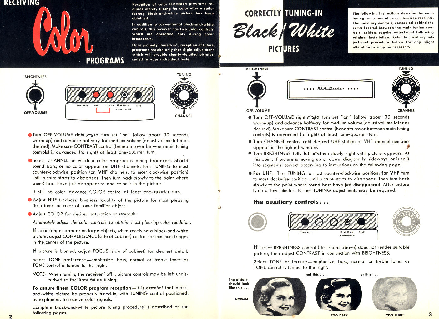
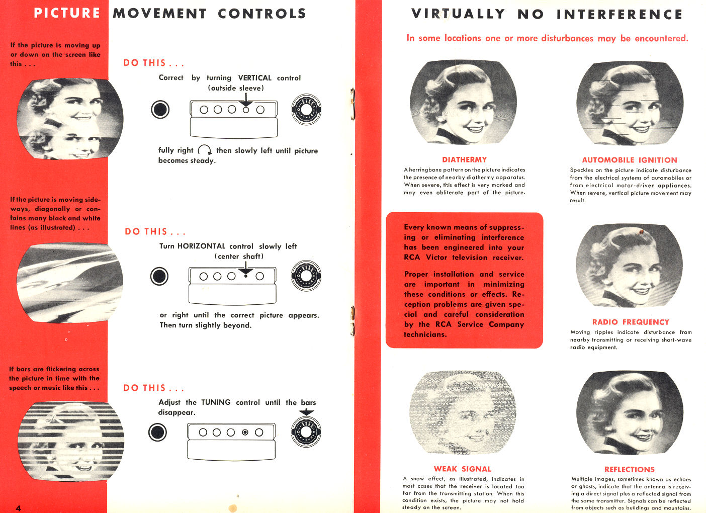
RCA CT-100 Owner Manual
Here is the front cover and operating instructions from the original
CT-100 Owner Manual. The rest of the slim booklet touts the TV's
features and gives warranty information.

RCA CT-100 Service Clinic Manual
This 54-page book was given to engineers and repairmen who attended one of the CT-100
service clinics that RCA conducted throughout the country. The manual contains three sections:
Principles of Color Television, Technical Features of the CT-100, and Installing and Servicing
the CT-100. It includes many illustrations in color and black and white, plus a full schematic.
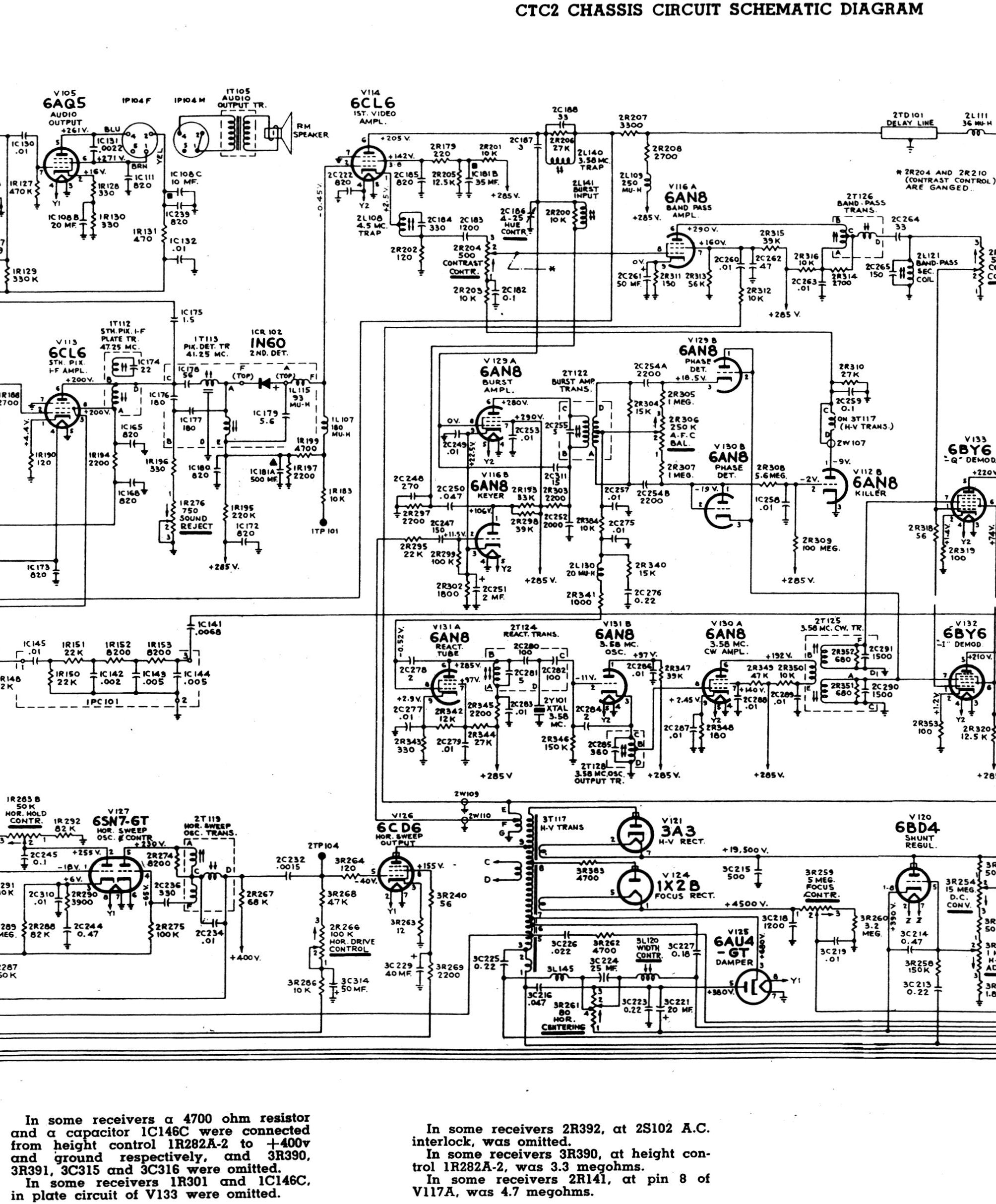
RCA CTC2 Service Manual T3
This 40-page RCA publication gives detailed service data and a nice technical description of
the CT-100. (Some of this information was replicated in the RCA Field Service Manual
listed below.)
RCA CT-100 Field Service Manual
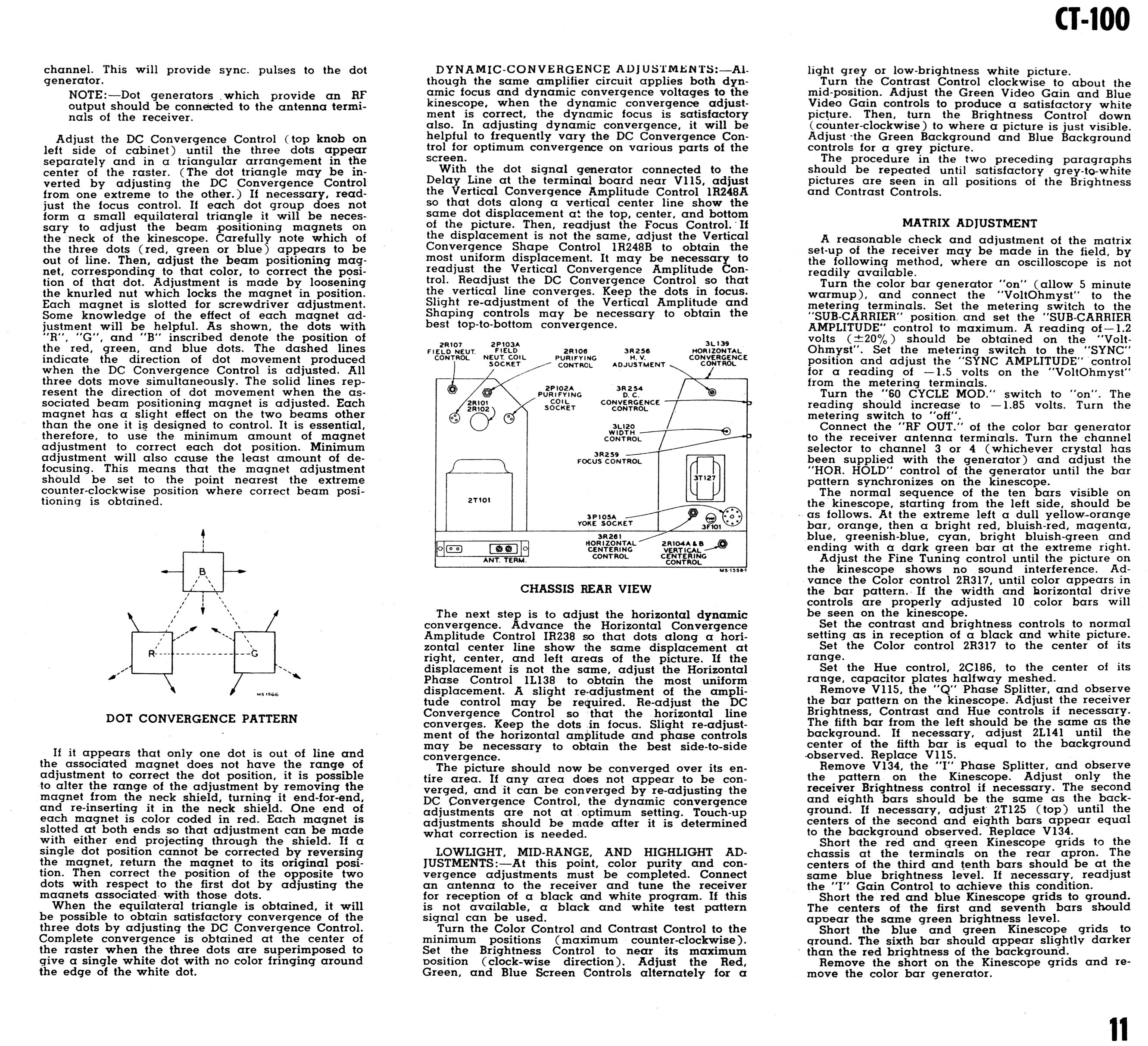
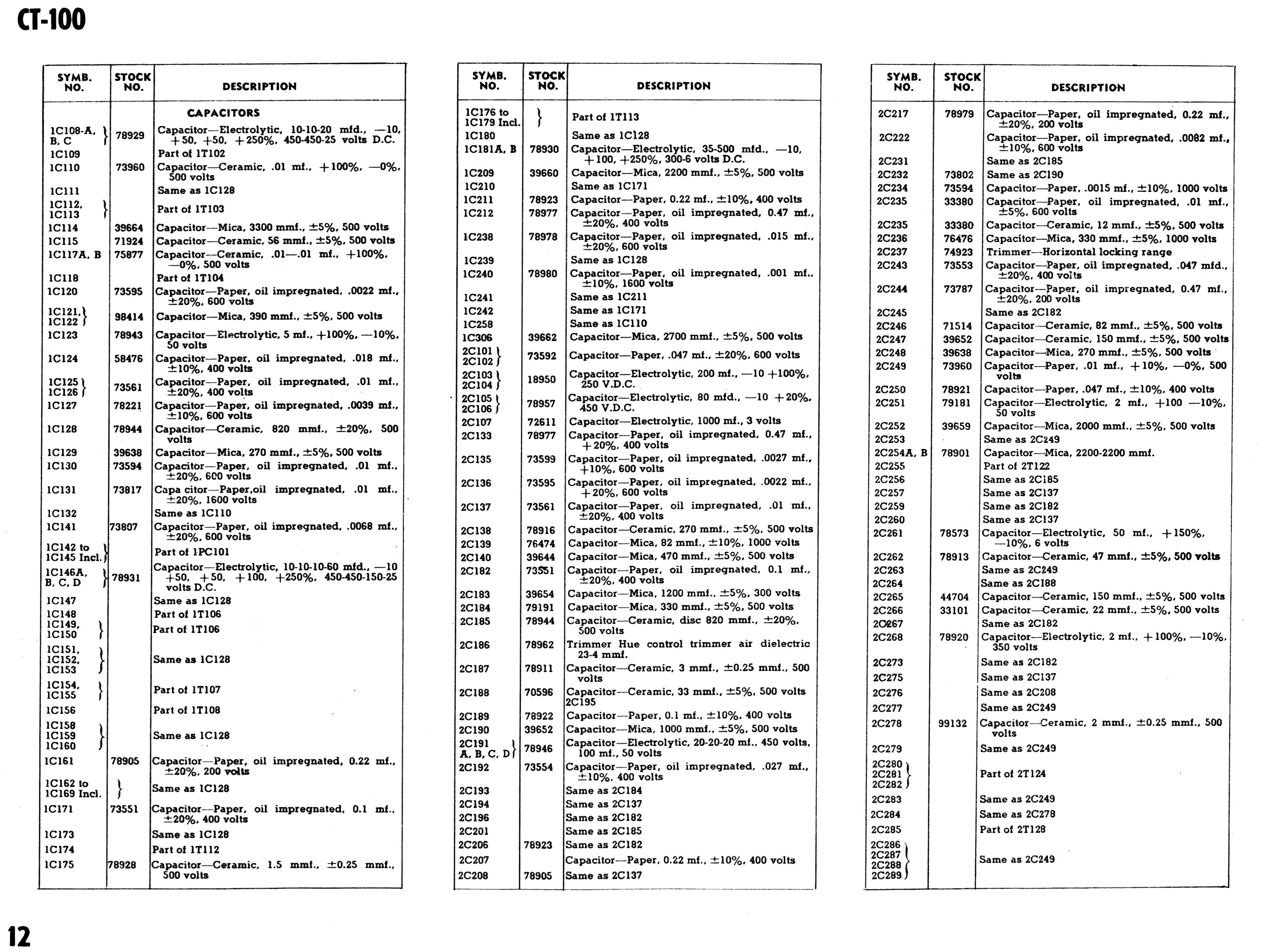
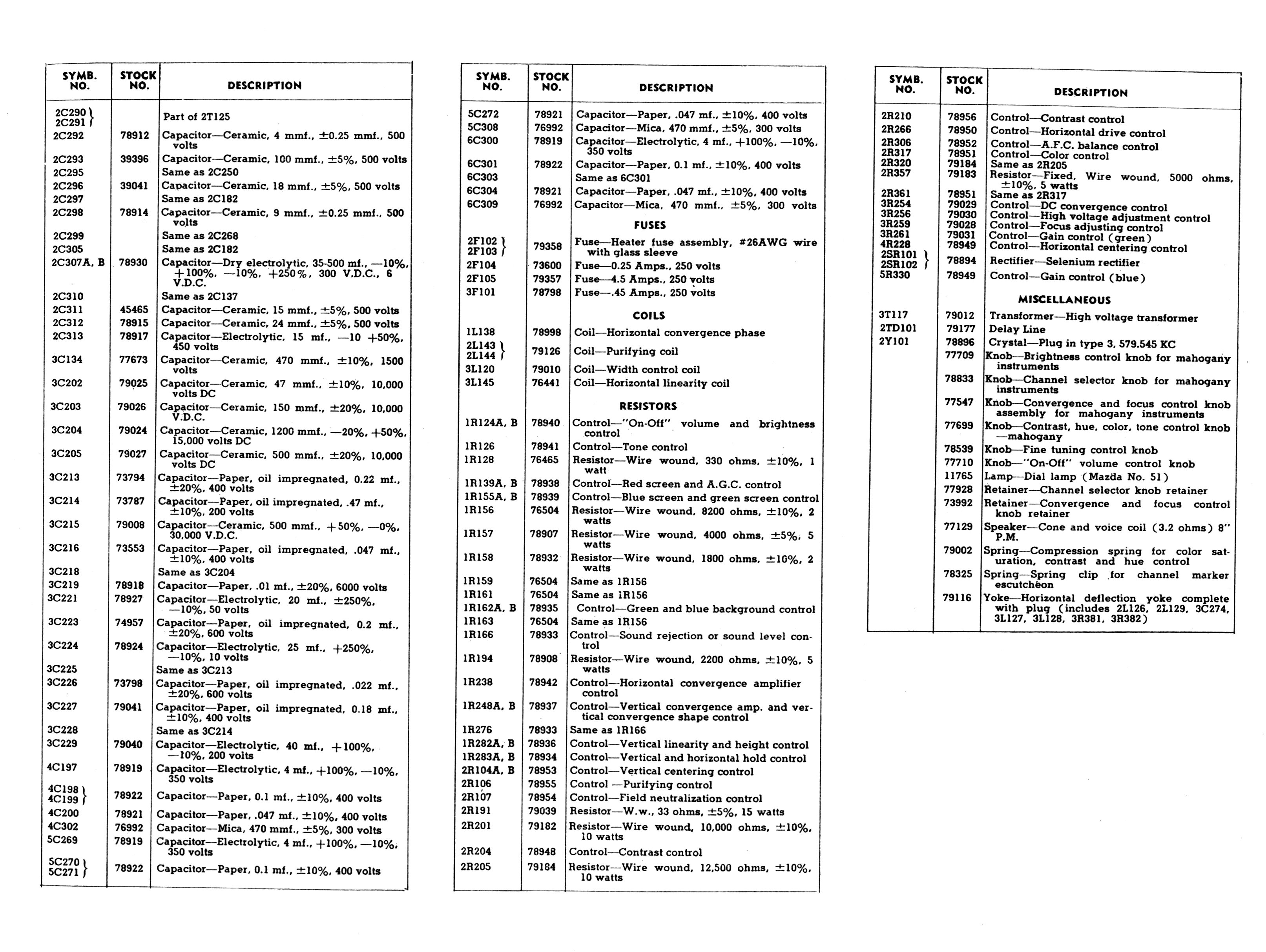
Below is the CT-100 section from the 1954 RCA Television Field Service Manual.
It includes a complete schematic, chassis layout diagram, installation
directions, setup procedures for convergence and the like, and a parts list.


I divided these long, skinny pages into sections that print on
8.5 x 11-inch sheets. Don't try to print them from your web browser. To save the files
on your computer for printing, right-click on each image and choose Save As...
A more detailed manual is the
CT-100 Sams Photofact,
Set 252, Folder 11. The Sams is a necessity if you're restoring a CT-100.
It includes detailed photographs identifying every component, voltage and
resistance charts, oscilloscope waveforms for various test points, and more.
There are at least three CT-100 schematics. The first, from the RCA field service
manual, appears here. Sams offers a second. A third was included
the Bernard Grob book below. The first and third schematics are similar
but not identical. As is often the case, the television underwent minor changes
during its production life, and some schematics have minor errors, so my advice
is to use all three.
"The CT-100 Commercial Color Television Receiver"
Next, we have "The CT-100 Commercial Color Television
Receiver," a 20-page article from the September, 1954 issue of RCA Review:
Written by two leaders of the CT-100 design team, this article gave the technical world
a first glimpse of this ground-breaking television. (This article included a schematic
diagram, but the detail of the original was poor. Please use the schematic from the
RCA Television Field Service Manual in the previous section.)
"Typical Color Television Receiver"
Here's a description of the CT-100 from Basic
Television, 2nd edition, by Bernard Grob, an instructor at the RCA Institutes.
Topping out at 660 pages, this textbook gives a complete survey of 1954 television technology.
The final chapter covers color TV theory and design, using the CT-100 as its teaching example.
Here is section 24-21, Typical Color Television Receiver:
This section also included a CT-100 schematic, referenced as Figure 24-37. Please
refer to the schematic included above in the RCA Television Field Service Manual.
Grob's book is a classic and I recommend it for anyone interested in 1950s television.
The 1954 edition is decades out of print, but it's available on the
used book market.
"The NTSC Color Television Standards"
This short, high-level overview of the NTSC color standard is aimed
at a non-technical audience. It's a nice summary of the main goals
and features of NTSC.
"NTSC Signal Specifications"
Here is the 1953 technical specification for NTSC color broadcasting.
The specification was promulgated as law via FCC regulation and
it is written with a curious blend of legalese and engineer-speak.
As in statutes, the word "shall" is mandatory,
meaning that any exception violates the rule.
The NTSC specification remains in force and all of the material in this document
currently appears in sections
73.681,
73.682,
and 73.699
of Title 47,
Code of Federal Regulations.
"A VHF-UHF Television Turret Tuner"
This article from RCA Review of September, 1953, gives an
extensive technical description of the tuner used in the RCA CT-100.
UHF broadcasting was not well developed in the mid-1950s and a
tuner that covered both VHF and UHF was somewhat unusual. Many
current and subsequent TVs used separate UHF tuners.
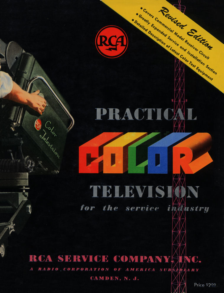
"Practical Color Television for the Service Industry"
RCA published this 80-page book in 1954 to explain color TV to experienced servicemen.
It covers many of the topics found in Bernard Grob's
Basic Television
but its style is concise and practical rather than academic. Like the Grob book,
it uses the CT-100 as an example of a "typical color receiver," including
a full schematic as well as block diagrams and theory. Its discussion of color
demodulation is one of the best that I've seen.
The book is available on the used market if you do a little looking. I don't have
space to reproduce all 80 pages, but here are a few illustrations to whet your appetite.


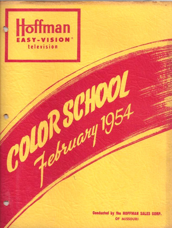
"Hoffman Color School, February 1954"
This 89-page course on color television was produced by the Hoffman company.
The 8-megabyte PDF document is hosted by the Early Television Foundation; click
here to download it:
Hoffman Color School.
The format suggests that this was a correspondence course, although it could also
have been used as the text for training classes. The content is very hands-on, aimed at servicemen
who were already familiar with black and white television. Here's the front cover; perhaps you'll run
across one in the dollar pile at a swap meet!
"Principles of Color Television, Hazeltine Laboratories"
This 595-page tome gives an exhaustive view of 1950s color TV technology.
If you're looking for a one-volume Bible for early color
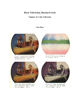
television, this it. Here's a famous color plate from its frontispiece.

This book was published by Wiley & Sons and is available on the used market.
Written in 1956, it describes the technology used to produce the RCA CT-100
and refinements in the two years since its production, such as
the use of larger 21-inch picture tubes. Here's the table of
contents:
- Light and Photometry
- Color Perception
- Color Space and Color Triangles
- Colorimetry
- Color in a Television System
- Required Information Content
- Characteristics of the Eye
- The Choice of Color Components and Their Interleaving in the Composite Signal
- Production of Composite Color Signal
- Synchronization
- Nonlinear Amplitude Relations and Gamma Correction
- The Color Standards of the FCC
- Decoders for Three-Gun Displays
- Decoders for One-Gun Picture Tubes
- Test and Measuring Methods
- Glossary of Color Television Terms
Hazeltine Labs was an interesting outfit. An independent research company, it
made money by inventing and patenting new technology, which it then licensed
to manufacturers such as RCA. An early success was the AGC (automatic gain
control) circuit that appeared, in one form or another, in most radios from 1930
onward and later in television. Hazeltine was deeply involved in early color TV development and
this book was coauthored by a dozen of its engineers.
Further Study
Another essential CT-100 resource is Pete Deksnis's
website.
His site is full of color photos and information about CT-100 restoration, written from about 2000-2009.
RCA was a prolific generator and collector of patents and there are many
which relate to early color television. For instance,
patent 2706217,
titled Color Television Control Apparatus, describes a system in which
"a carrier wave is modulated in phase and amplitude to represent the
color of a subject." Sound familiar?
Patents are easy to search and good for hours of fun if you don't mind turgid
prose. You can search for patents directly at the
US Patent Office website or the
Google patent archive
Note that patents are often indexed under the name of an individual inventor,
with the company (i.e., RCA) listed as the assignor. The name Alfred C. Schroeder
appears frequently in RCA patents of the time, either as the originator or as a reference.
I haven't tried to list other CT-100 Internet sources because they may change
at any time and you can find them as quickly as I can. Simply type terms like
"CT-100" or "early color television" into your favorite search
engine, and away you go!
If you come across other CT-100 resources that would be appropriate to list here,
send me an email.
|