National Model TV-7W Television (1948)


The National Model TV-7W is a charming, rather scarce 1948 television.
It's typical
of inexpensive TVs produced in the late 1940s and early 1950s.
National vs. Hallicrafters
National is best known as a maker of communications radios,
such as my little SW-54. In the immediate
postwar years, however, they dipped their toes into television,
perhaps as a hedge against the possibility that the
eagerly-anticipated TVs would make radios obsolete.
National's experiment with TV lasted only a couple of years.
The Hallicrafters company, another communications giant, also marketed televisions,
but with greater success. They stuck with television into the mid-1950s, eventually producing more than 50 different models.
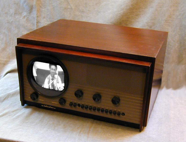
It's interesting to compare my TV-7W with my Hallicrafters
Model 505. Both were introduced in 1948. Both came in mahogany wooden cabinets with almost identical dimensions, and sold for a comparable price. They used the same picture tube and essentially the
same technology. Here are the two TVs side by side. The Hallicrafters set is
on the right.

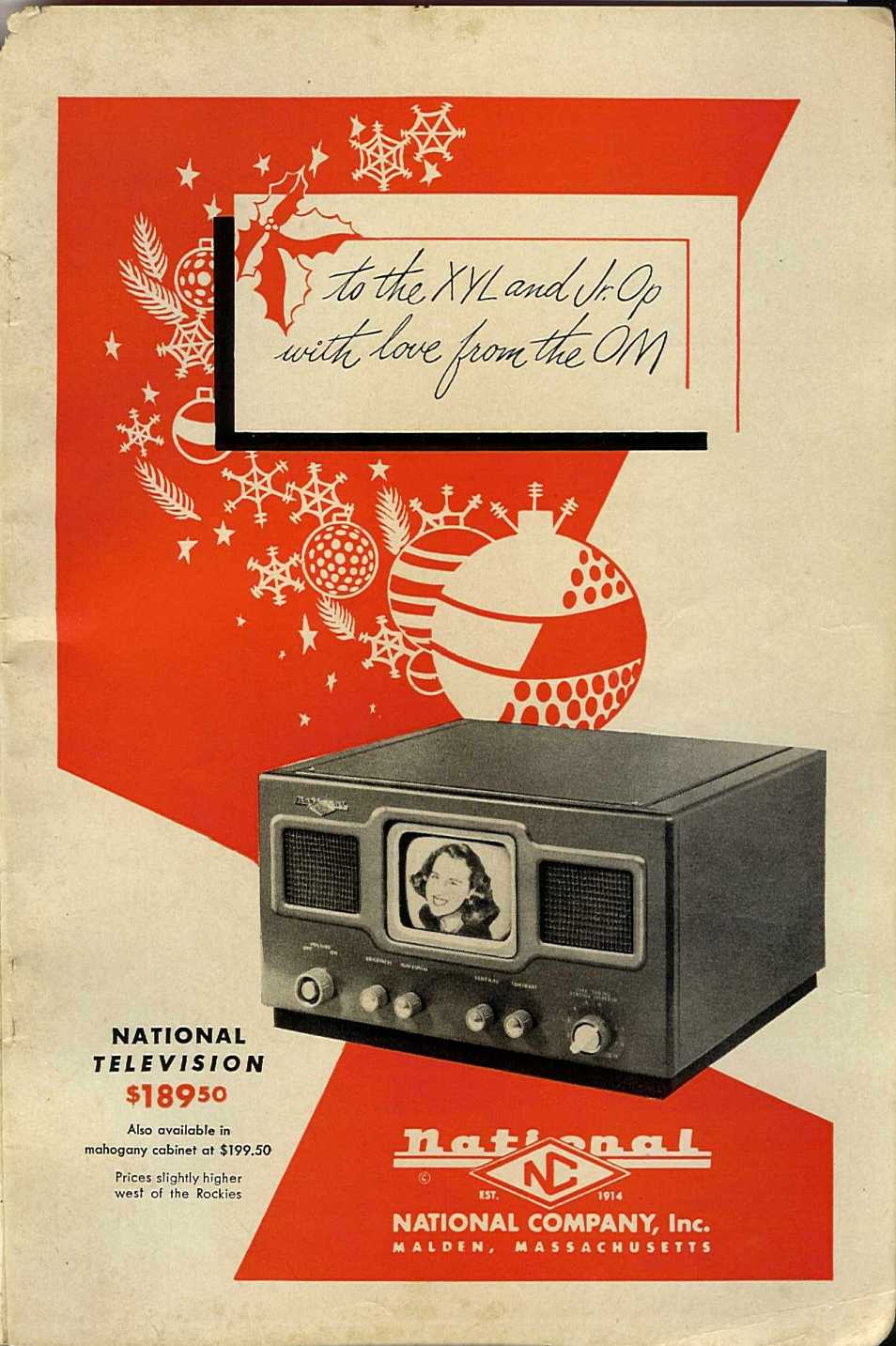
Both TVs were also offered in a grey metal cabinet, presumably to appeal
to the large customer base of communications radio enthusiasts. The
following ad shows the National TV-7M in metal. It was published
in QST Magazine, a leading ham radio publication.
Note the price: $189.50 for the metal cabinet, $199.50 for wood.
That was a fair amount of money in 1948, but still much cheaper
than TVs with larger picture tubes and console cabinets.
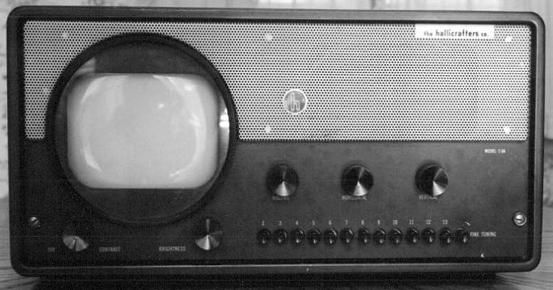
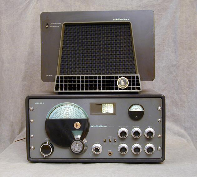
The Hallicrafters 505 was also available in a metal
"boatanchor" style cabinet. That TV, sold as model T-54,
is shown below. It purposely resembled Hallicrafters' extremely popular
SX-42 communications radio, shown to the right.
For both National and Hallicrafters, the metal-cased version was
far more popular than the wooden-cased one. No doubt the lower price
tipped the balance for many buyers, but promoting the metal version
to boatanchor lovers probably had an influence, as well. As far as
I know, these are the only TVs ever sold in a wooden "living
room" cabinet as well as a utilitarian metal one.
You can read more about the Hallicrafters TV in my
505 article; those sets are much
easier to find than the scarce TV-7.
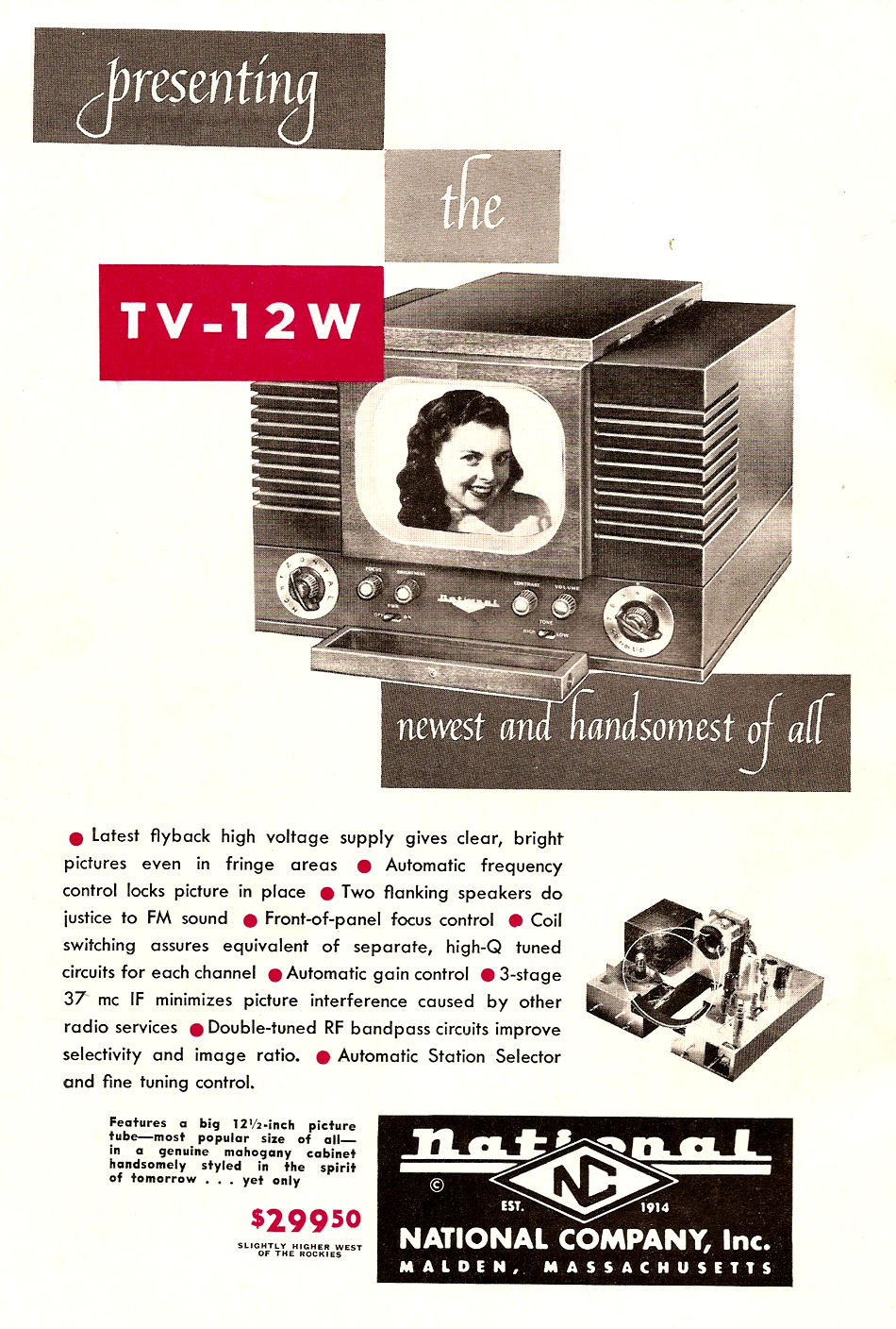
National produced two other televisions, the 10-inch model
TV-10T and the 12-inch model TV-12W. Apart from
screen size, those sets looked almost identical. Here's an ad for the TV-12W:
The larger Nationals are scarcer than the 7-inch models.
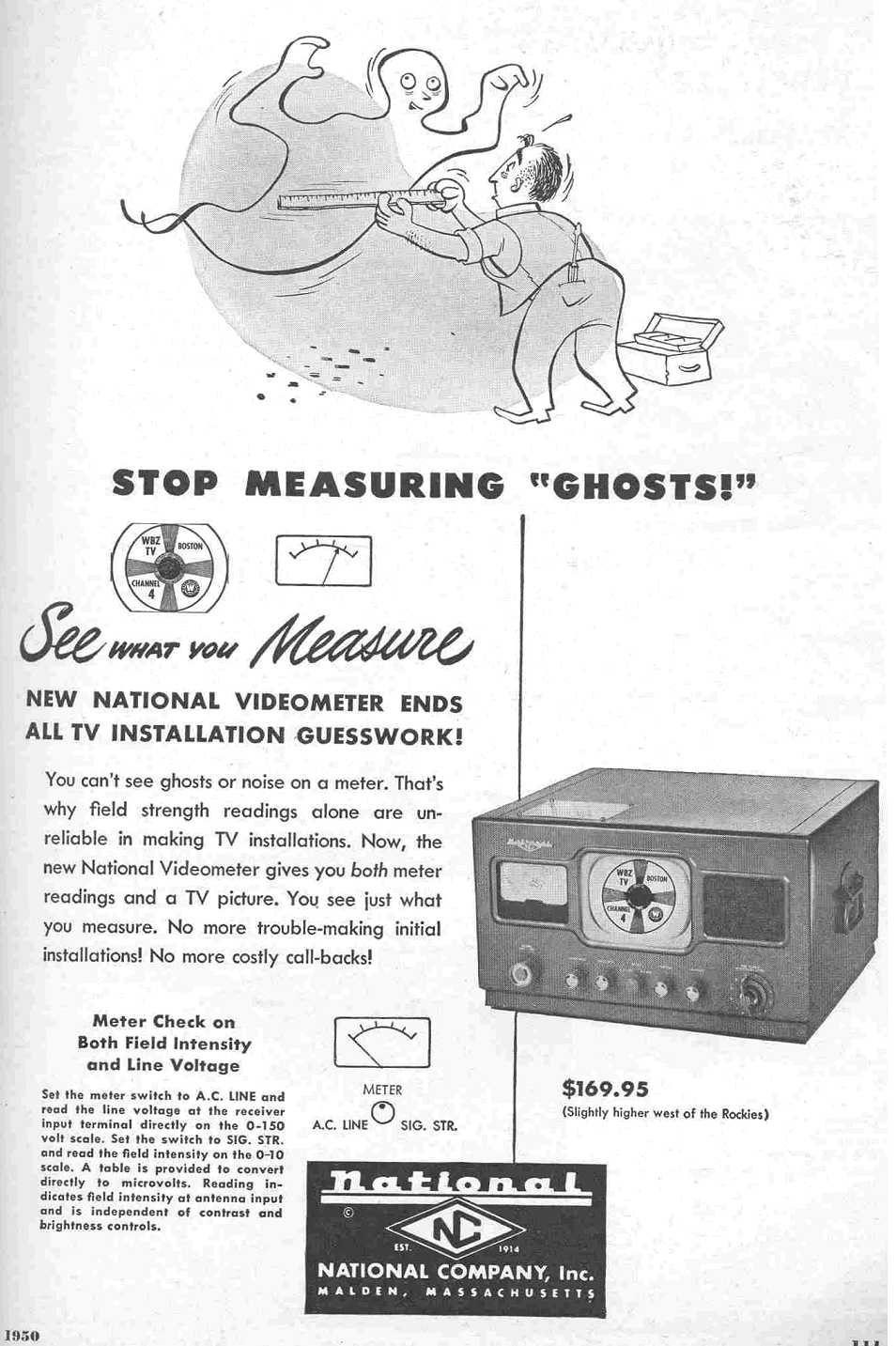
Another obscure National TV is the Videometer, shown in the
following advertisement.
Marketed to TV technicians, the Videometer is simply a TV-7 with
a TV field strength meter installed in place of one of the speakers.
It's sort of a clever idea, but the idea didn't take the world by
storm, probably because conventional field strength meters were
much cheaper and lighter than this bulky gizmo.
Description
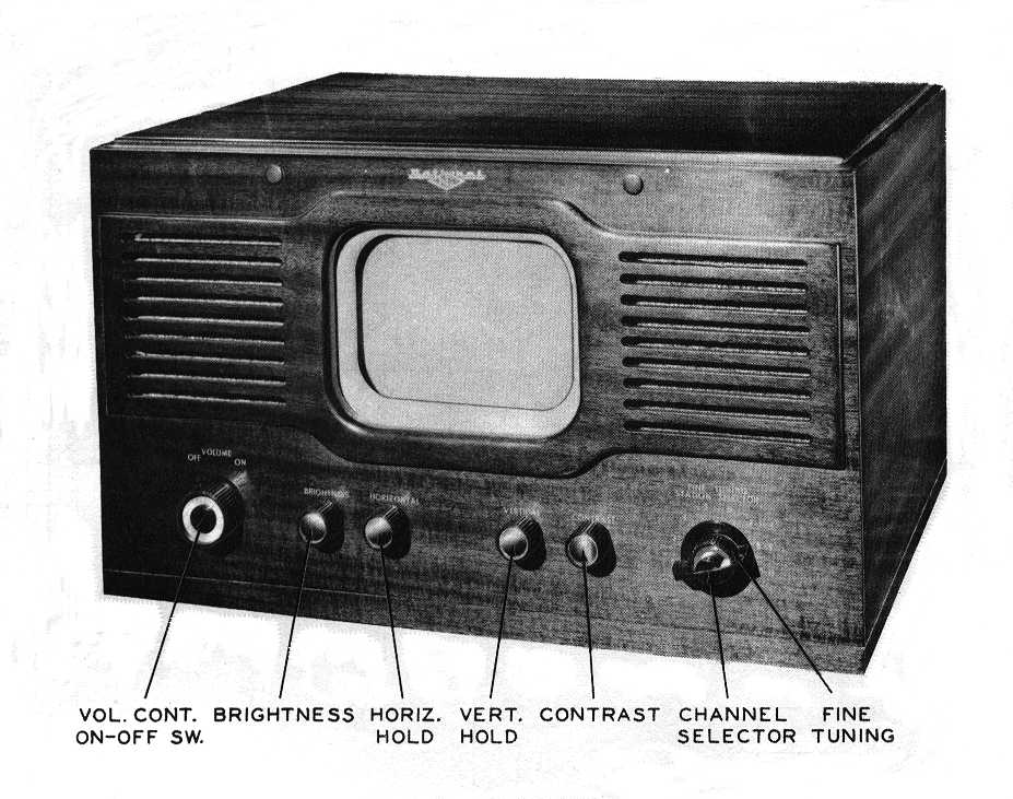
This factory photo shows the TV-7W's front controls:
Notice the two little wooden button plugs above the picture tube. These could be removed
to expose two holes, in which you could mount a magnifying lens in front of the
screen (a feature not supplied with my TV).
Small CRTs were the norm in the
early days of television. Tabletop sets like this used 7-inch tubes, which required
the viewer to be close to the set. Projection-type TVs, which had been made
from the late 1930s onward, used an even smaller 5-inch picture tube, whose image was
magnified through a lens and then reflected off a mirror toward the viewer. The Pilot
company sold a postwar tabletop TV (the TV-37) with a tiny 3-inch screen, the
smallest "direct view" television manufactured until Sinclair brought out
its 2-inch Microvision set 30 years later.
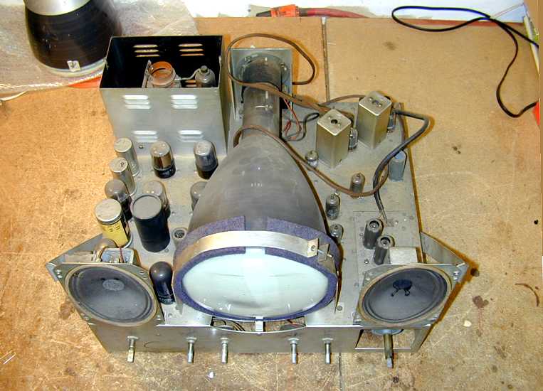
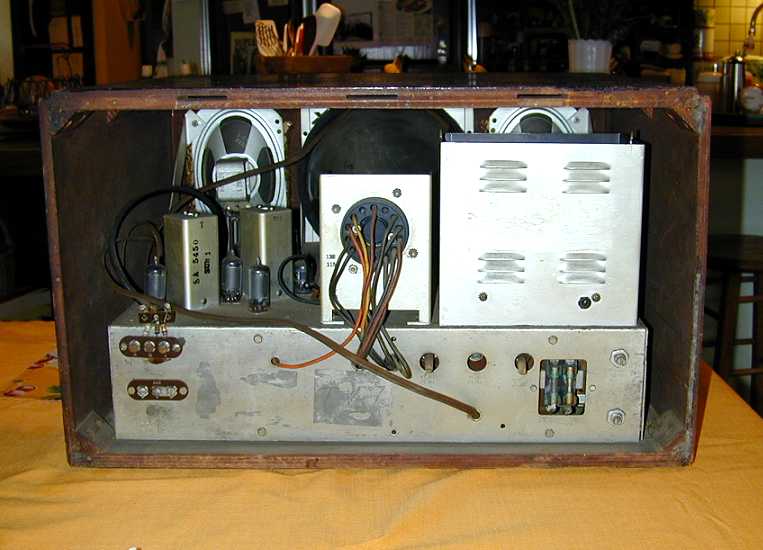
This photo of the restored chassis shows an unusual feature of the TV-7: dual speakers
mounted on each side of the centrally-mounted CRT. Dual speakers compensate somewhat
for the fact that there's no room for a big high-fidelity speaker in a
tabletop TV cabinet, although as any audio engineer will tell you, two inexpensive
4-inch speakers can't equal one high-quality 8-inch speaker.
The TV-7W uses 22 tubes, including a 7-inch electrostatic-deflection
type picture tube:
| Tube |
Type |
Function |
| V1 |
6AU6 |
RF amplifier |
| V2 |
6AG5 |
Mixer |
| V3 |
6C4 |
Oscillator |
| V4 |
6AU6 |
1st video IF amp |
| V5 |
6AU6 |
2nd video IF amp |
| V6 |
6AU6 |
3rd video IF amp |
| V7 |
6AL5 |
Video detector/AGC |
| V8 |
6AU6 |
Video amplifier |
| V9 |
6AU6 |
Sync clipper/DC restorer |
| V10 |
6AU6 |
Sound IF amplifier |
| V11 |
6T6 |
Ratio detector/AF amplifier |
| V12 |
6AT6 |
Audio amplifier |
| V13 |
6V6GT |
Audio output |
| V14 |
6SN7GT |
Vertical oscillator |
| V15 |
6SN7GT |
Vertical output |
| V16 |
6SN7GT |
Horizontal oscillator |
| V17 |
6SN7GT |
Horizontal output |
| V18 |
12AU7 |
High voltage oscillator |
| V19 |
1B3GT |
High voltage rectifier |
| V20 |
25Z6 |
Low voltage rect./Doubler |
| V21 |
6X5GT |
Voltage tripler |
| V22 |
7JP4 |
Picture tube |
If you compare this tube lineup to the Hallicrafters 505, you'll
see similarities in the number of tubes, their types, and their functions.
You can download the Riders
TV-7 schematic
from the Early Television Foundation.
There were two versions of the TV-7 chassis. The early version had a
power transformer and used a 5V4G rectifier tube. The later version
used a series-string power supply and a 25Z6 rectifier tube.
Mine is the later version with the tubes shown above. The earlier
version used 12-volt tubes in place of some 6-volt tubes (i.e.,
12SN7 instead of 6SN7) and had a few other differences, all
detailed in the Sams Photofact.
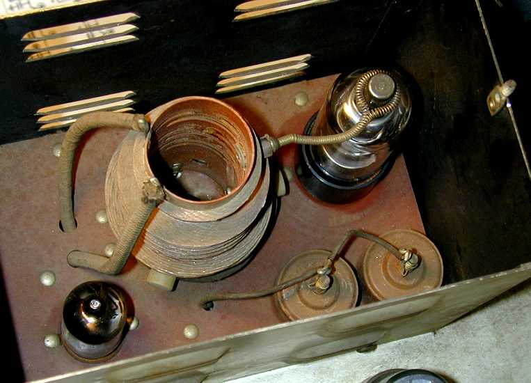
The following photo shows my TV-7 chassis at the time of purchase.

The chassis had the usual dust, but everything was there except for
the top cover of the high-voltage cage (upper left).
Note how the CRT
is held in place with a circle clamp padded with a generous
felt cushion. This contrasts with my other 7-inch sets, which rely
on simpler (i.e., cheaper) means of securing the CRT.
National's reputation for good
build quality can be observed in other components,
such as the expensive ceramic tube sockets and
switch wafers, and a gear-driven fine tuning mechanism. Along with
Hammarlund, another boatanchor manufacturer, National
was known for constructing its parts in-house
rather than buying off-the-shelf stuff from generic suppliers.
Given the date of manufacture, National might also have been using
up high-quality parts left over from wartime military production.
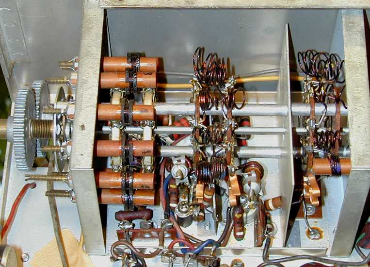
Here is a view of the gear-driven fine tuner.

Like my Motorola VT-73, this TV tunes in only eight channels rather than thirteen.
Since the FCC limited the number of broadcast stations in any city to eight, a
manufacturer could save a little money by simplifying the tuner. Each dealer
would set up the TV to receive the stations in that city.
In the previous photo, the brown tubes are the station tuning coils, which
the serviceman would adjust from the front of the chassis.
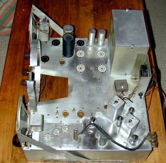
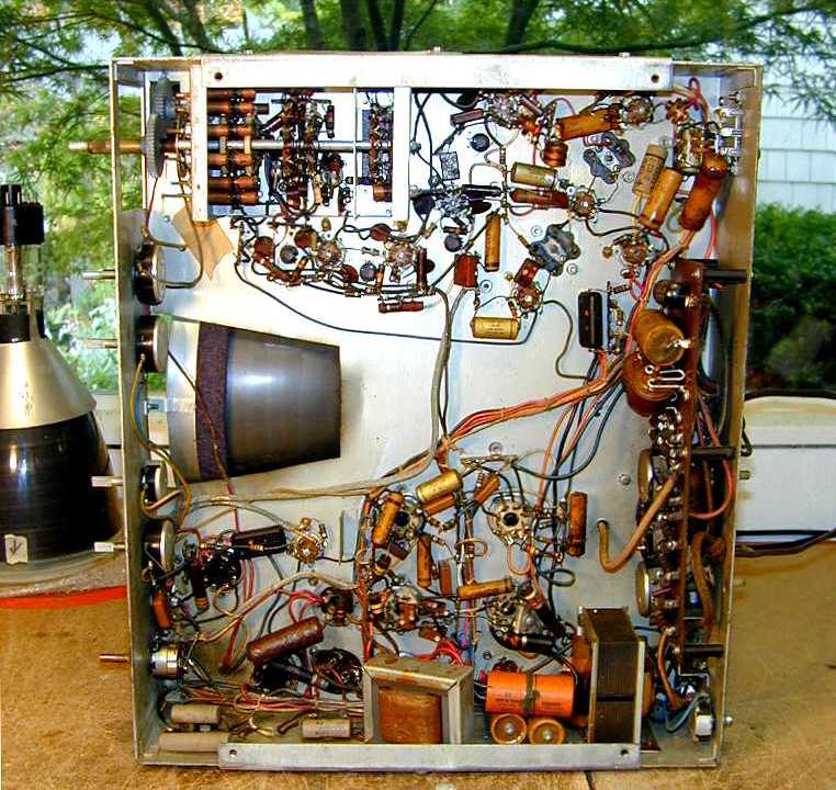
Here is the underside of the unrestored chassis.

This is an easy chassis to work on, with plenty of space
underneath. The rear chassis view reveals another welcome construction detail—two
fuses (lower right). Most TVs of this type and vintage had no fusing, an important safety protection that later became standard.

Below the antenna terminal is an unexpected three-element terminal labeled
AGC (automatic gain control), which brings the TV's AGC line out
for connection to something else. I'm not sure what purpose this
served.
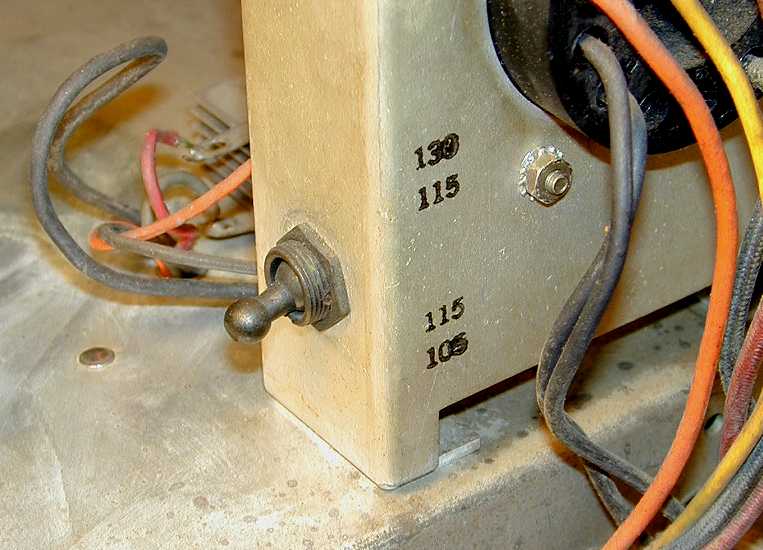
Yet another unusual twist is the line voltage switch. On the
side of the CRT mounting bracket is a toggle switch that lets you adjust
for higher or lower line voltage, in the range 105-115 VAC or
115-130 VAC.

In the 1940s, it was not uncommon
to have significant variations in AC line voltage from one area to
another, something almost unheard of nowadays.
Restoration
Much of the restoration work involved standard procedures such as cleaning the
controls with DeOxit, removing grime, and replacing
capacitors, so I won't repeat those routine measures.
Capacitors, Capacitors, Capacitors
This television uses some high-voltage capacitors which are worth
mentioning, however. And there are a couple of hidden
caps that you don't want to miss.
Like other 7-inch TVs, the TV-7 uses an electrostatic-deflection
picture tube which works differently than more modern electromagnetic-deflection
tubes.
An electrostatic-type tube uses four charged plates inside the
tube to deflect its scanning electron beams—two plates for horizontal
deflection and two for the vertical. An
electromagnetic-type tube, on the other hand, deflects the scanning beams with electromagnetic coils positioned
around the tube's neck.
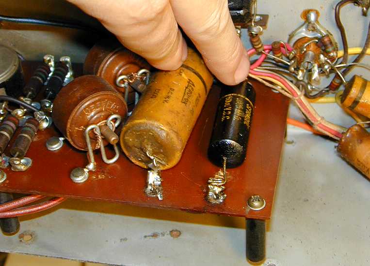
The capacitors used to transmit the deflection signals have a very high
voltage rating—10,000 volts in the TV-7. In the
Hallicrafters and Motorola TVs which I had previously restored, those
capacitors were very thick paper units. In the next photo, I am pointing
to two such capacitors.

Both capacitors had obviously been replaced at some point, one with a
thick paper unit of the original type, and the other with a slightly newer
(but equally unreliable) "Black Beauty" plastic-coated unit.
Notice the chubby, millwheel-shaped capacitors toward the left
in the previous photo. This is a type of mica capacitor, very reliable and often called
a "doorknob." Here's a snippet of a Sprague
capacitor ad featuring such capacitors rated as high as 20,000 and 30,000
volts.

Peering inside the high-voltage cage, I found another pair of doorknobs.

This type of capacitor is often used as a filter in high-voltage circuits.
I left all of the original doorknobs in place.
After replacing the remaining two high-voltage CRT coupling capacitors
and all of the nine (!) electrolytics, I cautiously powered up the TV
and was rewarded with my first intelligible picture.
The TV-7 has a couple of hidden capacitors that you don't want to overlook.
One of them is underneath the bottom plate of the high-voltage cage, as
shown below.

You will need to unsolder the cloth-covered high-voltage lead from underneath the chassis
to get enough slack to turn the cage on its side. While you're inside the
cage, check the values of the resistors and mica capacitors and replace them if
their values have changed.
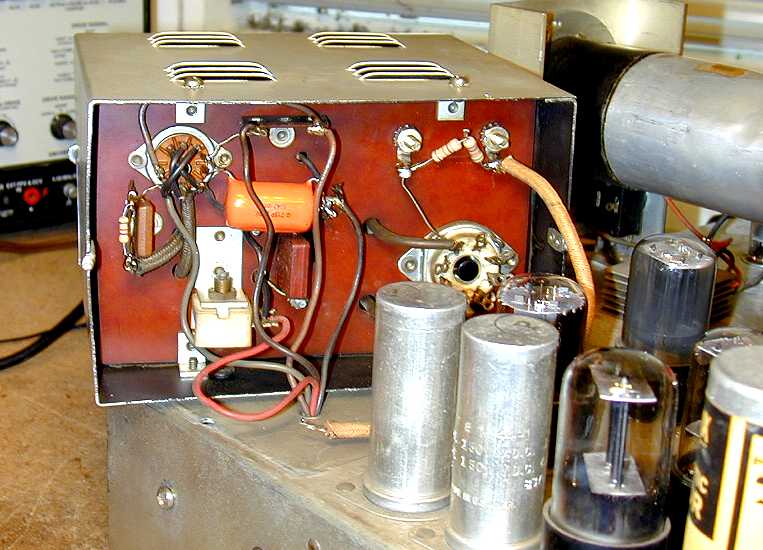
Another capacitor is hidden under the phenolic board at the back of
the chassis that carries
high-voltage components such as the doorknob caps.

You should be able to reach that cap by loosening the insulated standoffs
and lifting the board away from the chassis a bit. This photo, and the
previous one, were obviously taken after I had replaced the original
paper capacitors with new "orange drops."
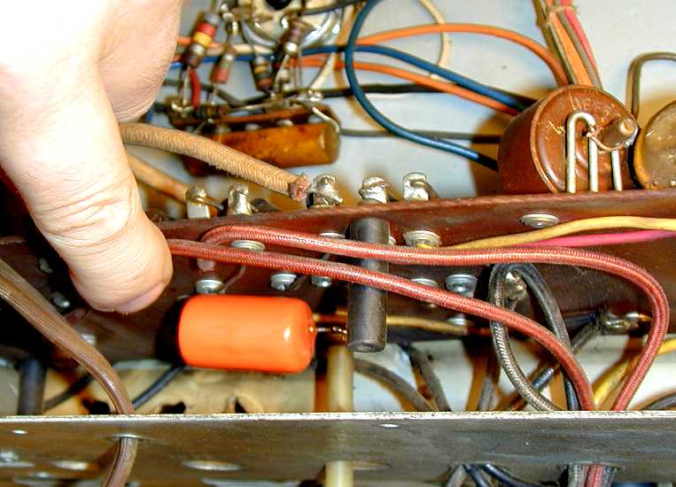
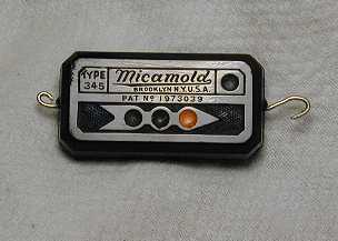
One last gotcha to mention before we leave the fascinating topic of
capacitors. Near the HV board you will find a "micamold" type paper
capacitor that looks like this.

Although it somewhat resembles a (usually reliable) mica capacitor, this is
an unreliable paper capacitor in a plastic case and it should be replaced. See our
replacing capacitors article for more details
on hunting down these bad boys.
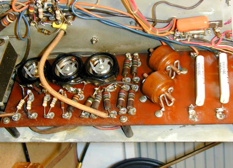
High-voltage Resistors and Potentiometers
In all tube TVs, it's a good idea to check all high-value resistors
(1 megohm and higher) and replace any whose value has drifted more
than 20% above the original specifications.
Like similar 7-inch TVs, the National uses several resistors, ranging
from 1 megohm to 4.7 megohms, in the high-voltage circuits which
feed the picture tube. A cluster of them is mounted on the
HV board mentioned earlier.

Four of those resistors had already been replaced at this stage of the
project, as you can see. Also visible is the "underneath" end of
the high-voltage lead that needs to be unsoldered to replace a capacitor
under the HV cage, as mentioned previously.
This photo also shows two new high-voltage
capacitors (the flat white ones to the right) and three high-voltage
potentiometers (whose case backs have been removed).
These three potentiometers are for adjusting the TV's focus, vertical centering,
and horizontal centering. All are rated at from zero to 5 megohms resistance
and they are critical for proper operation.
Because they are in the high voltage circuits, these potentiometers are mounted
on the HV board, insulated from the chassis, and they also have plastic rather
than metal shafts, to protect against shock.
This type of pot is constructed differently than the cheaper ones you'll see in
lower-voltage applications. Cheaper pots work by sliding a contact around a resistive
carbon layer. These work by sliding an insulated pad around a springy inner collar,
which contacts a resistive layer around the perimeter.
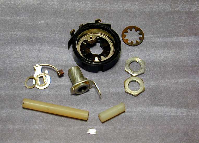
All of these pots were still functional on my TV, but one of them had a cracked
shaft. When I carefully brushed dust away from the back of the chassis with a paintbrush,
the shaft finally snapped off!
Fortunately, this type of potentiometer can be completely disassembled and is not hard to
repair. The following photo shows the pieces, complete with the snapped plastic shaft and
a small metal "key" that I fabricated to repair it.

If you take one of these apart, note the order of the pieces, so you can replace
them correctly.
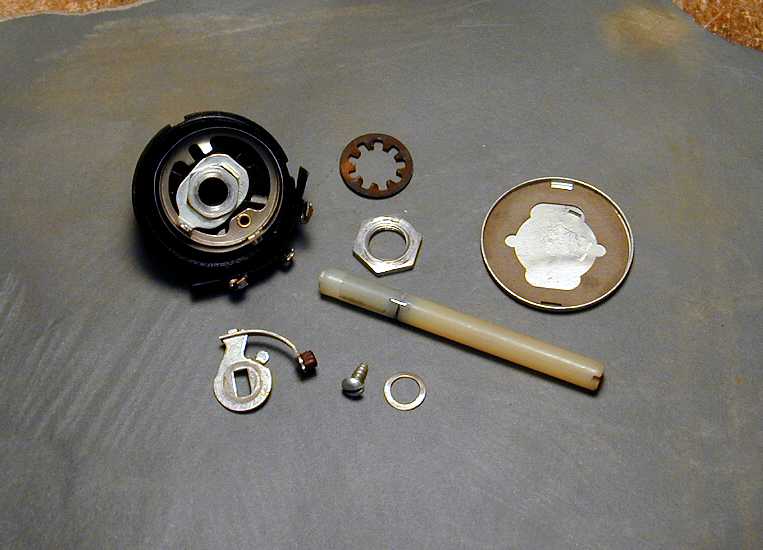
To repair the shaft, I first snipped a tiny piece of sheet metal (cut from a soup can) to
the same diameter as the shaft. Then I cut a slot in the snapped end of each shaft, where
I could insert the metal key to reinforce the joint.
The next photo shows the repaired shaft, ready to put back into the potentiometer. I glued
the key into the two pieces of the shaft using JB Weld Epoxy, then carefully sanded the
edges of the repair so that the shaft would turn smoothly inside its collar.

Tweaking Horizontal Problems
At this stage, I had a reasonably good picture. A few more tweaks were needed,
however. Once again, I called on the rec.antiques.radio+phono newsgroup for
advice.
From: "Phil Nelson"
Subject: horizontal problem (or not?) in National TV-7W television

After much work, I have a good picture on my National TV-7W television.
If I turn up the brightness enough to show some retrace lines, however,
a faint vertical bar appears at the left of the screen.

It's almost as if the scan flies a little "too far left" before getting
back in sync. If I reduce the brightness to make the retrace lines
disappear, this problem disappears. Horizontal and vertical lock are
very stable.

Here is the schematic for the TV's horizontal section.

The vertical bar doesn't appear to contain any data. This looks more like a
retrace issue.

A little while ago, I adjusted the drive trimmer cap on pin 4 of the
horizontal output tube to correct a horizontal linearity problem
that caused the picture to be too squished and bright on the right side.
The 4.7 meg resistor on pin 4 has been replaced, but the two 47K
resistors have not been replaced. The trimmer is turned as far as it
can go at this point. Should I mess with other components on the output
tube until I can get a little more adjustment out of it? Or is that
barking up the wrong tree?

The actual picture looks considerably better than this blurry off-air
snapshot. If I turn down the brightness a bit, this problem is masked, but
it's distracting when changing channels. The ideal brightness/contrast/fine
tune adjustment for one channel won't necessarily give the best picture on
another station. Which brings up other questions involving AGC and
alignment, but . . .

-----------
From: "Brenda Ann"

That's the horizontal blanking interval... it's the same as the vertical
blanking interval, but at horizontal frequency (the bar you see when the
picture 'rolls').  Normally, I have seen this bar on the right side of the
screen, but depending upon the peculiarities of your horizontal sync
circuit it could sit on the left as well. It's not a big deal, but you can
try adjusting your horizontal hold to see if the bar disappears.

-----------
From: Robert Casey

Looks like a phase error.  That is, the phase of the horizontal oscillator's
output is off in terms of time compared to the video signal. Looks like the
oscillator is a few microseconds too early in commanding a retrace.  There
usually are RC circuits to separate the horizontal sync from the vertical
sync, and if one or more parts in those RC circuits are way off, could
cause phase errors.

Or a bad resistor in the oscillator could do it.  I assume you replaced all
the wax caps. Don't use ceramic caps though, temperature drift can mess
up horizontal oscillators.

It's also possible that the designers expected you to overscan the image
more.  C78, R33, R10 and R35 may be making a variable phase shifter as
well as horiz size. Adjusting R10 for more overscan might remove the phase
error.  Of course the horizontal sync bar will disappear, but be sure the
TV image center is centered.
Armed with these clues, it wasn't hard to solve the problem. Replacing a couple
of marginal resistors and a mica capacitor in the horizontal circuits did the trick.
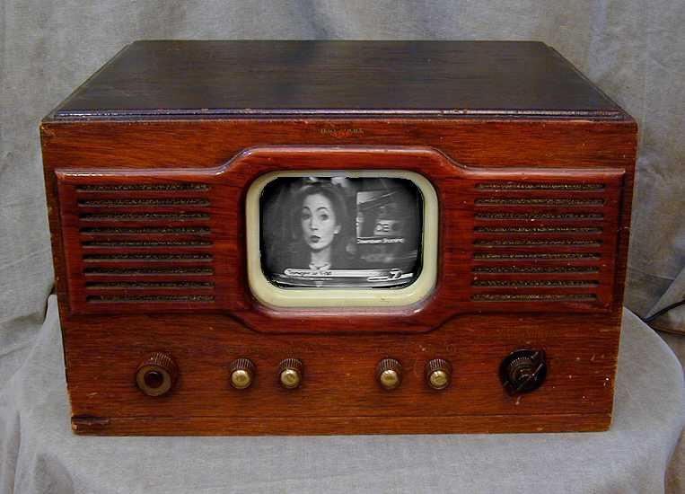
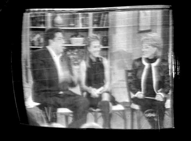
Here is the TV picture as it appears today, about two years after I finished the restoration.
The television was receiving a local newscast, using a rabbit ear antenna.
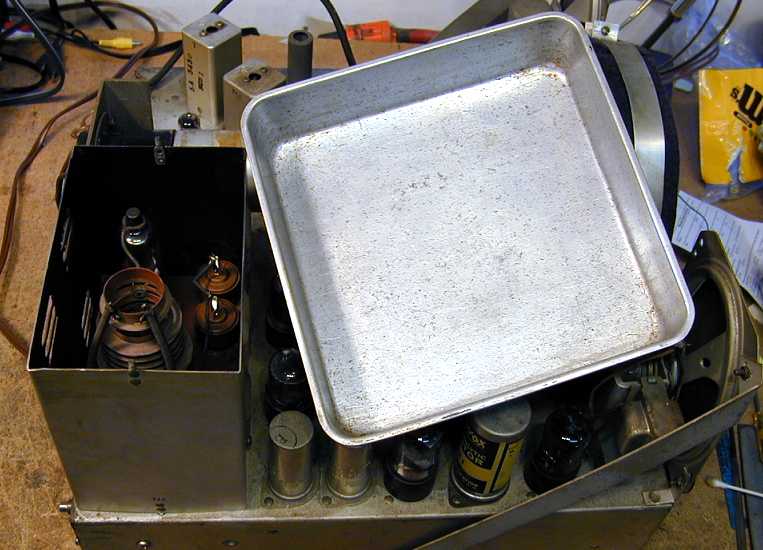
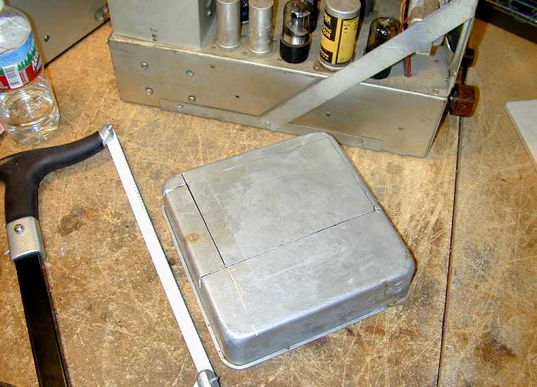
Cake Pans to the Rescue!
One last job remained before I could call this project complete. As noted earlier, this TV
was missing the little cover for the top of its high-voltage cage (which contains the
HV picture tube coil and 1B3GT HV rectifier). The following photos show how I fashioned
a replacement from an aluminum cake pan, which I got for 50 cents at a local thrift store.


The third photo shows the new cover plate (upper right) atop the high-voltage
cage, on a newly-cleaned chassis. The TV-7 chassis is made of aluminum which
shines up nicely with any sort of metal polish.
Final Thoughts
This was a satisfying project, somewhat easier than restoring my other 7-inch TVs.
Some of the ease comes from experience. When restoring the third television of a
particular type, you know what to look out for.
Quality is another factor. This national TV uses higher quality components than
its contemporaries, for the most part.
Chance occasionally plays a role, too. My Hallicrafters 505 had been cannibalized
for a few spare parts, for instance—the sort of thing one would never anticipate.
This television's cabinet still needs restoration. Mahogany is a beautiful wood, but
rather soft, so this cabinet has considerable weathering and quite a few scratches,
especially on the top. The good news is that these defects are easily remedied.
The decals will need to be replaced after refinishing, of course. It's easy to find
decals for generic figures such as the channel numbers and words such as Horizontal.
To replace the National logo, however, I'll need to supply a digital image of the original.
The height of the logo on this TV is about half the width of my little fingernail.
I took a digital photo of the decal. Then I resized the image and started cleaning it up
for reproduction. It's a painstaking, fussy process, which I haven't quite finished to
my satisfaction. The good news is that you don't need
to supply an image with exactly the colors that you want.

For the above image, for instance, all I need to tell the reproducer is that "yellow equals
gold," "black equals clear," and "red equals maroon." They can
substitute appropriate colors when
they make the decal (for a fee, of course).
I'll update this page after I finish the cabinet restoration.
The National TV-7W is a cut above the average 7-inch television.
If you only have room for one of these in the house, it would
be an excellent choice. I restored mine several years ago and
it is a stable, reliable performer.
|

