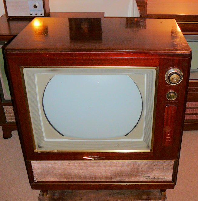
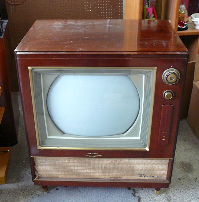
RCA Model CTC-4 "Director 21" Color Television (1955)


Produced one year after RCA's pathbreaking
Model CT-100, the CTC-4 color television
shares many of the CT-100's attributes and adds a larger 21-inch picture tube.
Marketing the CTC-4
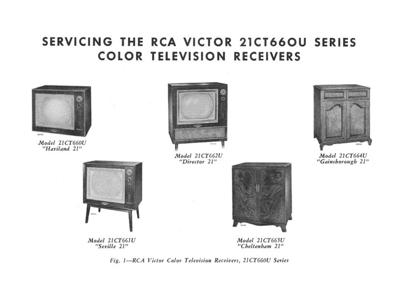
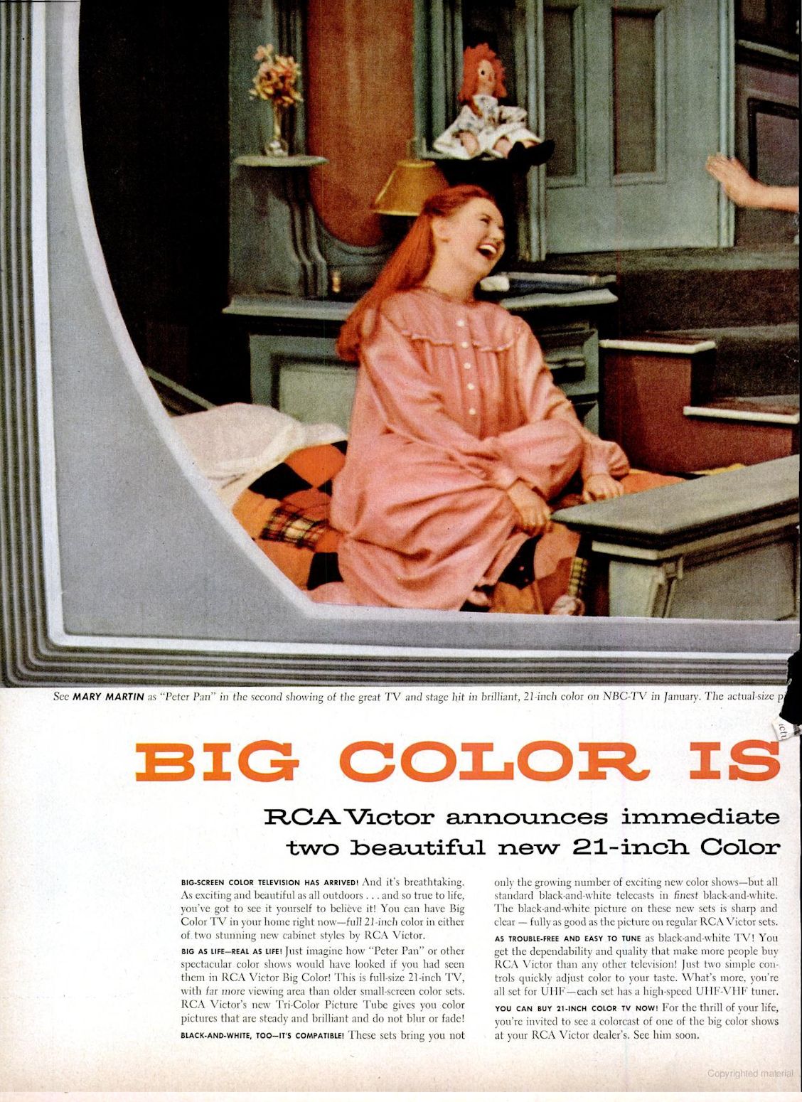
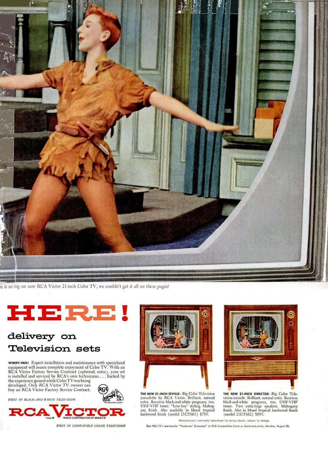
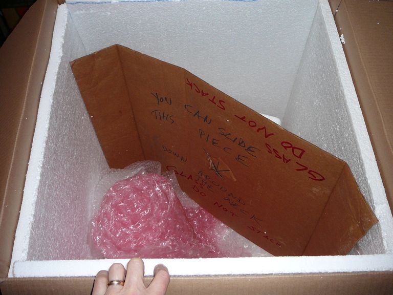
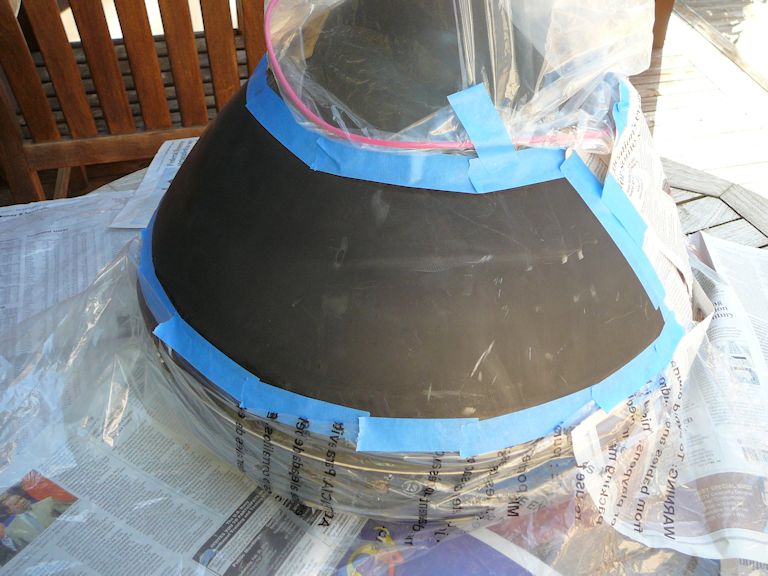
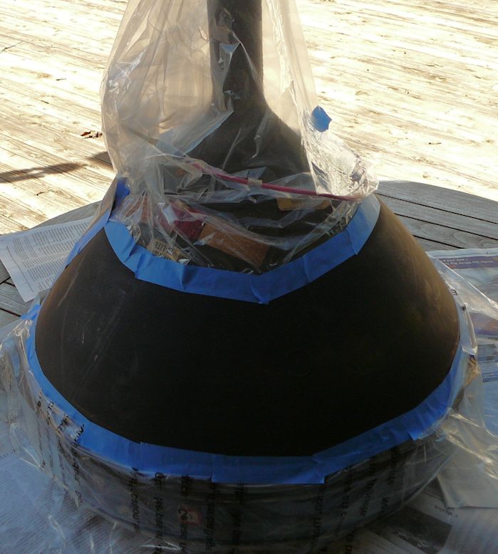
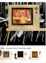
RCA offered the CTC-4 television in five cabinets, named Haviland, Seville,
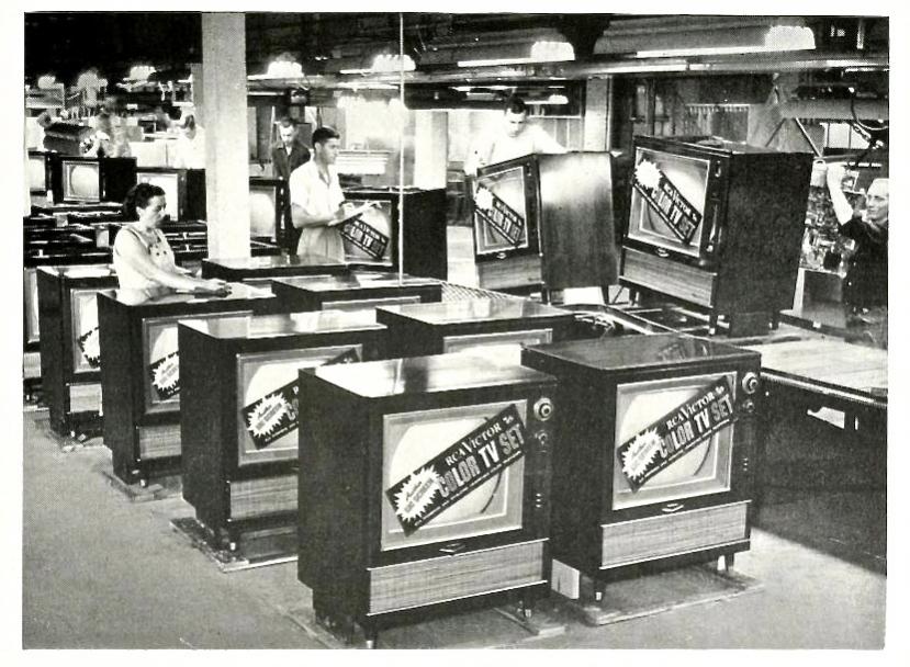
Director, Cheltenham, and Gainsborough. My set is a Director. The second photo, provided
by Steve Dichter, shows Directors coming off the assembly line.


Priced at $895, the Director anchored the middle of RCA's color TV line for 1955. Least expensive
was the Haviland, with a metal tabletop cabinet and a single speaker. The Seville was a Haviland
with a wooden cabinet and optional stand. The Director had a
wooden console cabinet and two eight-inch speakers. The top-end Cheltenham and
Gainsborough consoles had three speakers and fancy cabinets with doors.
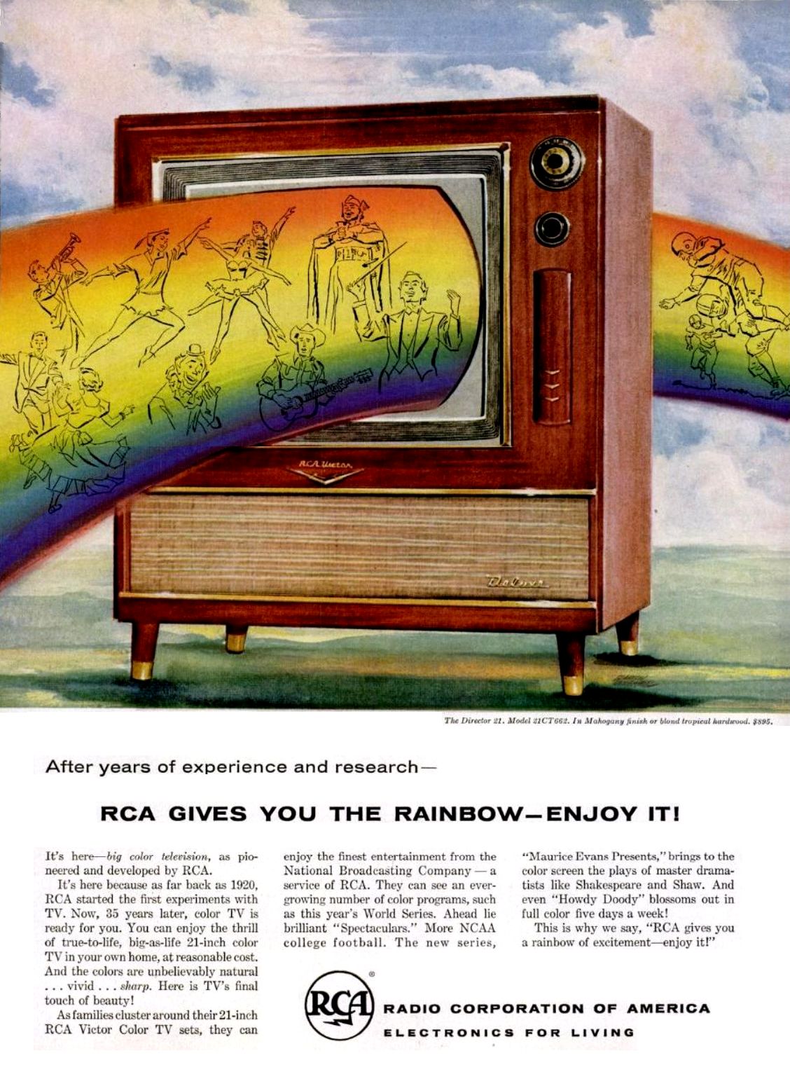
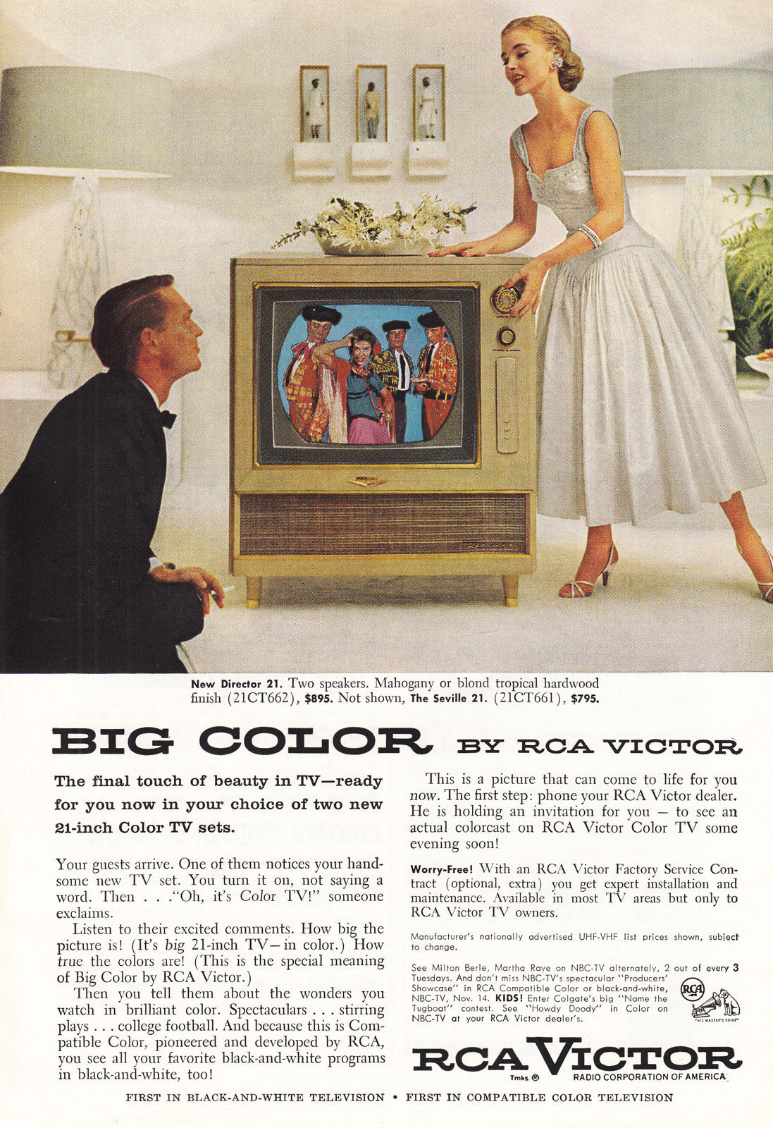
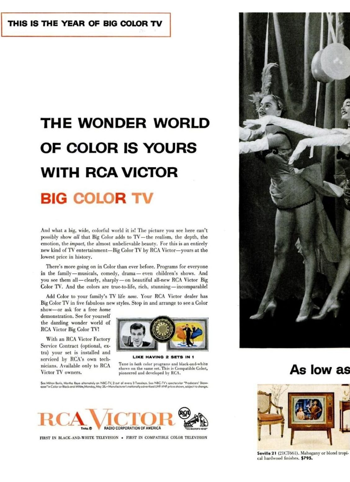
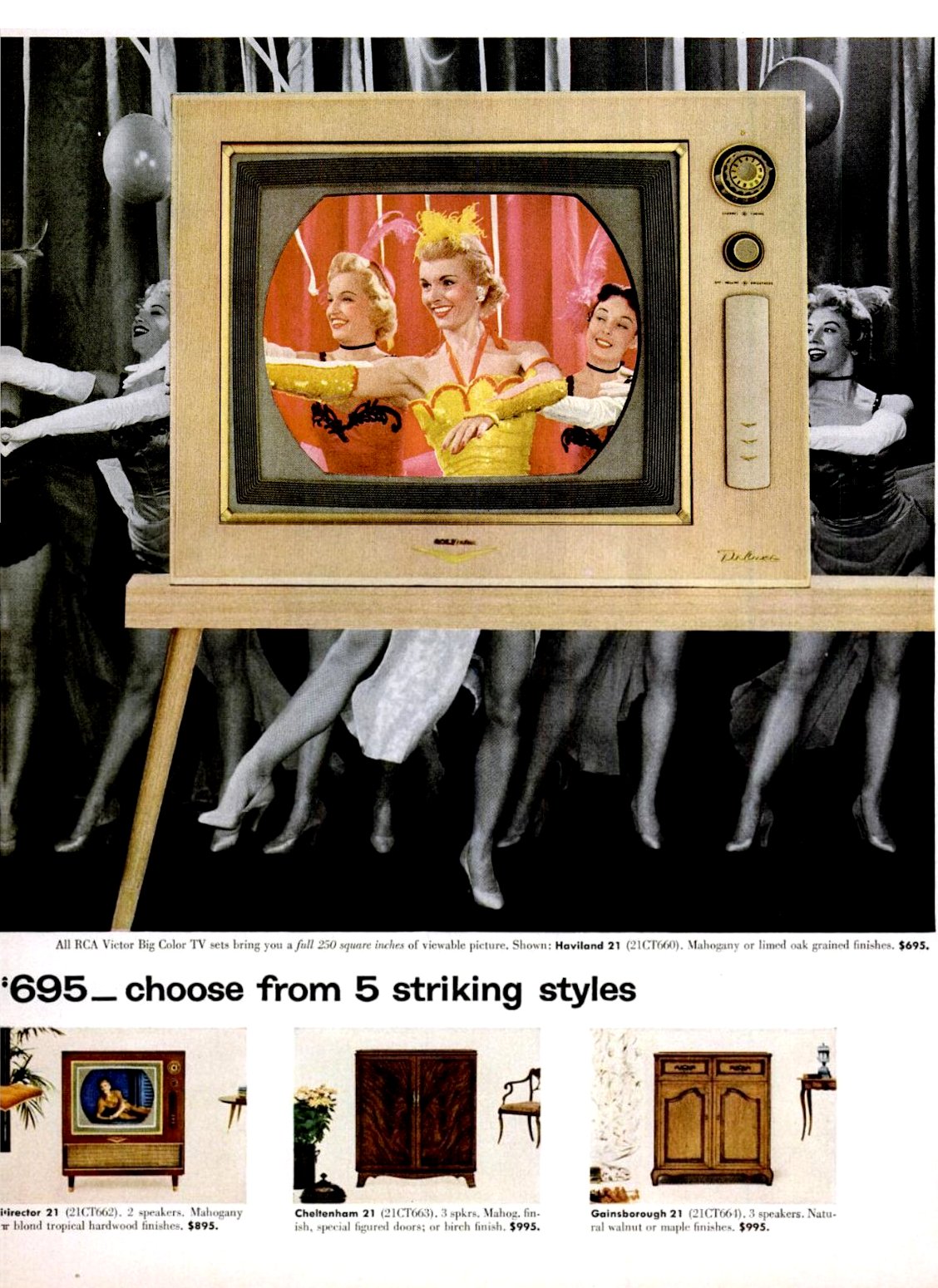
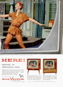
RCA promoted the CTC-4 as its finest television and spent lavishly on advertising.
These ads ran in 1955 and 1956:


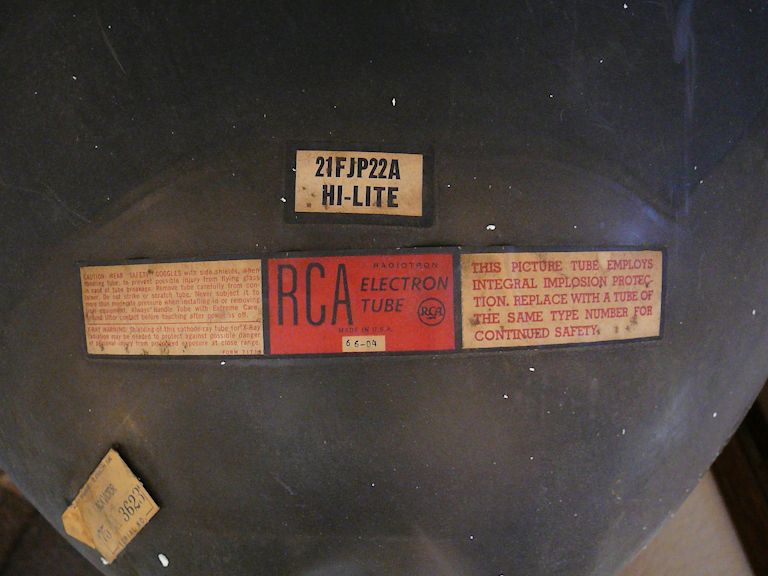
RCA's model numbers indicate which cabinet the TV has. My "Director 21"
is a model 21-CT-662U. The same TV in a "Seville 21" cabinet is model
21-CT-661U, and so on. Collectors call these TVs CTC-4s because
they share the same chassis. The chassis number is shown in a black
rubber stamp on the rear of the chassis. The model number appears on the back
cover, as we'll see below.
Technical Description
Like the CT-100, the CTC-4 can receive UHF as well as the standard VHF channels,
a rather uncommon feature in 1955, when UHF stations were not widespread.
The CTC-4 marks an interesting stage in color television development. As explained in my article on
CT-100 electronic design, one can use different
methods to demodulate (decode) the color information in a TV broadcast signal, and these
methods affect the quality of the color picture. The CT-100 used what is called I-Q
demodulation, a complex method that renders colors very accurately.
The CTC-4 used a unique method known as R-Y/G-Y demodulation. Later TVs
used the R-Y/B-Y method, or, like my
CTC-7 and
CTC-11, a fourth method known as
Z and X demodulation.
Those TVs used different picture tubes that had different phosphor blends, so
it's impractical to make a direct apples-with-apples comparison to show the difference
in their demodulation methods. Each of them will make a satisfying and realistic color
picture, but experts might notice certain differences.
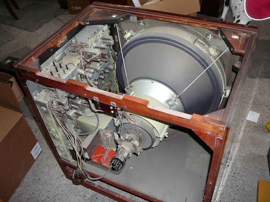
Whereas the CT-100's chassis lies on the bottom of its cabinet, the CTC-4 chassis is mounted
on the side. This moved the controls up and made them easier to reach, and this change was
carried forward in later RCA color TVs like my CTC-7 and CTC-11.
As in the CT-100, rarely-used controls such as Hue are hidden behind a "pencil box" cover.
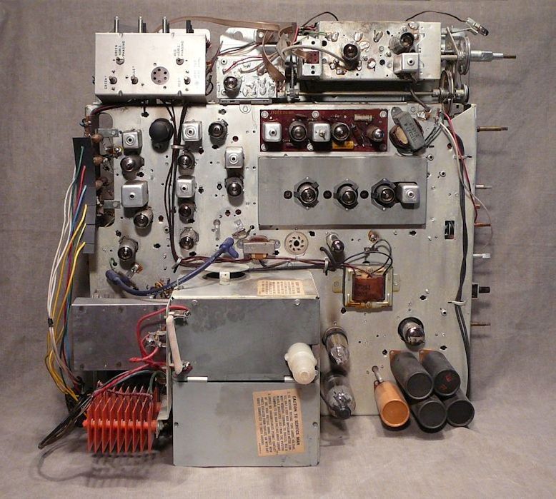
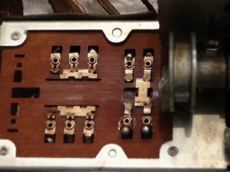
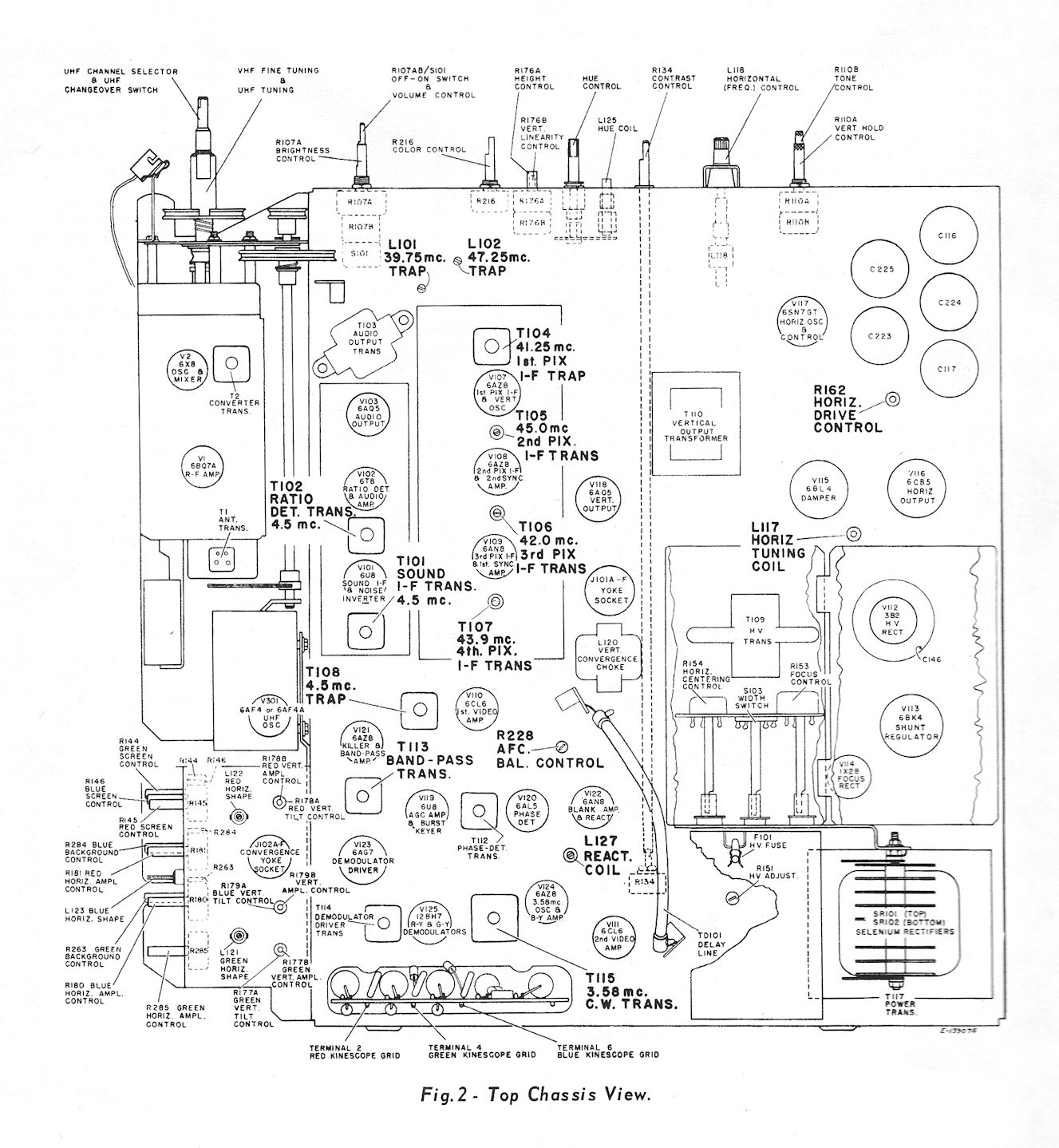
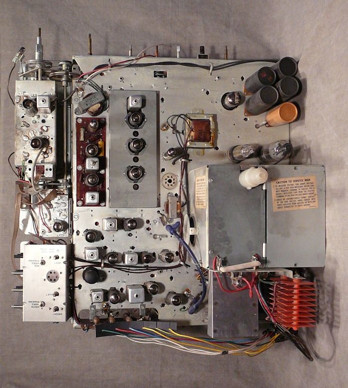
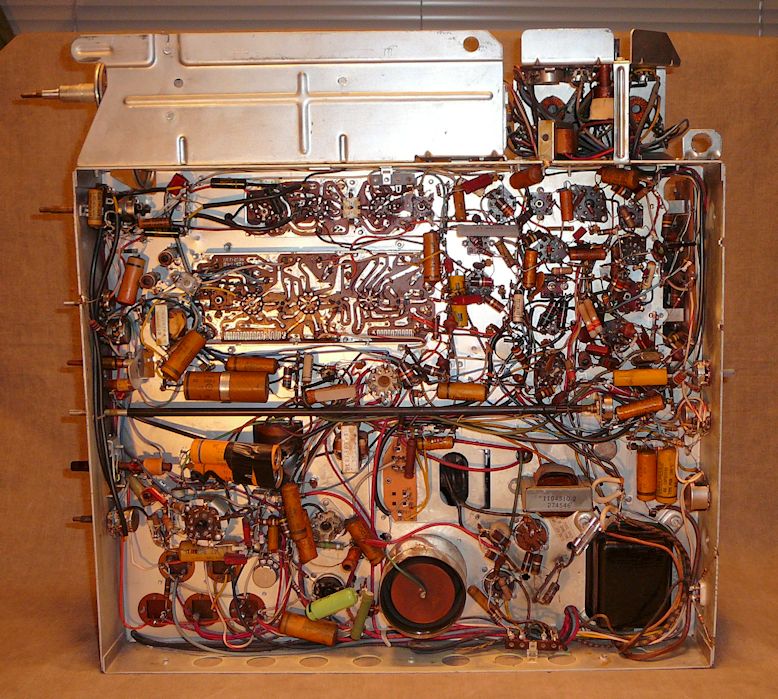
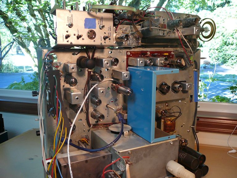
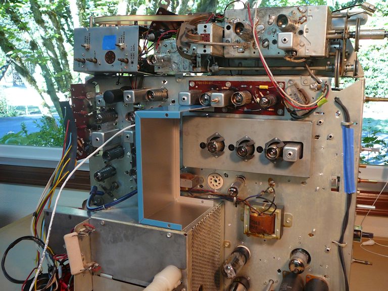
Here is the chassis layout diagram and a photo of my unrestored CTC-4 chassis for comparison:


The CTC-4 television uses 26 tubes:
| Tube |
Type |
Function |
| V1 |
6BQ7A |
RF Amplifier |
| V2 |
6X8 |
Mixer / Oscillator |
| V101 |
6U8 |
Audio IF Amp / Noise Inverter |
| V102 |
6T8 |
Ratio Det/AF Amp/AGC Clamp |
| V103 |
6AQ5 |
Audio Output |
| V107 |
6AZ8 |
1st Video IF Amp / Vert Osc |
| V108 |
6AZ8 |
2nd Video IF Amp / Sync Amp |
| V109 |
6AN8 |
3rd Video IF Amp / Sync Sep |
| V110 |
6CL6 |
1st Video Amplifier |
| V111 |
6CL6 |
2nd Video Amplifier |
| V112 |
3B2 |
High Voltage Rectifier |
| V113 |
6BK4 |
High Voltage Regulator |
| V114 |
1X2B |
Focus Rectifier |
| V115 |
6BL4 |
Damper |
| V116 |
6CB5 |
Horizontal Output |
| V117 |
6SN7GT |
Horiz Oscillator & Control |
| V118 |
6AQ5 |
Vertical Output |
| V119 |
6U8 |
AGC Amplifier / Burst Keyer |
| V120 |
6AL5 |
Chroma Sync Phase Detector |
| V121 |
6AZ8 |
Color Killer / Bandpass Amp |
| V122 |
6AN8 |
Blanking Amp / Chroma Ref |
| V123 |
6AG7 |
Demodulator Driver |
| V124 |
6AZ8 |
3.58-mHz Osc / B-Y Amp |
| V125 |
12BH7 |
G-Y Demodulator / R-Y Demod |
| V126 |
21AXP22 |
Color Picture Tube |
| V301 |
6AF4A |
UHF Oscillator |
You can download the Sams CTC-4 service manual
(314-9)
from the Early Television Foundation schematic archive and get additional information
on their CTC-4 page.
In 1956, RCA published a 91-page book about servicing the CTC-4 television. This comprehensive
guide, which contains full schematics and dozens of illustrations, was given to repairmen who attended
the RCA CTC-4 service clinic. It could also be purchased separately. To download this
74-megabyte document, right-click on this icon and choose Save Target As:
In 1957, RCA published a Service Data Supplement for the CTC4 series, listing various production
changes. It added many waveform photographs, service tips, and "see-through"
illustrations of components on the video and audio printed circuit boards.
A fourth source for CTC-4 technical data is RCA's Field Service Guide for Color TVs, 1955-1966.
It contains eight large (11x17) pages that summarize key information from the service clinic book and service
supplement.
RCA's service clinic book and the field service guide provide separate schematics for
"early" and "late" production CTC-4s, along with diagrams and descriptions of specific
changes. The Sams manual provides a single schematic. If you are restoring a CTC-4, I'd
encourage you to compare your set to every available schematic and take notes as you go,
rather than rely in a single source.
Finding a CTC-4
While scanning craigslist ads one day, I noticed a rummage sale that included an RCA
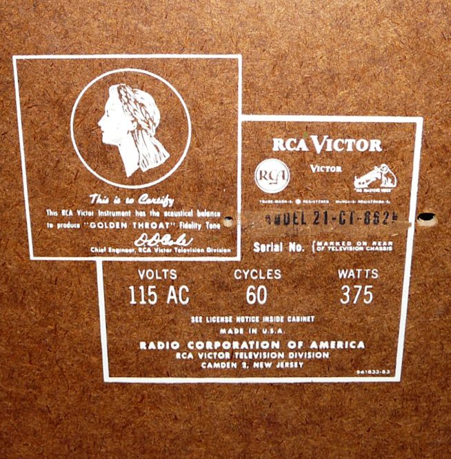
model "21-CT-852" television. RCA never made a TV with that model number, but the photo looked like a
model 21-CT-662U, the CTC-4 in a mahogany Director cabinet.
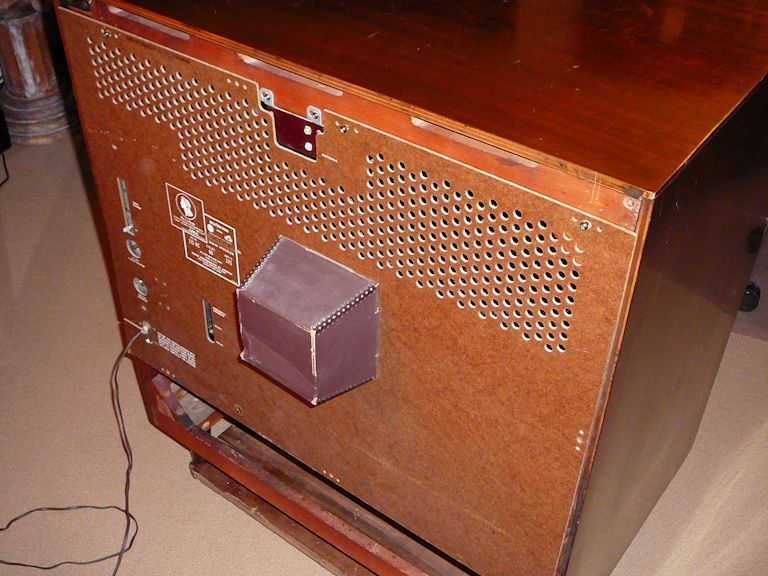
I made a beeline for the sale, a fund-raiser for a local pet shelter. Here's my first view of the
CTC-4 there:


The TV looked complete, including the back cover and detachable top cover, which I
removed for the second photo. A scratch on the back cover made the model
number (21-CT-662U) hard to decipher, so we can forgive the seller for garbling that.

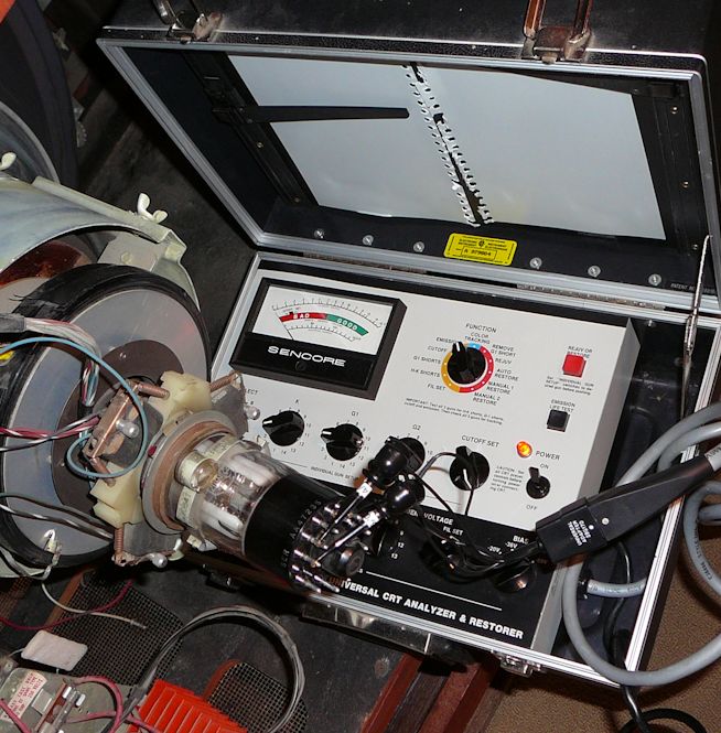
I had brought along my Sencore CR-70 CRT tester but its results were inconclusive.
The 21AXP22 CRT's heater had continuity according to my ohmmeter, but when I connected
the CRT tester and turned it on, the tester's filament voltage level sank and
the CRT failed the emission test.
Perhaps this CRT is good, perhaps it's a dud. With some doubt in my mind, I offered the
seller $80 and my offer was accepted. Even with a dead picture tube, the TV was well
worth that amount.
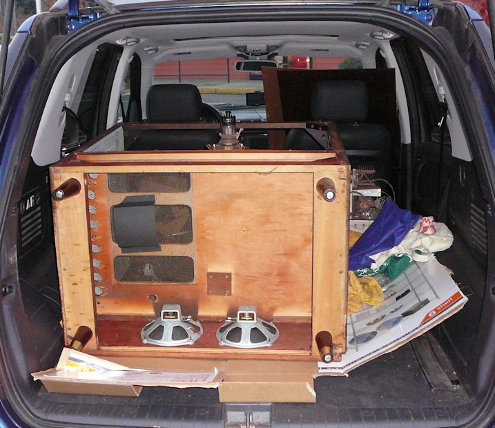
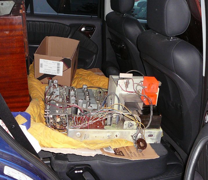
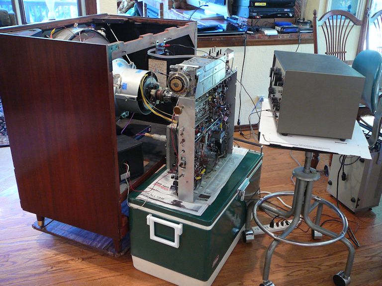
This console is too tall to fit standing up inside the back of my SUV. When I bought my
CTC-7, a shorter and wider console, that one had
barely cleared the ceiling standing up. To make this one easier to load, I removed the chassis
and laid the cabinet face-down in the back of the vehicle.


First Look
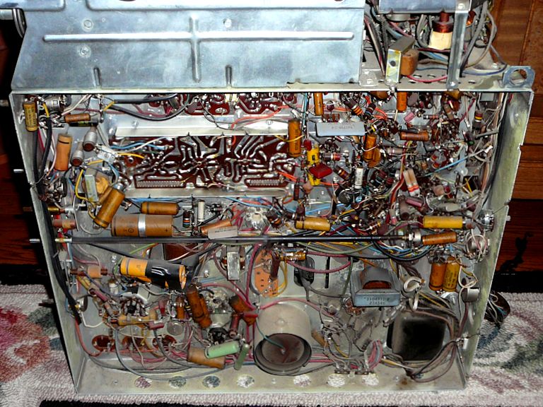
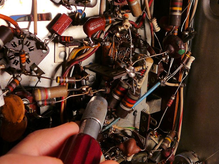
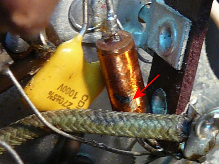
After unloading at home, I got a look under the chassis. A few capacitors were replaced
in the past, notably the pair of yellow electrolytics hastily wrapped
with black tape.

I was told that this one-owner local television had never left the lady's
living room. Apart from dusting, the chassis was remarkably clean.
I wouldn't be able to start restoration for a while, so I put the chassis back into
the cabinet for the time being.

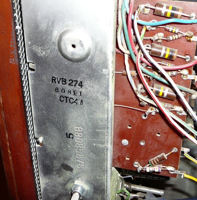
The back of the chassis bears a CTC-4A model number stamp and
the serial number B8085878.

I love having the correct back cover!

The TV's exterior is in nice original condition. The knobs are all present and
correct. The hinged "pencil box" control cover is in fine shape, and the
cabinet top only has light wear marks, which I can fix by reflowing the lacquer finish.
The Deluxe emblem in the lower right grille is often found damaged, but this one looks intact.
A little repair should take care of the minor grille cloth boo-boos.
There's also a small dent in the brass trim strip below the picture tube bezel. I'm
hoping that I can simply push it out after removing that piece. If it's still visible,
another trick is to swap the top and bottom brass pieces. (The dent will be less noticeable on top
because you view the trim piece from a different angle.)
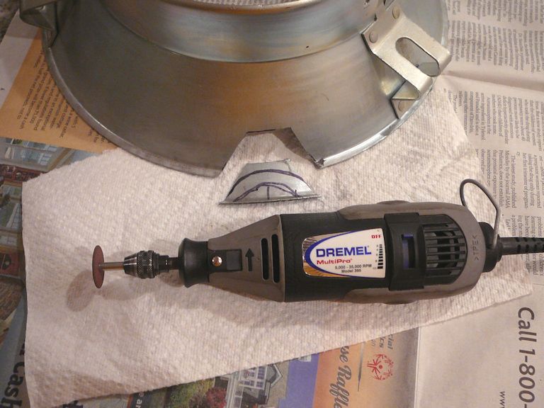
Testing the 21AXP22 Picture Tube
After doing a little more cleaning, I brought out my CRT tester for another check.
The signs were discouraging:

When I turned on the tester, the heater voltage dropped from 6.3 volts
to around 3 volts and the tester made a whining sound, as if its power
supply were unhappy. The CRT passed the G1-shorts and H-K shorts tests, but
the needle didn't move at all for the cutoff and emission tests.
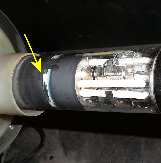
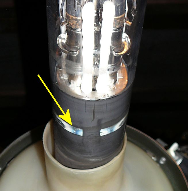
When I consulted the
VideoKarma forum, it was suggested
that the tube had lost vacuum, a condition that can be checked by observing
the getter flash in the tube's neck.
The getter is a deposit of metal (often barium)
that adsorbs—"gets"—the last stray molecules of gas inside a tube
after it is evacuated. In a healthy tube, the getter material is opaque and shiny.
In a long-used tube, the getter can become thin, nearly transparent.
If a tube loses vacuum and admits air, the getter immediately turns white with oxidation.
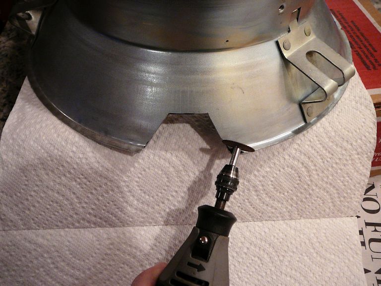
I removed the yoke and other components from the tube neck to view the getter, visible
through these slots above and below the neck.


The milky white getter shows that the tube has lost vacuum. My CRT is a dud!
As one Videokarma member pointed out,
air has been present for so long that some of the gun elements are visibly corroded.
Although the heaters are still intact, if I continued to power the tube with
air inside, they would soon burn out.
Like the
15GP22 CRT used
in the CT-100, the
21AXP22 was only
manufactured for a short time, and many of the survivors have
succumbed to leaks, as mine has. I am not the only CTC-4 owner with a dead 21AXP22.
In the heyday of tube television, CRT rebuilding was a cottage industry throughout the
USA and this tube could have been rebuilt to function like new. (In a nutshell,
rebuilding involves cutting the tube's glass neck, replacing its metal gun assembly,
installing a new neck and base, and re-evacuating it.)
Unfortunately, the last rebuilder in the world went out of business in 2013.
Although the Early Television Museum in Ohio has a
project underway to rebuild
vintage tubes, that service won't be available for a few years.
Until rebuilding becomes available, my best option is to adapt another twenty-one inch color CRT
for this set. A helpful Videokarma member offered to sell me a spare 21FJP22 tube,
which should be usable with some mechanical modifications. While I waited for that tube
to be delivered, I proceeded with recapping.
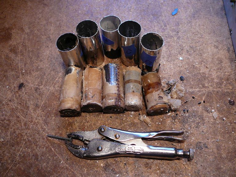
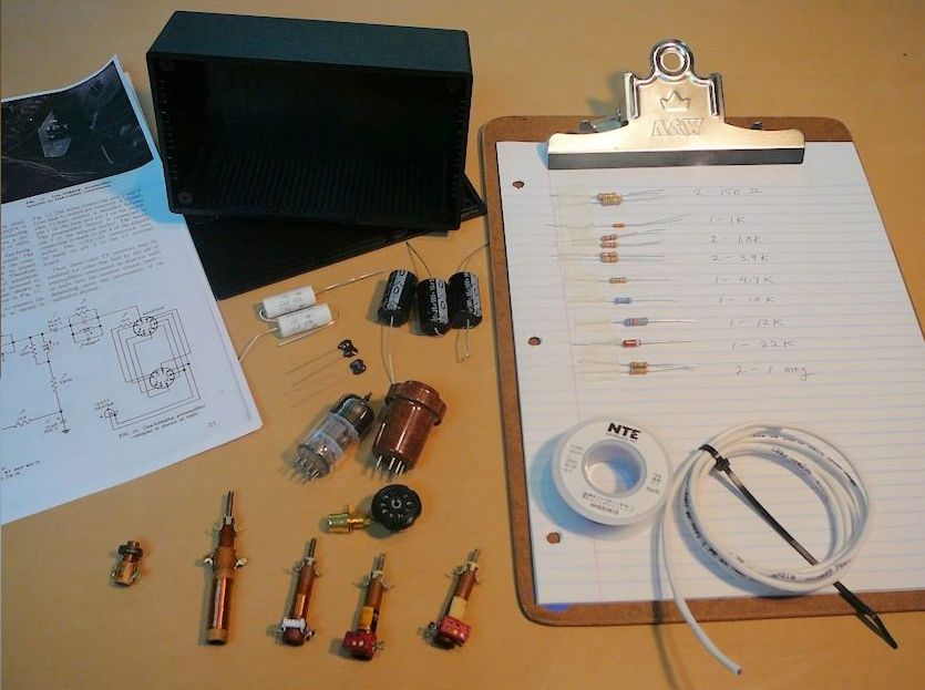
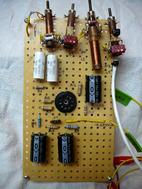
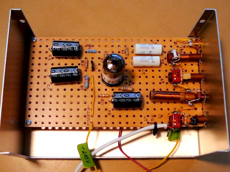
Restoration
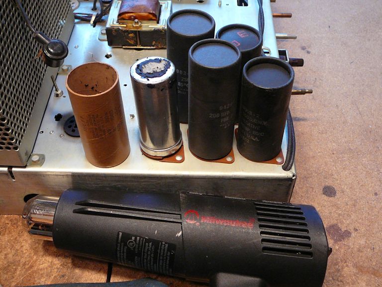
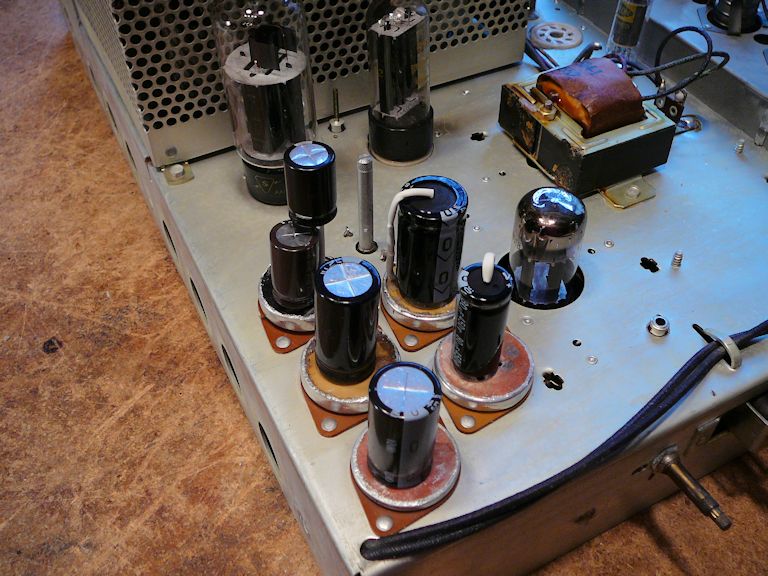
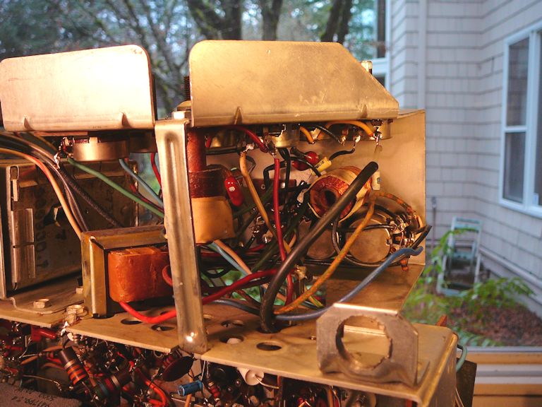
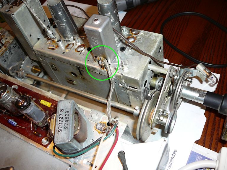
Here's the top of the chassis after brushing off some dust:
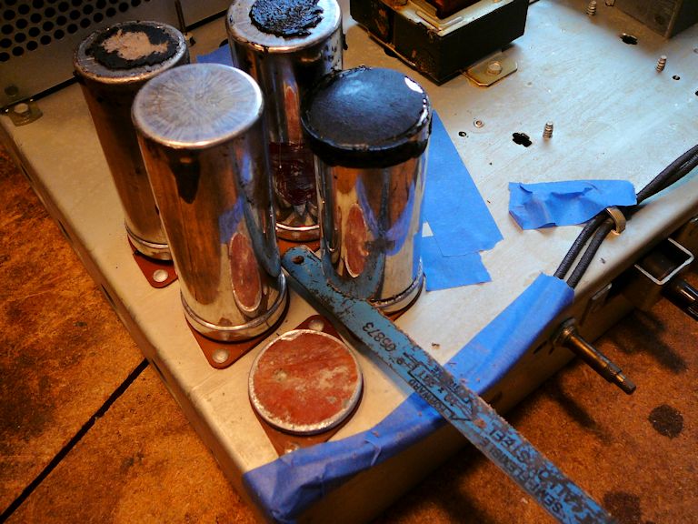
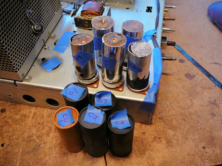
At the lower right you can see five electrolytic capacitor cans with black and yellow
cardboard covers. These contain the main power-supply caps, C1-C4 and C6. Replacing
those will be one of my first tasks.
At lower left in the previous photo are the two big orange selenium rectifiers.
Those will be disconnected and replaced with silicon diodes. I'll leave the old rectifiers in
place for appearance's sake.
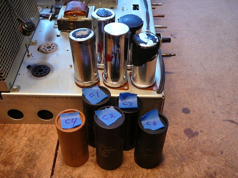
From the underside, we can see that the five can capacitor bases (at lower left) will be easy
to reach:

The five cans hold a total of eight capacitors, so I'll restuff the
cans rather than try to mount all of the replacements under the chassis. My
recapping article has a lot more information about restuffing
and other replacement techniques.
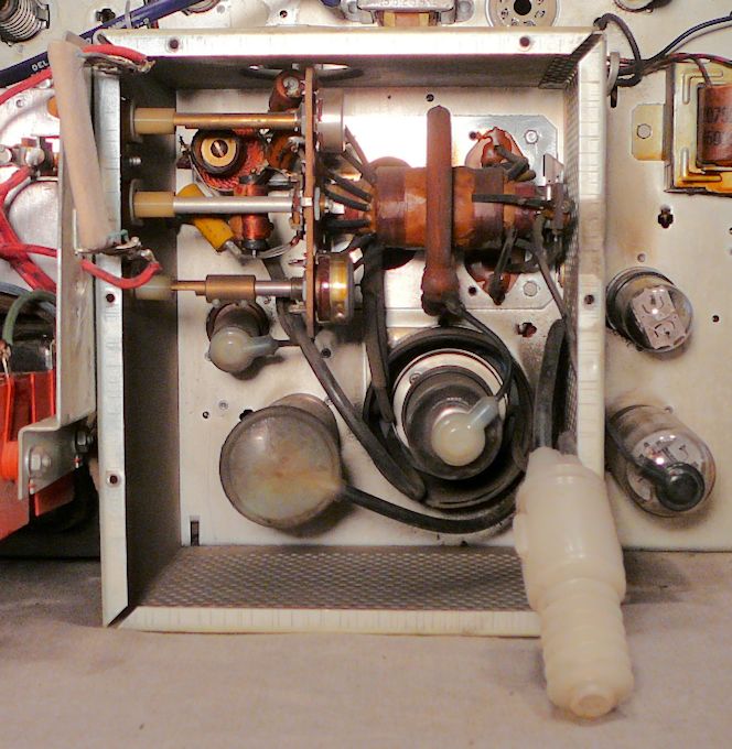
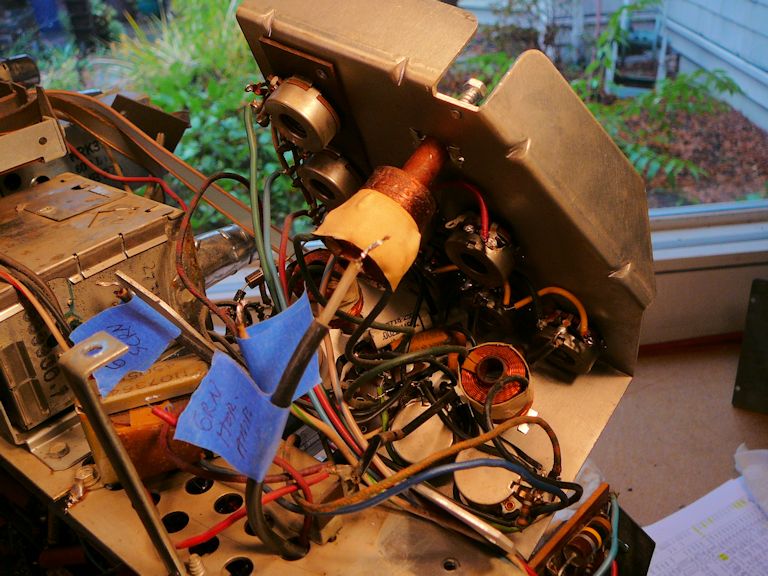
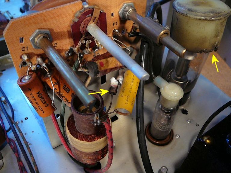
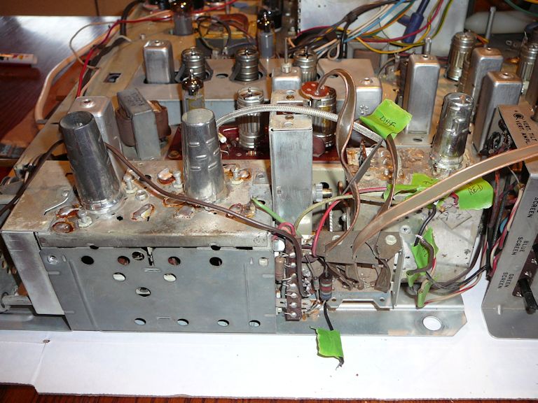
Inside the high-voltage compartment, the main components look good.

The all-important flyback transformer, the big orange component at upper right, looks
intact, with no dripped wax, and there are no signs of catastrophic short-circuiting.
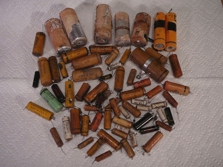
Replacing Capacitors
The first step in restuffing the electrolytic capacitor cans is to remove their
cardboard covers. After warming the cover with a heat gun to soften the tarry
adhesive, you can simply pull the cover off.


Cardboard covers provide shock protection on cans whose metal exteriors are not connected to chassis ground.
As you can see in these photos, such cans are mounted on fiber washers to isolate them from the
chassis.
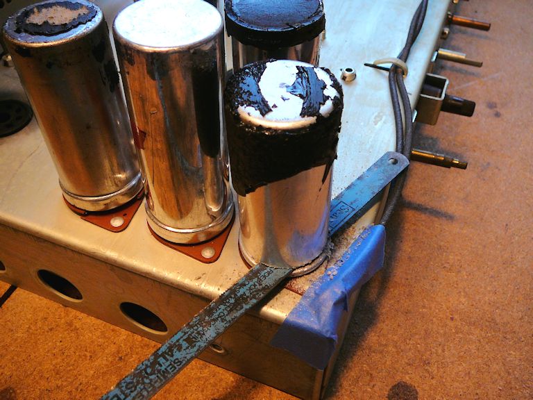
I'll cut the first can (C6) with a hacksaw blade held in my fingers. It's a little tricky when
the cans are mounted close together, but not too difficult if you take your time.


I'm using tape to protect nearby cables from the saw blade and to
cover chassis openings where I don't want metal filings to go.

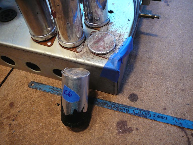
In the next photo, the cans have been cut at their bases (they are standing
upside down with their innards showing) and I labeled all of the
covers and cans. Each cut is unique, so if I can match each can to the right
base when reinstalling them, everything will fit neatly.

The next step is to remove the innards from each can. I screw a big wood screw
into the capacitor body, heat the can with a heat gun to soften the tarry adhesive,
and draw the body out.

In the next phase, I have mounted all of the new electrolytics,
routing their leads through tiny holes drilled in the bases so that I can
solder them directly to the original terminals underneath the chassis. An advantage
of this method is that you don't disturb the terminal wiring with a lot of
unsoldering and resoldering.

Later on, after I'm satisfied that the TV is operating normally, I'll epoxy the
cans back onto their bases and reinstall the cardboard covers. Then these caps will look
original, with fresh components inside.
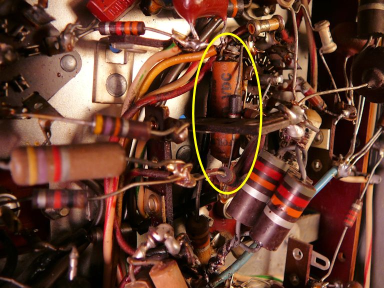
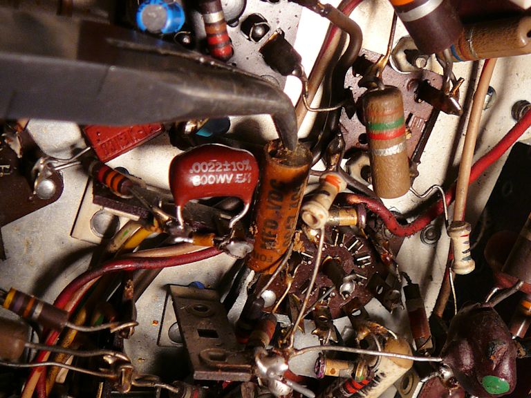
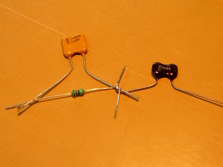
The rest of the electrolytics were straightforward, so let's skip ahead to a
tricky little non-electrolytic. Look at how this tan paper cap is buried under other
components.

It was impossible to reach the leads with a snipper without unsoldering other
parts, but I was able to sneak in the end of a little X-acto saw
and then draw out the old capacitor with pliers.


I connected the new cap to the same terminals on the tube socket, in a
more accessible location.

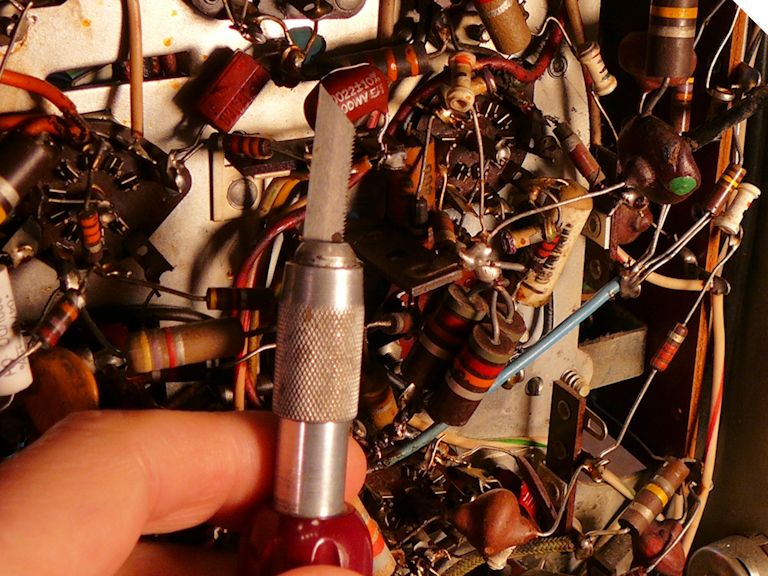
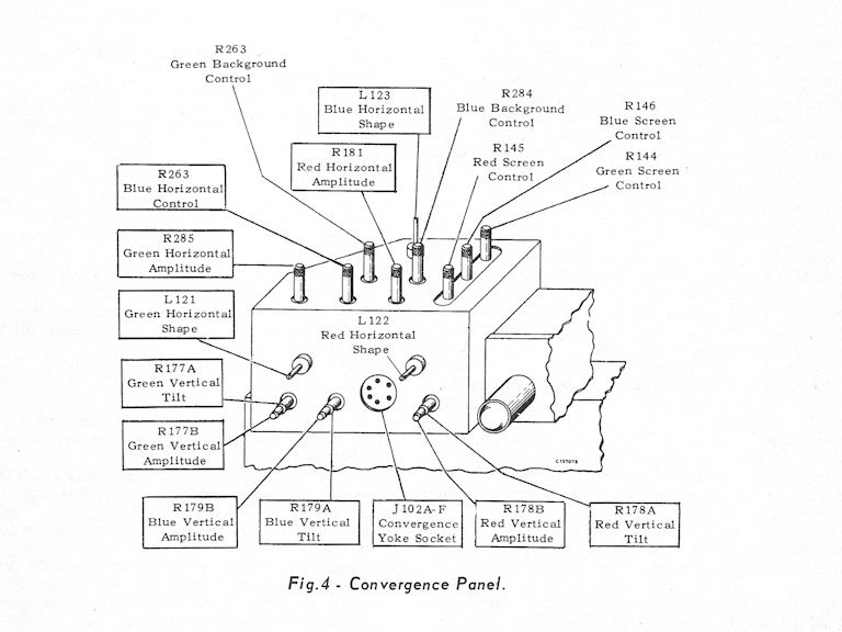
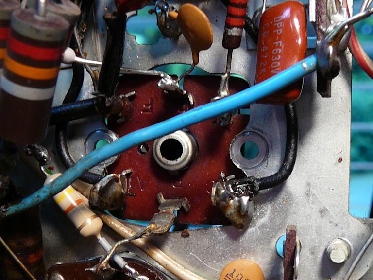
Under the convergence control panel you'll find a few more buried capacitors.
To gain access, you'll need to unsolder enough connections to tilt the panel up.


While the convergence panel is accessible, it's prudent to clean all of its
potentiometers and coil adjusters and replace any that are defective. Until all
of them are working correctly, your chance of getting a good color picture is
close to zero. This diagram shows the sixteen (!) adjusters on this panel:

Snip, solder, snip—eventually, we'll get all of these caps!

Uh-Oh
Things in the high-voltage cage had looked OK at first glance, but in the course of
recapping I removed the cage for a closer look. Uh-oh!

The burned resistor wasn't visible before. A little nudge showed that it was actually
broken in half. The 6BK4 HV regulator tube has a big plastic insulating crown that looks
blackened and chewed up by arcing. This looks a little scary, but perhaps there was only
a brief meltdown when someone powered up the TV after those electrolytic caps had failed.
I'll reserve judgment until I have replaced the resistor and the caps, cleaned
up the plastic crown, and given the set a tryout.
In case you're wondering, the three long-shafted controls shown in the previous photo are the
horizontal centering and focus potentiometers and the width switch. When the cage
is reassembled they will be accessed through slotted insulating covers. With voltage
in excess of 20 kilovolts, the designers took care to protect fingers from being zapped.
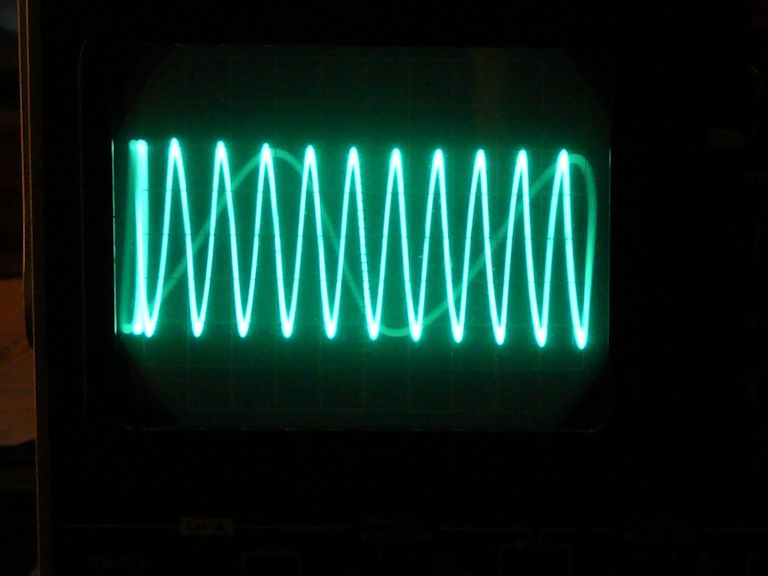
First Power
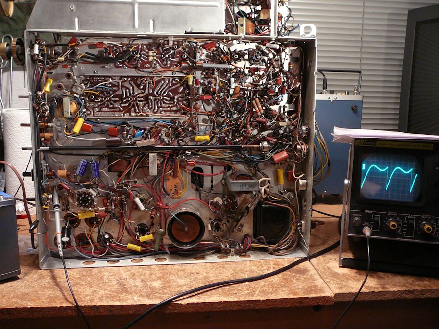
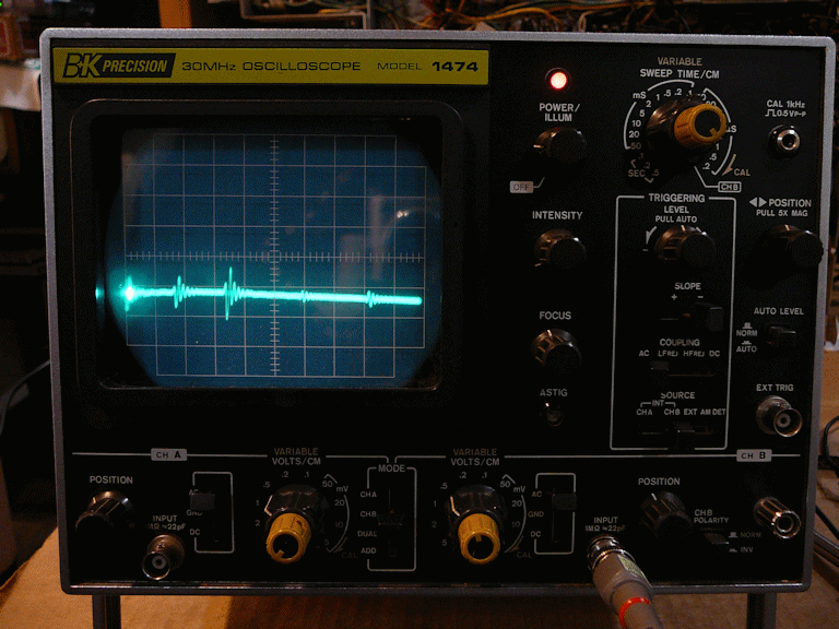
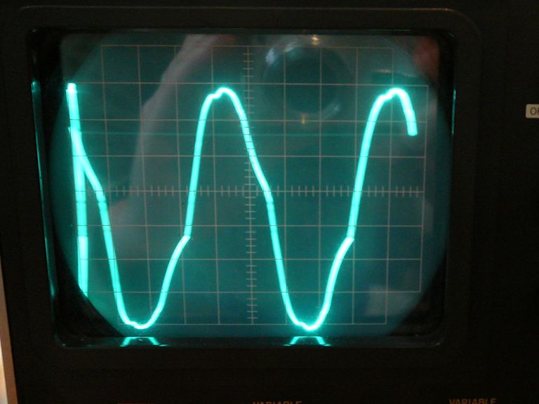
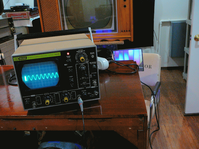
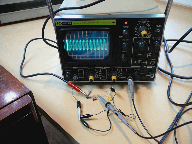
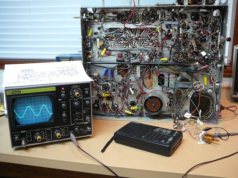
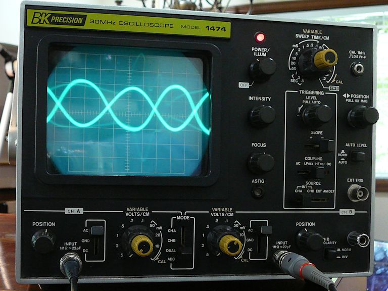
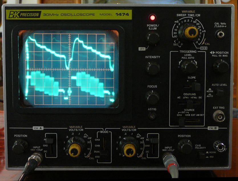
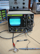
After hours of tedious recapping, I'm ready to apply power and the initial results are encouraging.
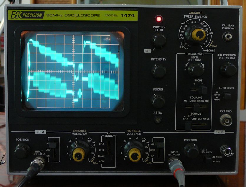
The basic voltages look reasonable and the chassis produces good-looking waveforms. In the
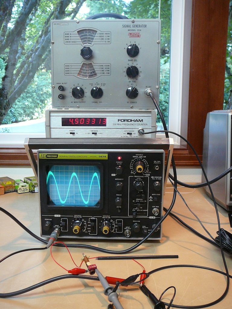
next photo, I'm looking at a horizontal waveform with my trusty old B&K Precision oscilloscope.
With a pattern generator supplying a color-bar signal, I also saw the expected
stairstep pattern at the video amp, and when I hooked up an antenna and tuned to
the channel used by my in-home
TV transmitter, I could hear decent audio, as well.
Too bad that my picture tube is dead—I have a hunch that this TV might be ready
to sit up and bark!
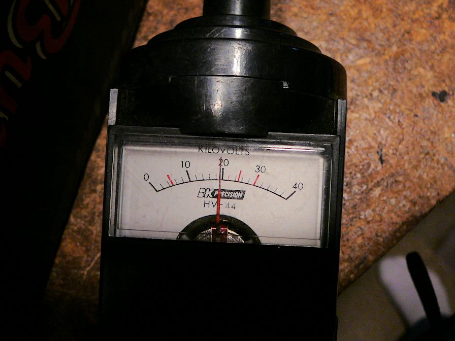
My HV meter shows about 19.5 kilovolts. That's a little low, but not bad, considering
that I haven't replaced the selenium rectifiers with silicon diodes or done anything
to tweak the HV level.

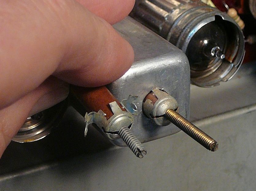
Speaking of high voltage, if you want to power the CTC-4 chassis on a workbench, you'll
need to insert a non-conductive tube to defeat its high-voltage interlock. (In normal
operation, the tube attached to the back cover performs this function.) I found
a plastic cap from a pen that fits just right.

I wish that more TVs had included this thoughtful feature. When
you withdraw the back cover for routine service, the interlock discharges any residual high voltage
from the picture tube, eliminating the possibility of a painful shock.
Finding a Substitute CRT
Voltages and waveforms are well and good, but without a usable picture tube, this TV will
never make a picture. Fortunately for CTC-4 owners, it's possible to replace the rare 21AXP22 picture
tube with a newer 21-inch color tube. After I mentioned this in the VideoKarma forum, a generous fellow
collector across the country offered a 21FJP22 CRT that he had salvaged from another
set. All that I had to do was ship it from the East coast to the West.
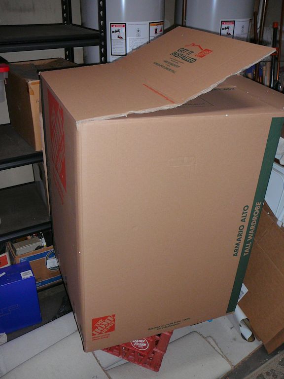
To simplify things at his end, I agreed to send him an empty box. I found a wardrobe-sized moving
box from Home Depot with square dimensions (24 x 24). That's ideal for a 21-inch tube with
some allowance for padding. I'll cut down the top to reduce the height.
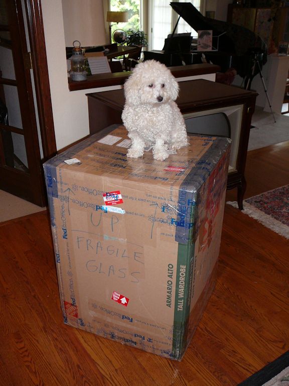
I lined the box with rigid Styrofoam sheets, put extra padding on the
bottom, made a collar to fit around the tube neck, and threw in a lot more bubble wrap
after the next photo was taken.

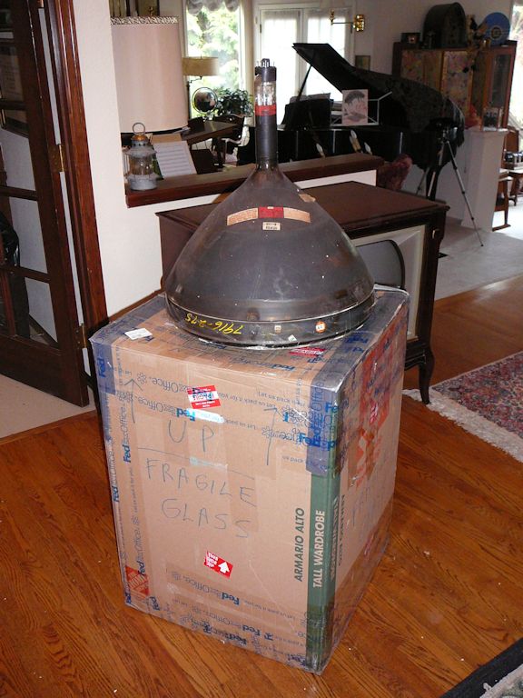
The next photos show the empty box on its way out, and as it returned a few weeks
later, with a CRT inside.

After unpacking, I can see that the CRT arrived safely. So far, so good!

Substituting a 21FJP22 for a 21AXP22 Picture Tube
Replacing a metal-coned picture tube with a newer 21-inch glass tube was a common
practice during the CTC-4's original service life. There were even factory kits to simplify
some conversions. My tubes are electronically compatible, so conversion takes only three steps:
- Adapt the physical mounting.
- Make a new HV cable to fit the new tube's second anode button.
- Add a grounding strap for the new tube's capacitive aquadag coating.
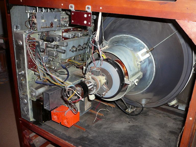
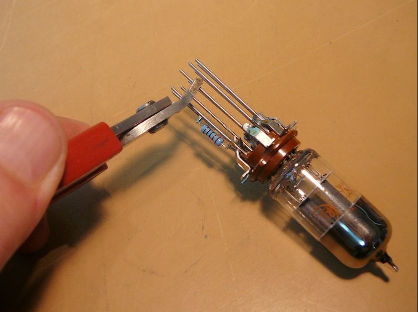
Removing the 21AXP22
I'll start by removing the old 21AXP22 and familiarizing myself with
its mounting and accessory hardware. Removal is easiest if you take out the chassis and
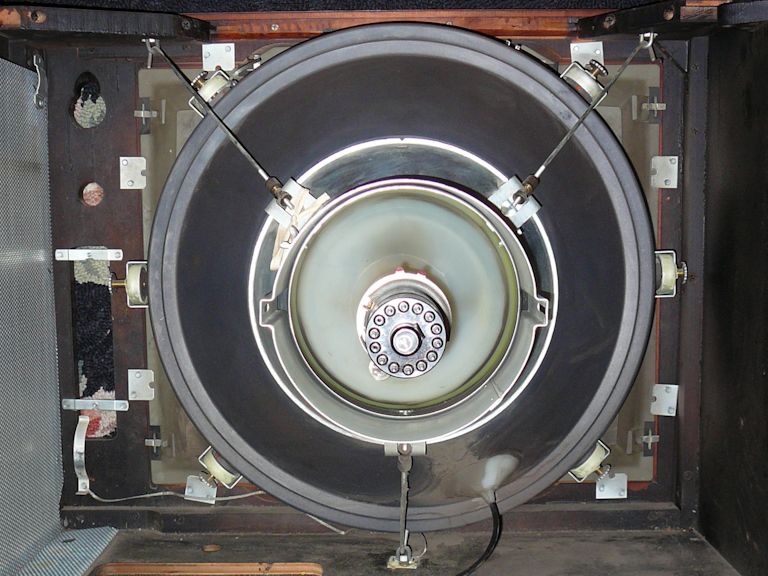
lay the television face-down on a carpeted floor. This photo shows the original CRT in the cabinet.

Just as in my RCA
CT-100, the CRT is held in place by three
steel retaining stays and a metal retaining ring. (The main weight of the heavy CRT
bell is supported by a stout collar in the front of the cabinet.) The stays can be lifted out after
loosening their thumbscrews. In this photo, the stays are gone and I am lifting
up the yoke support, whose three mounting screws have been removed:

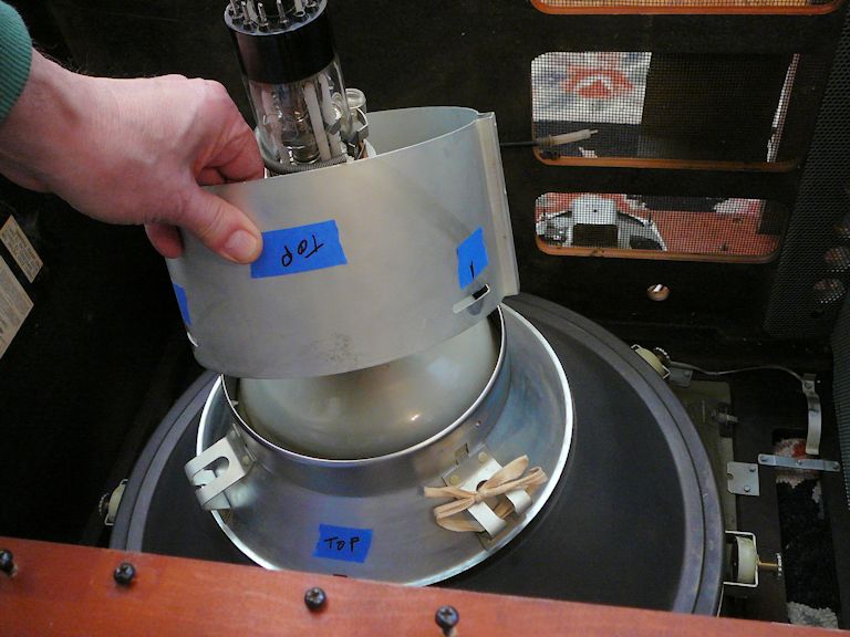
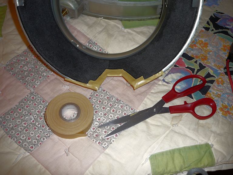
Encircling the CRT bell near the front of the cabinet is the field neutralizing assembly,
a large steel ring with six round adjustable magnets. In the next photo, I have begun
to remove this assembly, after loosening its clamp screw and a short grounding clip. The magnets
are the heavy round objects with knurled thumbwheels.

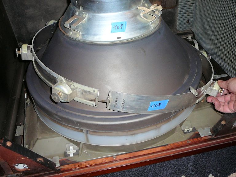
The metal cone of a 21AXP22 tube carries high voltage during operation, so the
cone and part of the neck are covered by a heavy plastic insulating skirt.
The next step is to lift off the plastic CRT skirt and the attached retaining ring.
There is an extra plastic insulating ring around the bell's largest perimeter, and
below the CRT you'll find a circular rubber gasket that fills the gap between the CRT
face and the support collar.
The next photo shows the original 21AXP22
CRT and its associated parts: yoke support, retaining ring, field neutralizing ring,
grey-and-white plastic skirt, black plastic insulating ring, and gasket.

Although it's nominally the same size as my replacement, the metal-coned 21AXP22 is much
lighter than the all-glass tube.
The parts to be reused in converting to an all-glass CRT
are the big round field neutralizing assembly, the steel retaining ring, and the round yoke support.
I'll store the insulating parts along with the CRT, just in case it becomes possible to rebuild the CRT
in a few years. At that point, I could retire the glass replacement and install the rebuilt
21AXP22.
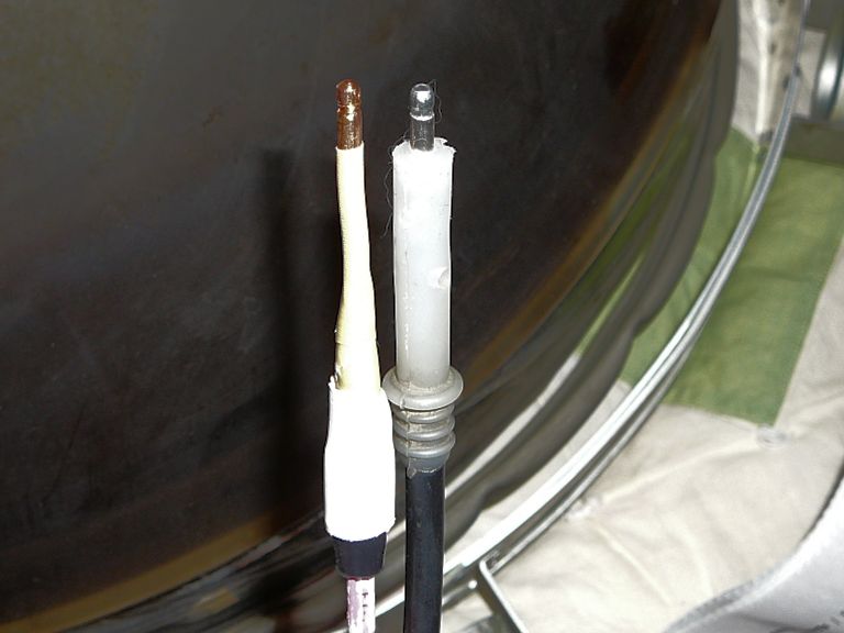
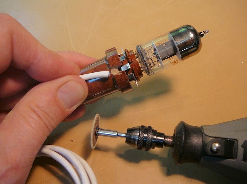
Making a New Anode Lead
My new glass tube takes a different type of anode connector, so I'll make a new one,
starting with this lead:

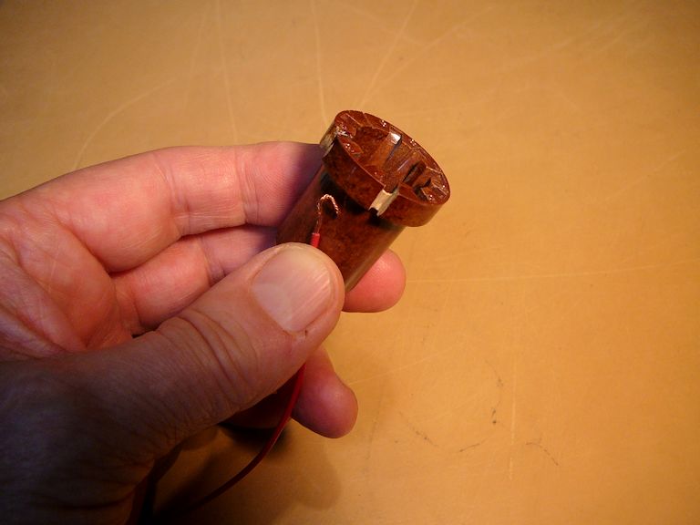
The other end of the factory lead has a heavily insulated tip that snaps inside a larger
insulated collar. I ground a piece of heavy copper wire to approximately
the same shape and then soldered it to the end of the new HV cable.


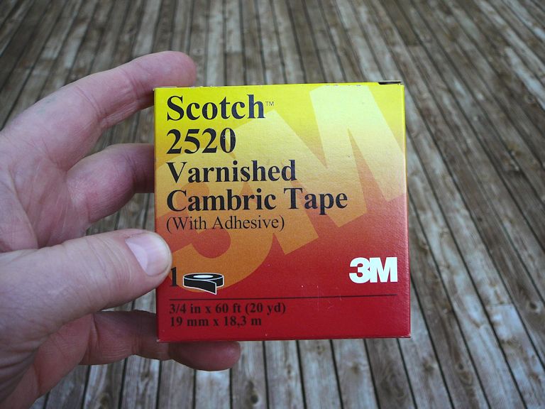
A little research turned up this varnished cambric insulating tape, rated
for 90 kilovolts.

For now, I wrapped the base of my connector with the cambric insulating tape.

I'll eventually come up with something more permanent, perhaps secured with epoxy
and coated with corona dope. Right now, I'm more focused on modifying the retaining ring
so that I can see my new picture tube light up.
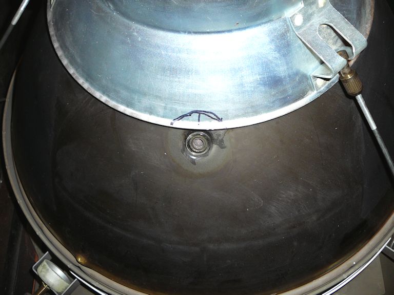
Adapting the Retaining Ring
Trying on the retaining ring over the new CRT shows you why it won't work without modification.
The ring is much too close to an HV connection that carries more than 20,000 volts. If you
installed the ring right over the insulating cup, the HV would arc straight through the
rubbery cup onto the ring.


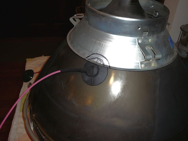
In the next photo, I have cut a small piece out of the retaining ring. I don't want to weaken the ring
by removing too much material. Let's see whether this size cutout works without arcing. I
can always enlarge it later.


Next, I applied multiple layers of cambric insulating tape to the cutout edges. The underside of
the retaining ring has a layer of spongy black material. I removed a little of that
around the edges so that I could add tape without making a lump that caused the ring to
fit unevenly.

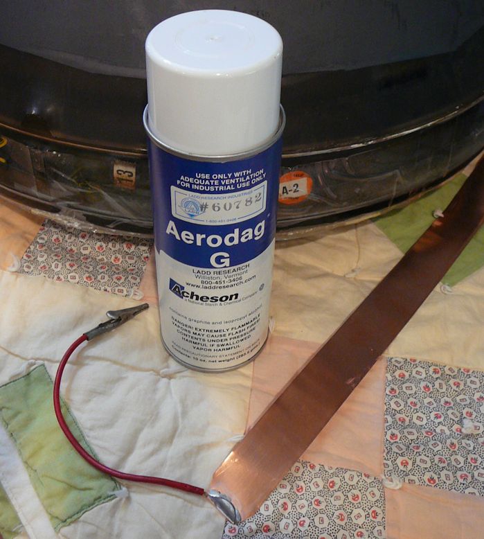
Aquadag
Unlike the original metal CRT, the glass 21FJP22 uses a conductive "aquadag" coating
to create a capacitive effect between the inside and outside of the tube. After cleaning
and masking the tube bell, I'll spray on a fresh coat of Aerodag G.

The aquadag layer must be grounded, so I fashioned a grounding strap from thin copper sheet.
I'll secure the strap with a long spring and clip its end to one of the nearby grounding points.
In the next photo I have cleaned the old aquadag layer and masked off the CRT bell to spray on
fresh aquadag.

The new 'dag dries within minutes. I applied a couple of coats; there's no need to skimp.

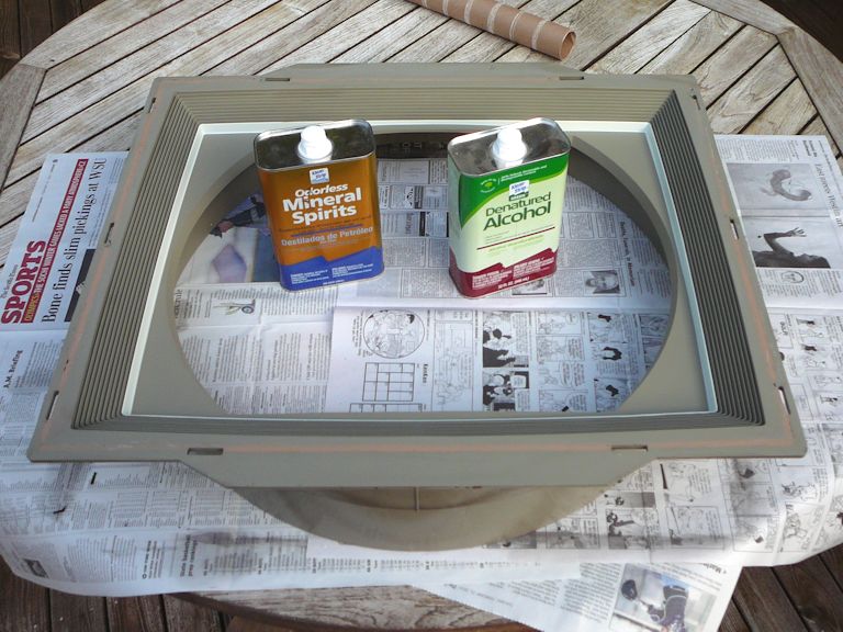
Cleaning the CRT Mask and Safety Glass
While I have the CRT out of the cabinet, it's an ideal time to clean the safety glass
and mask. The heavy glass is mainly supported by the cabinet opening, but its edges are also
covered with a black, sticky adhesive—perhaps to keep dust from getting between
the front of the CRT and the back of the glass. I scraped off the biggest
chunks and dissolved the rest with mineral spirits and denatured alcohol:


The mask is more than mere decoration. Its round inner collar supports most of the
picture tube's weight.
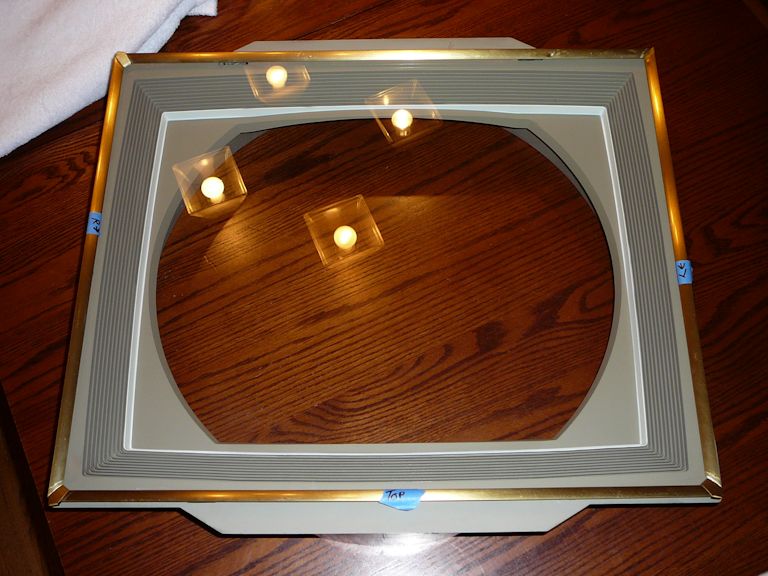
I temporarily reassembled the mask and glass with the trim, to admire my handiwork.

When these are installed in the cabinet, the trim parts are held
on by tabs that pass through slots in the cabinet and mask. Metal clips secure
the tabs on the inside.
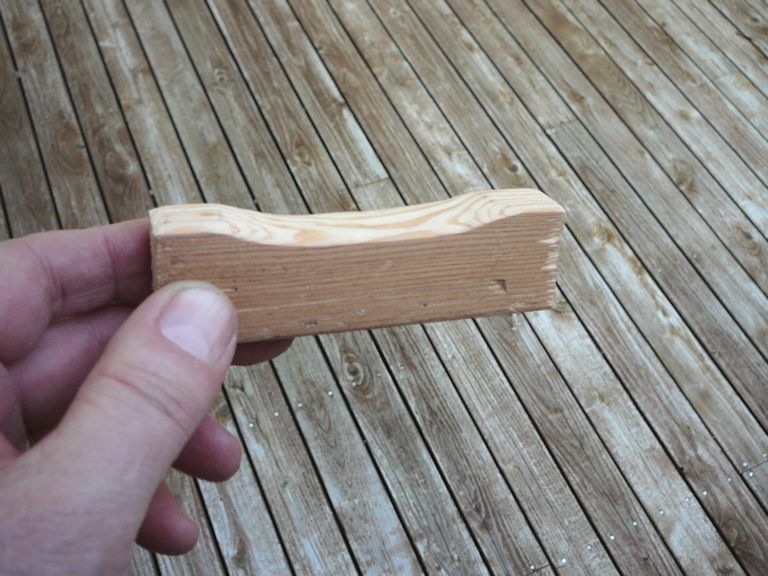
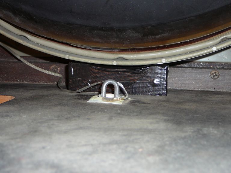
Reinforcing the CRT Support
This all-glass CRT is much heavier than the original 21AXP22, so I'll add a little brace under
its supporting collar. I fashioned the brace from wood and wedged it firmly in place,
covering it with black tape to make it unobtrusive.


I'm not being overly fussy here. A 1960s article about substituting newer glass tubes warned that
you might have problems with vertical centering and linearity if the mounting sagged under
the weight of the heavier glass tube.
First CRT Trial
After working on this television for a long time, I was itching to see whether it
would light up. I installed the recapped chassis and my new picture tube, secured
the aquadag grounding strap across the CRT bell, and cautiously powered it up.
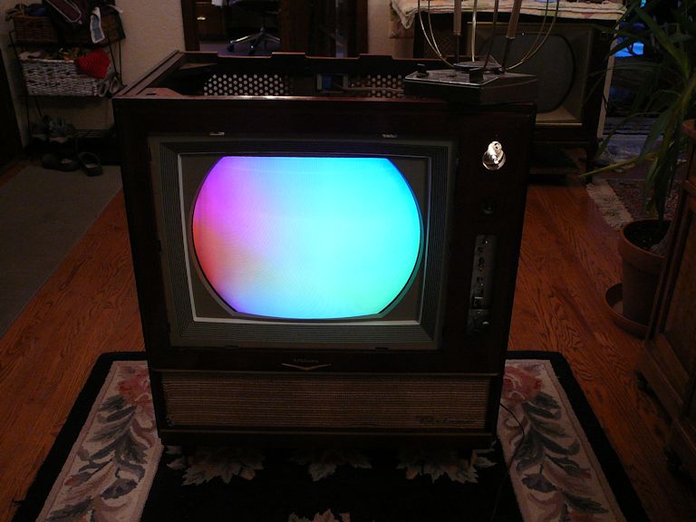
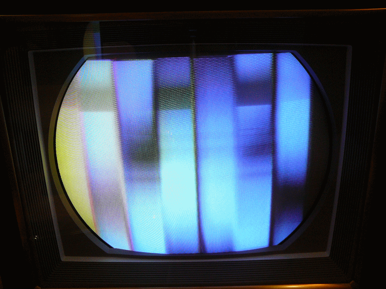
Hooray! The CRT looks nice and bright and it is displaying colors. The
blotchy colors indicate imperfect purity, but that's no surprise, since I haven't
yet adjusted the purity magnet tabs on the CRT neck or the field neutralizing magnets around
the bell.
Many circuits must be working pretty well to reach this stage. The low-voltage
and high-voltage power supplies are operational and we have good vertical and horizontal
stability. I previously heard the audio section working, so those were all positive signs.
Although I had connected a rabbit ear antenna in hopes of receiving a program from my
in-home TV transmitter, there was no semblance of
a signal, either video or audio.
I knew that parts of the TV could pass a signal, since I had heard sound on the workbench
and I also viewed a video test signal as far down the chain as the video amplifier.
Relapses are discouraging, but perhaps the cause is something simple like a failed
tube or a funky tuner.
To investigate further, I'll need to move the TV to a more convenient location. At
this time, my workshop was packed up for a house remodeling project and it was hard
to find work space (the previous photo was taken in our front entryway!).
In Search of a Lost Signal
When investigating a problem, I try to eliminate simple, obvious causes before
searching for more exotic things. I had previously tested all of the tubes, but I retested
all of them in the signal chain. I also recleaned those tube sockets, since it may take only
one funky connection to interrupt a signal.
The cleaning didn't improve anything, so I moved the TV to a slightly less inconvenient location
(our kitchen) and prepared for some testing under power. Propping the chassis on a cooler behind the cabinet
allowed me to connect the CRT and see the screen.

There are various ways to investigate a no-signal condition. One method would be to start
at the source—the antenna terminals—and work your way downstream, checking
each stage with an oscilloscope to see how far the signal was carried before it disappeared.
Alternatively, you can start at the opposite (output) end and work backward,
injecting signals at the video amplifier stage and then the IF amplifier stage,
to see whether they were working.
I decided to begin at the output stage and work my way back.
First, using a pattern generator, I injected a video signal at the grid of the video
output tube (V111 in RCA documentation). An image appeared on
the screen, which told me that everything downstream from that point was operational:

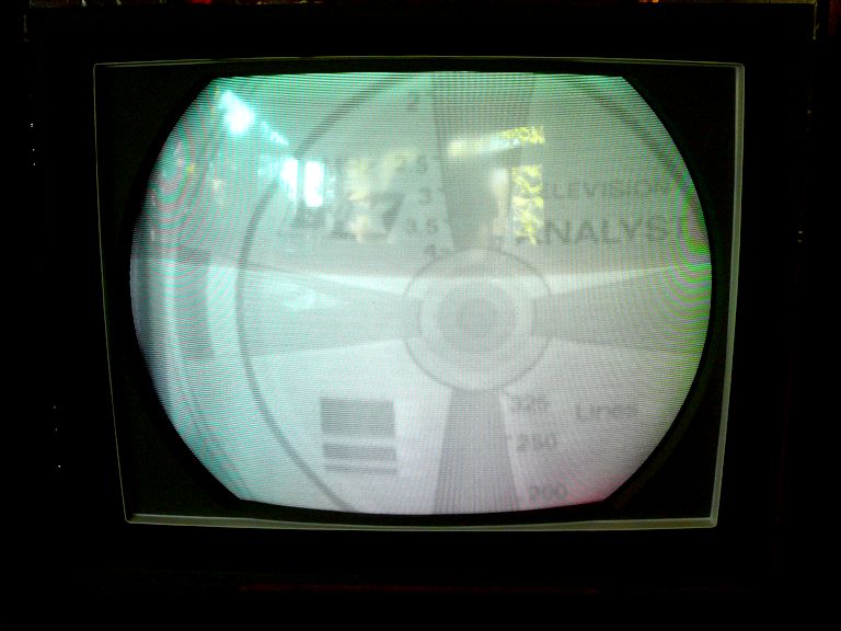
Next, I moved back to the grid of the first video IF amplifier (V107). Injecting a signal here will tell me
whether the IF stage works. This stage requires a signal at the
TV's IF frequency, so I used my BK Precision 1077B TV Analyst.
The image made it down the signal chain and appeared at the CRT:

These images weren't glorious, but
at this point all I cared about was whether a signal could pass through a stage,
and now I had eliminated a big chunk of the television from the equation.
The no-signal problem must be located somewhere between the antenna terminals and the
input to the IF amp—in other words, in the "front end" containing
the tuner and RF amplifier.
That's rather good news because the passive components in a tuner (coils, mica caps, etc.)
are usually very reliable. The most likely cause of trouble is dirty or oxidized
contacts in the tuner mechanism, so the obvious next step was to clean the tuner.
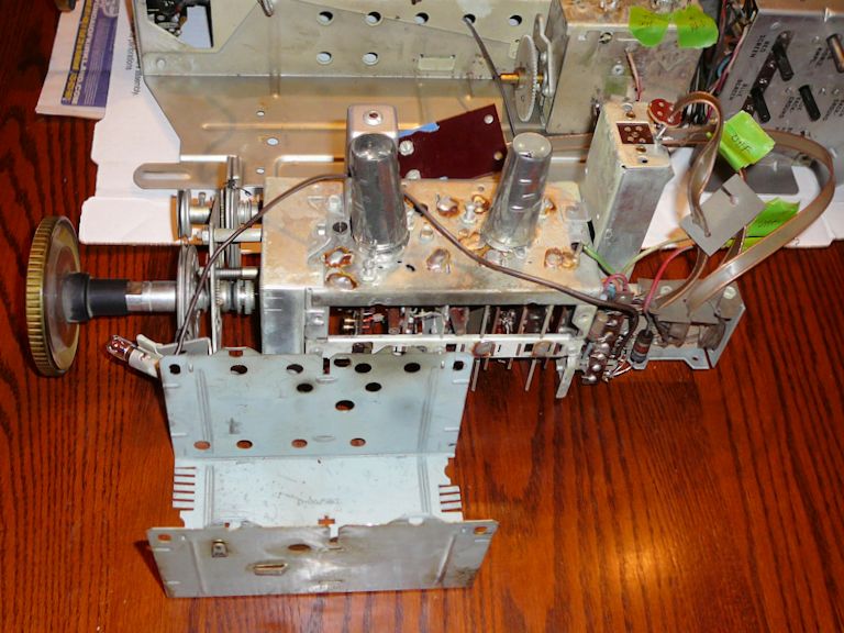
Removing and Cleaning the Tuner
On some TVs you can clean a tuner's contacts without dismounting it from the chassis, but
the CTC-4 isn't built that way. The contacts are enclosed in a shield that's impossible to
remove until you take out the tuner as a unit, which involves unsoldering ten
connections.
The tuner assembly consists of two separate tuners on one
frame, with a little cam-actuated switch to select either VHF or UHF mode. In the
next photo, I have begun to unsolder wires, labeling each with a tag.

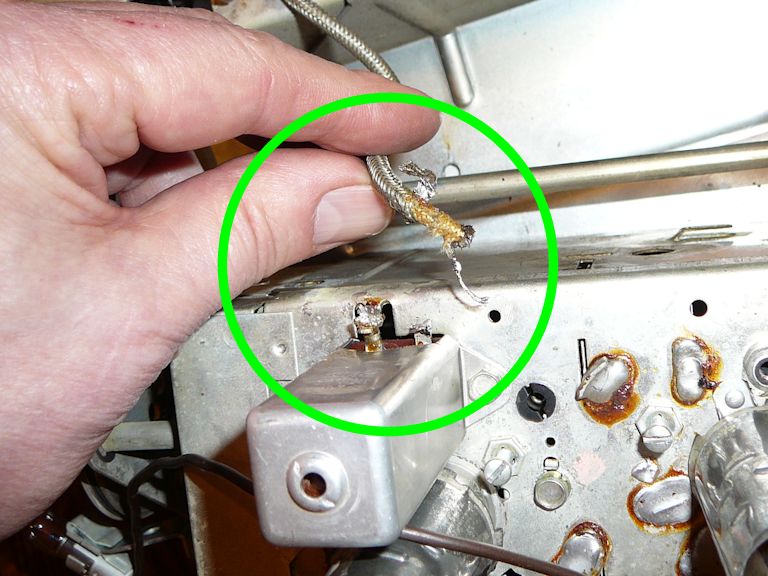
The signal output from the front end to the IF amplifier passes through the shielded
cable marked with green in the next photos. When you unsolder the shield and signal wire
from the chassis, use care not to mangle them.


In this photo, I have dismounted the tuner assembly and removed its cover to
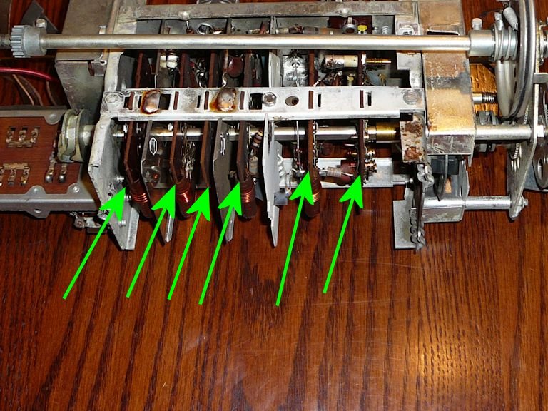
gain access to the switch wafers inside:

In this kind of tuner, rotating elements attached to the shaft make and break connections
with stationary contacts mounted on a series of phenolic wafers, which are marked with arrows
in the next photo. (The contacts are largely obscured in this view.)

When faced with a tuner like this, it's tempting to hose it down with a bunch of spray
cleaner and then switch it through all of the channels a bunch of times. That's a terrible idea!
Soaking the phenolic wafers with cleaner may create worse problems than the one you're trying to cure,
and if everything is covered with cleaner residue, that may attract dirt.
You should also avoid using anything abrasive on switch contacts, since that may destroy
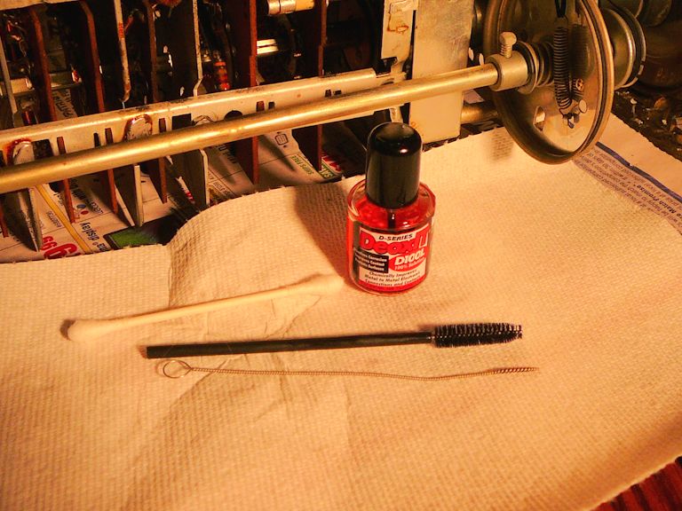
precious-metal plating. I clean each contact individually, using liquid DeOxit and a non-abrasive
tool like a Q-tip swab or soft plastic brush.

The photo also shows a little stainless steel brush (available from CAIG) that I had used
earlier to clean tube sockets.
After cleaning the switch contacts and lubricating the tuner's rotary bearings, I turned my attention
to the VHF-UHF switching mechanism. The next photo identifies a rotating cam with a channel
that pushes a pin in and out when you go between VHF and UHF.

That pin is connected to contacts that slide along the phenolic slab to the left. In the photo, I had
just applied a dab of white grease to the pin, which I would spread around the cam's
channel with a Q-tip.
When I tried to operate the switch, I saw immediately why I had lost the
signal from the VHF tuner. The sliding contacts were cruddy with dried lubricant or plain
old dirt and they tended to stick in the UHF position, which probably hadn't
been used in many years. That completely interrupted the VHF signal.
The next photo is an animated .GIF that illustrates how the switch worked
after I cleaned and lubricated it. Notice how the contacts slide back and forth
as the cam rotates:
As with many little restoration mysteries, the problem was easy to cure—once I had
discovered the cause! You can reach the VHF-UHF switch without removing the tuner, but I always
clean and lubricate the tuner sooner or later, so it was not time wasted to pull it for service at this stage.
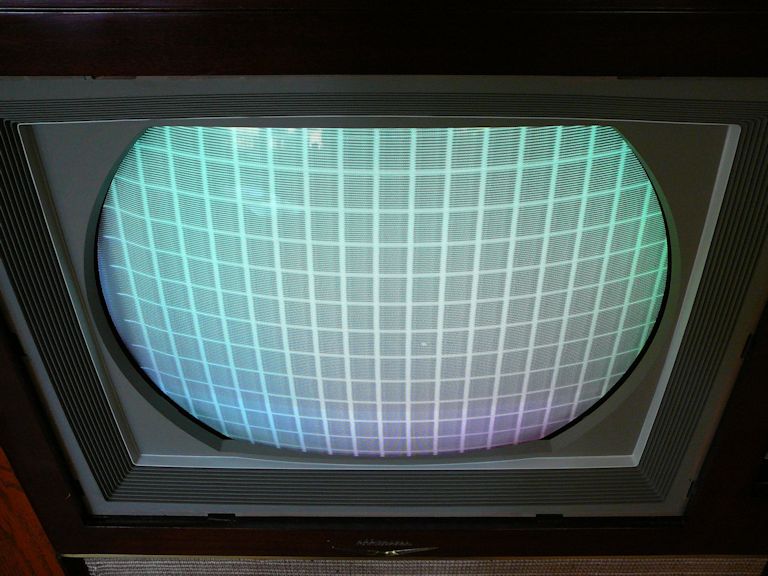
First Coherent Images
When I reinstalled the tuner and put the chassis back in the cabinet, I got
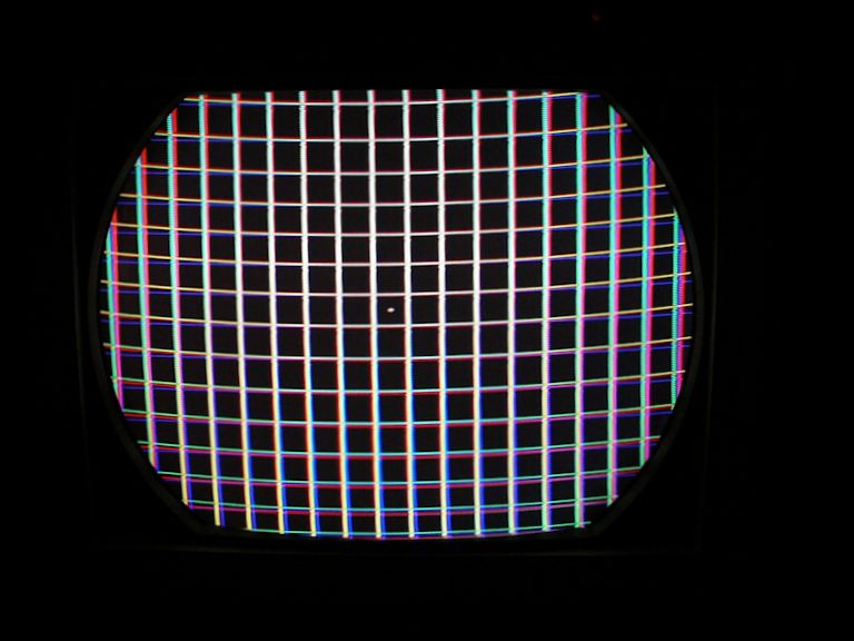
a bright, clear test pattern in VHF mode.
This crosshatch pattern isn't too shabby. The horizontal centering and linearity need adjustment,
and the separate vertical green stripes tell us that the dynamic
convergence needs work, but that's not surprising, considering all of the surgery that this
TV has undergone.
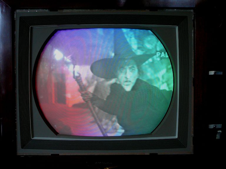
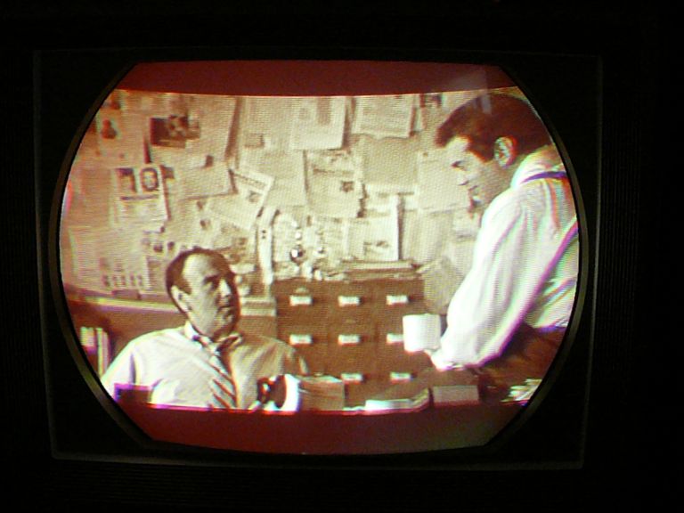
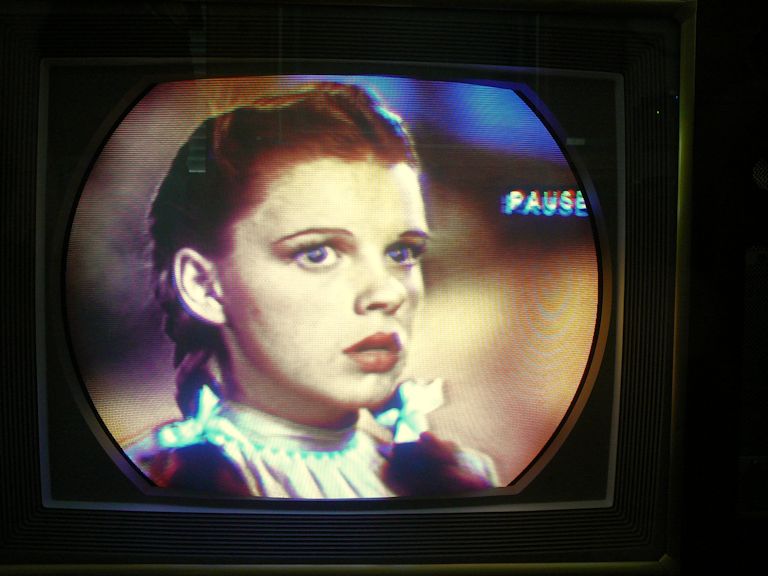
I couldn't resist dialing up the Wizard of Oz, just to see what a real program looked like.

Ignoring color for the moment, this is a fairly watchable picture. At least, the witch looks
like a witch! And the horizontal centering and linearity issues that we noticed in
the test pattern don't matter much when viewing an actual program.
Just as when the CRT first lit up, the large blotches of color tell us that the purity
needs help. Purity is only one of many adjustments in the full-dress
setup procedure, and it's fanciful to expect a luscious color picture when you
haven't begun that process.
Preliminary Color Setup
After our remodeling project was done, I was able to set up my workshop again and
return to some projects. I was eager to see a true color image on this TV, so I began
the color setup.
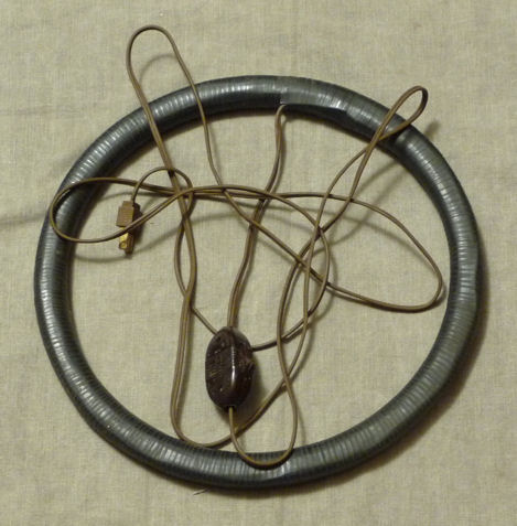
Before turning any adjusters, I degaussed the picture tube with my trusty old degaussing
coil. You can read more about degaussing in my CTC-11 article,
including photos that show a TV that needs degaussing.

Next, I adjusted the purity. I was quite curious about this step, since, as
we saw in the previous Wizard of Oz image, the purity was defective.
Instead of combining colors correctly for every detail, the screen
showed wide color splotches across a scene detailed in monochrome.
Furthermore, I was using a replacement 21FBP22A picture tube, not an original 21AXP22,
and I wasn't sure how the six concentric purity magnets around the CRT would work with
the newer glass tube.
When setting purity, you begin with a red screen, since if red is adjusted properly,
blue and green are easy to adust. The goal is to obtain a screen with
an even color, not contaminated by any other shades. The results were encouraging.
No absence of color here!


The next phase was convergence, which is usually time-consuming and
tedious. (Again, my CTC-11 article gives more details
about this procedure.) As often happens, it was much easier to
get good convergence in the screen's center area than around the edges:

In the previous photo, the center dot and the lines near the center are colored white, a result of good convergence.
In those areas, electrons from the red, green, and blue guns of the picture tube are landing precisely on the
same dots; mixed in the right proportions, those three colors produce white. As you move toward the edges
of the screen, you can see red, green, and blue lines diverging, the result of imperfect convergence.
Edge convergence is the Achilles heel of many a 1950s color TV. This test pattern looks mediocre, but
it's not bad for a first pass. I can return to convergence later on, when I'm certain the
TV is basically operational.
Eager to see a true color picture, I attached a pair of rabbit ears and tuned in a broadcast from
my in-house TV transmitter. The result was disappointing:

After all this work, my color TV only shows black and white!
I quickly checked the other controls that play a part in the color display: the Color and Hue controls, AGC adjuster,
color killer, noise threshold adjuster, and fine tuning. All of them worked as expected, but the fine tuning seemed to be off-center
for every channel. Turning it fully counterclockwise, I could change the tuning far enough that both video and audio
were lost. Midway through the range, I got a monochrome picture with no audio. Turning the fine tuner fully clockwise, I reached
a point where audio just began to come in, but the picture was still monochrome.
I tried tweaking the audio IF transformer to move the "good audio" point nearer to the center of the
fine tuning range. This made a small improvement in the audio, but only after I cranked the audio adjuster
all the way clockwise—not a good sign.
On this type of tuner, you can adjust the frequency for an individual channel by removing the knobs and
inserting a very long, thin screwdriver into a tiny hole to adjust that channel's oscillator slug.
I did this for the current channel and was able to center the tuning better, again by turning the
adjuster all the way in one direction.
Now I was able to get a good monochrome picture near the center of the fine tuning range for that channel. Turning the
tuner far enough in either direction, I was able to reach a point where both video and audio broke up.
But there was still no color in the image.
My conclusion is that this TV needs an alignment of the video IF chain. I don't have the equipment or expertise
to do that job, so the color issue will have to be unresolved for now.
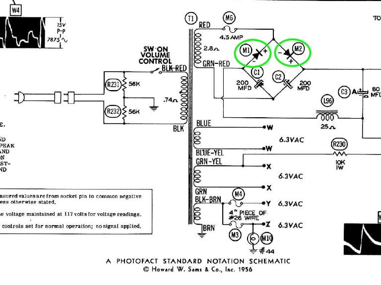
Replacing the Selenium Rectifiers
While I was at it, I decided to replace the TV's two selenium rectifiers with new silicon diodes.
Old selenium rectifiers tend to get leaky with age, and if one of them fails, it will fill the house with
a horrible stench.
The rectifiers are wired in series as shown in the following diagram:

The following photo shows what I'll use: type 1N4007 diodes and some shrink tubing.
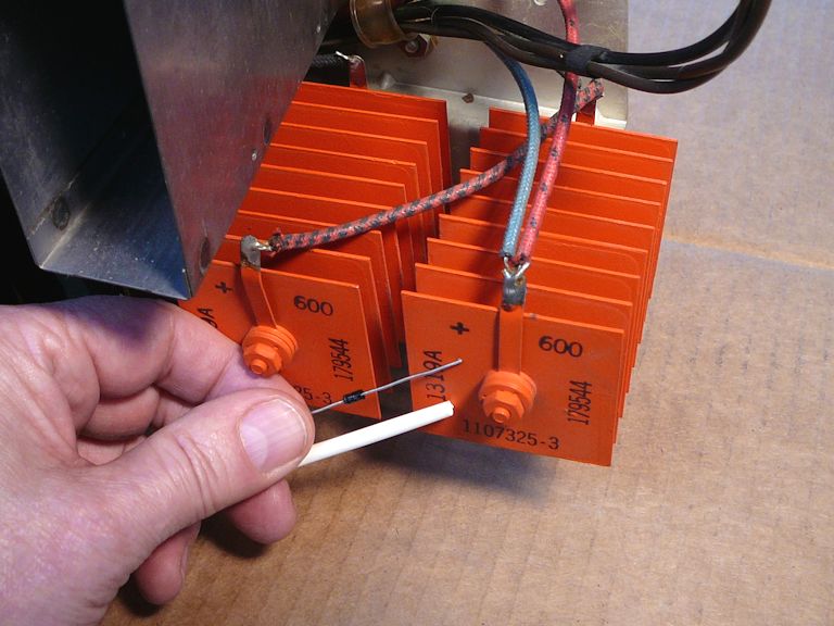
The big orange rectifiers will be left in place to preserve the original appearance. I'll
disconnect them completely, leaving the old rectifiers in place and using two of their
old connections as mounting points.

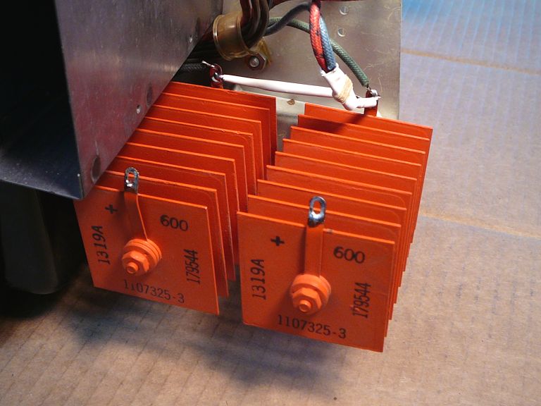
In this photo the rectifiers have been replaced:

It's not necessary to encase the whole diode in shrink tubing, but this method is
quick and it eliminates any shock hazard from their leads.
Adjusting the High Voltage
As I had guessed when I first measured the TV's high voltage at the CRT second anode, replacing
these rectifiers boosted the HV level—from 19.5 kilovolts to 24.5 kilovolts. Now I can
adjust the HV output as described in the manual:

After making these adjustments, the high voltage reached an honest 25KV and the current
draw remained at safe levels.

Now I can play the TV without worrying that I'll destroy
the flyback transformer or other important parts.
Color, Color, Where's the Color?
Now I began a long phase of investigation into the missing-color issue. I had seen
bright red, blue, and green screens during the purity setup routine,
so I knew that the CRT was good and at least some of the downstream color circuits
were operational. So, why wouldn't it display
color when I switched from test patterns to real program content?
Starting with the obvious, I re-tested all of the color tubes and re-cleaned all
of their pins as well as their sockets. I gave the same treatment to the three
video IF tubes. No improvement.
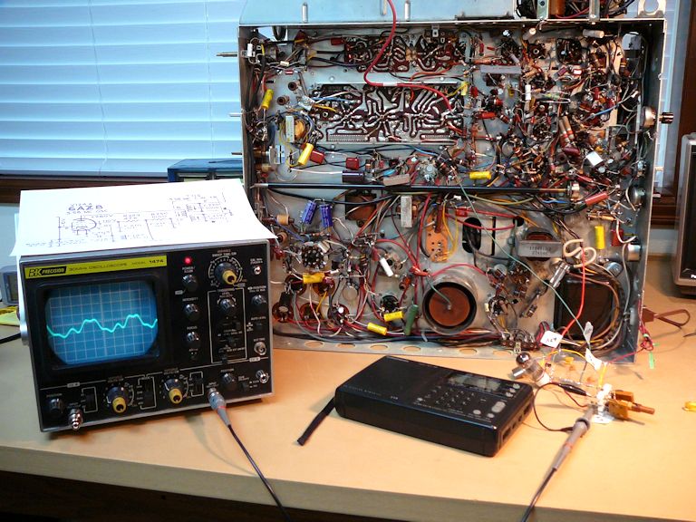
I set up my oscilloscope to view the waveform produced by the video IF section,
where the signal is handed off to the first video amplifier tube.
Curing an IF Intermittent Problem
During this process, I noticed that the third video IF tube was intermittent. Even after
repeating cleanings, it cut off the signal completely when nudged the wrong. For a while, I
thought I would need to replace that tube's socket, but I eventually cured the problem
by resoldering the socket's connections on the video PC board. While I was at it, I
resoldered all of the socket connections on both PC boards.
Loss of Horizontal Oscillation
As I proceeded with further tests, the TV suddenly lost its picture and I saw the
horizontal output tube (a 6CB5) beginning to "red-plate," meaning that its plate
element got hot enough to glow visibly. I immediately cut power, but the tube was ruined.
Runaway voltage at the HOT (horizontal output tube) is a dangerous condition; if left unchecked,
the TV might roast its irreplaceable flyback transformer. I'll have to suspend all further activity
until this problem is fixed. The 6CB5 is not a common tube, so I ordered one online.
The CTC-4 has pretty conventional circuits for producing horizontal signals. This schematic shows
the two principle tubes, a 6SN7GT for AFC and oscillation and a 6CB5 for output:

In the schematic, the waveform labeled W13 shows what to expect from the oscillator—a
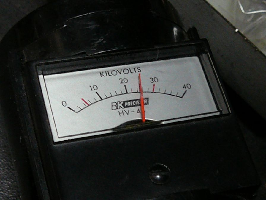
classic shape with a peak and distinctive rounded shoulders (produced by combining a sawtooth wave
and a sine wave). I had seen just such a waveform the very first time I powered up the TV:
I removed the HOT, vertical output tube, and damper tubes, in order to check some voltages. The
HOT and the oscillator were both seriously out of line, and I began to wonder if my flyback was damaged.
Videokarma member old_coot88 suggested using my B&K 1077B
TV Analyst to provide a subsitute horizontal
drive signal for diagnosis. The idea was to disconnect the oscillator's output (at C115 in the previous schematic)
and inject the Analyst's drive signal there. If things returned to normal, that would point the
finger at the oscillator, rather than components downstream from that location.
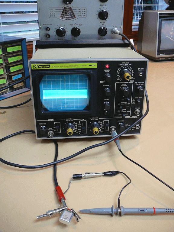
I hauled out my TV Analyst and confirmed that it produces a nice, clean horizontal signal:

I disconnected C115, replaced the tubes, and measured voltages. The worst readings were corrected,
indicating that the problem resulted because my HOT had stopped oscillating. As further confirmation,
I reconnected C115 and briefly powered the set in that condition; the HOT began to red-plate, just
as before, and I hurriedly powered down.
There aren't many components associated with the HOT, so I simply replaced the most likely suspects:
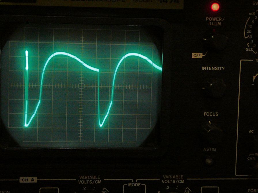
three mica capacitors and a couple of resistors. When I tried the TV again, voltages returned to normal
and its oscillator signal looked peachy:

Wahoo! Well, semi-wahoo. It's good that I fixed that potentially dangerous condition, but several
days have passed without any progress on the no-color issue. Oh, well—at least I
can resume work without burning up the flyback.
Using a CTC-11 as a Test Bed
At this point in the project, I happened to run across a beautiful CTC-11 TV at a price I couldn't
resist. Feeling that I deserved a break, I quickly restored that set, which required very little effort
to return to peak condition. (You can read all about it in my third CTC-11
article.)
It occurred to me that having a functional—in fact, beautifully functional—color TV on
the workbench might provide an opportunity. Earlier in the VideoKarma discussion, miniman82
suggested it could be educational to put the scope at various points in the color circuits
and then turn the pattern generator's color signal on and off. This might show whether a usable
color signal was getting to a particular circuit, and if so, what was being done with it.
I decided to try this trick on my CTC-11, to get an idea what to expect if I tried it on my CTC-4.
I also wanted to photograph some waveforms for future reference. Service manuals (if you are lucky)
provide some model waveforms, but not everything that you might want to see. Moreover, it's
helpful to know what a waveform looks like on my equipment, which isn't identical to what
the RCA engineers used in 1955 or 1960.
In the meantime, I had also acquired a fancier pattern generator, a Philips model PM 5518, which
had a continuously variable chroma output level, and this would be a good opportunity to use
that feature.
I spent several hours with my oscilloscope, camera, and a notepad, building up a little library of
waveforms observed on my CTC-11. For instance, here is an animated .GIF showing the results at
pin 1 of the TV's chroma bandpass amplifier when I turned the generator's chroma output to 0%, 50%,
and 100%:

As the chroma level is turned up, the waveform's amplitude bumps up nicely. Of course, the CTC-11's color
circuits aren't identical to the CTC-4's—they use incompatible demodulation methods, for one thing—but
this general technique may come in handy.
Back to the No-Color Problem
Turning back to the CTC-4, I noticed two very interesting paragraphs on page 22 of the
RCA
service clinic manual:
The chrominance channels of the receiver may be checked very effectively by simply
following the step-by-step procedure for AFC alignment, see figure 40, and noting when
and where circuits fail to respond.
The procedure serves to detect the presence and status of all signals involved in the
chrominance circuitry. It provides a quick and systematic method of tracking down any
malfunctioning circuit in the chrominance channels.
How could I not have tried this procedure before? "Yes!" I practically shouted. "Yes, I DO want to
detect the presence and status of all signals involved in the chrominance circuitry!"
The procedure requires nothing but a color bar generator and a voltmeter, and its first
steps are aimed at detecting whether the TV's 3.58-MHz color reference signal is present.
I had both of those items, and I was certainly curious about the performance of the
local color oscillator, so I plunged in. (Refer to pages 22-23 of the
manual for specifics.)
My TV flunked every test in sight. Its 3.58-MHz oscillator wasn't oscillating,
no color burst signal was passing through the burst keyer tube, and so on.
None of this came as a huge surprise, since previous tests had suggested that my video IF
section couldn't pass a usable color signal. To eliminate the video IF from the equation, I disconnected
its output from the PC board and temporarily soldered in a cable that I used to
inject a direct video signal from my color bar generator. Here's the result, an
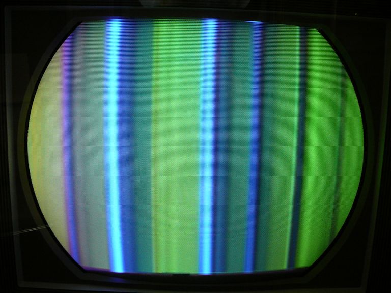
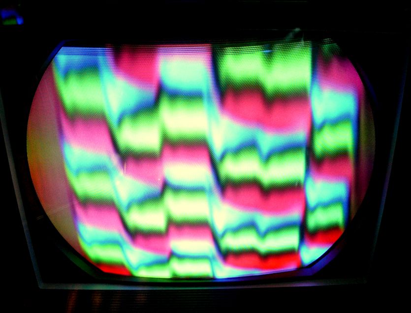
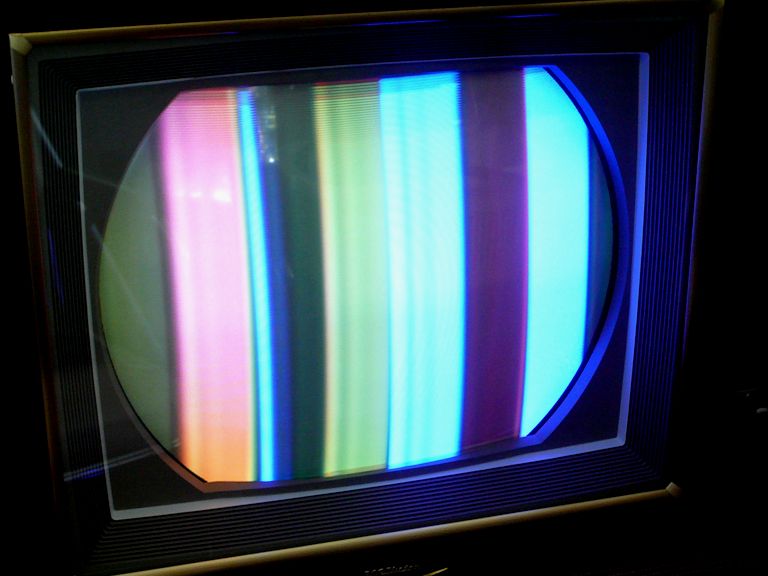
image that would become sadly familiar in the following days:

More than one VideoKarma member remarked that such colors are symptomatic of a disabled
3.58-MHz oscillator. old_coot88 suggested a rough and ready test: turning the Color
control down. If that extinguished the color bars, it meant the oscillator was not running,
or at least not running at the correct frequency. miniman82 also suggested
scoping for a signal at pin 6 (grid) of the 6AZ8 oscillator tube.
Turning down the Color control did extinguish the bar pattern completely. My scope showed
no hint of a signal at the oscillator grid, and also I measured zero volts there at pin 6, where the schematic
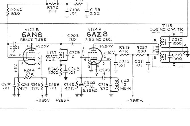
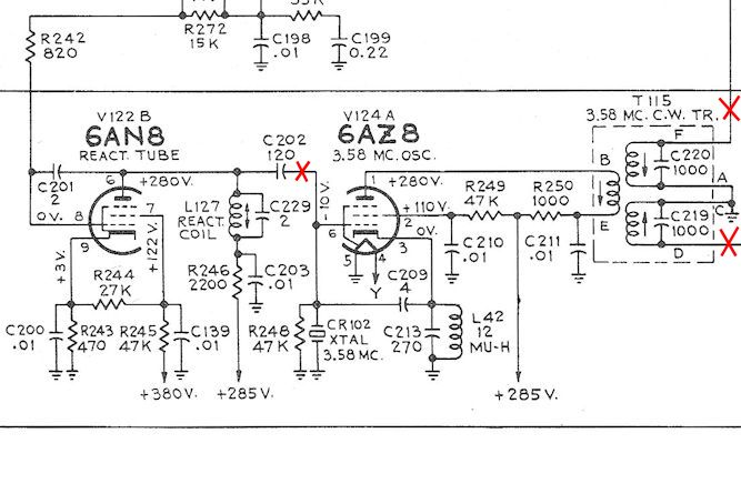
called for a bias voltage of -10 volts. This schematic shows the 3.58-MHz oscillator (V124A) along with the
reactance tube (V122B) and the 3.58-MHz CW transformer (T115):

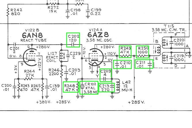
Thus began a phase of substituting and replacing components around the oscillator tube, in an effort
to get it running. I tested relevant coils for continuity, substituted three
other 3.58-MHz crystals for the original crystal, substituted other 6AZ8 tubes for the original 6AZ8,
and replaced every cap and resistor connected directly to that tube. This version of the schematic shows
the replacements:

While making those replacements, it became evident that someone had worked around the oscillator tube
before. The 120-pf capacitor on pin 6 (C202), was obviously a replacement, attached hook-and-loop style to a
wire stub left behind on the terminal. A 2.2K resistor (R246) was another hook-and-loop replacement, and the
crystal itself might also have been replaced: one of its leads was much longer than necessary, with strange
bends—not neatly dressed as you'd expect from the factory. This previous repair work might have been perfectly
competent of course, but the work suggests there was trouble at the oscillator in the past.
Injecting a 3.58-MHz Drive Signal
Around this time, forum member dtvmcdonald suggesting injecting a 3.58-MHz signal if possible, not only
to test the quadrature transformer (T115), but also to independently test the 3.58-MHz crystals that I was using.
That reminded me that I owned a Sencore VA62A Universal Video Analyzer capable of producing such a drive signal.
Here's what the signal output looked on my scope:

My scope had a little trouble locking onto that signal, but it resembled a sine wave.
Curious to see what would happen, I disconnected the tank circuit (combination of R248 and crystal CR101) from
pin 6 of the oscillator and connected the VA62A's signal in its place. This animated .GIF gives a rough idea
of what appeared on the screen:

At last, I could see something other than the same old green and blue bars! With a substitute 3.58-MHz
signal in place, the colors rolled up the screen, somewhat like the rolling colors I had seen when
battling a color sync issue in my RCA CT-100. At times I could
even see flashes or red or yellow in addition to green and blue.
We can't expect the TV to display normally with this setup, but that little experiment gave me some hope.
Trying a somewhat more useful test, I left the injected signal in place and connected my scope to the
output of the quadrature transformer T115. When I then adjusted the bottom slug of the transformer, I
found a zone where the signal definitely peaked in amplitude:

It's not a total bill of health, but the test suggested that part of T115 (the primary and one
secondary) was operational.
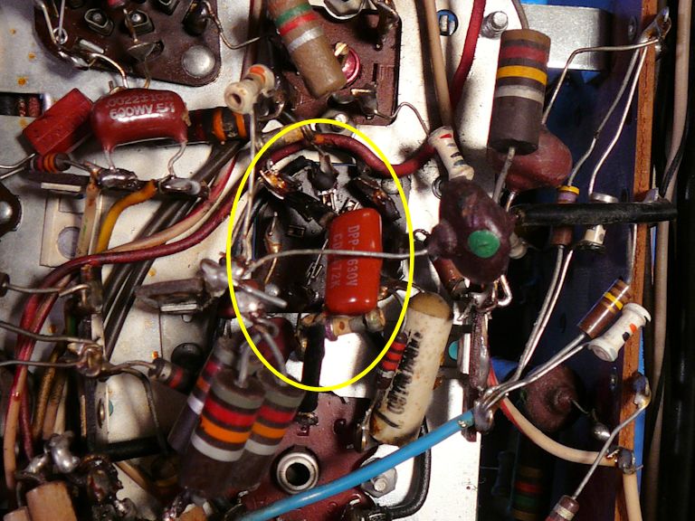
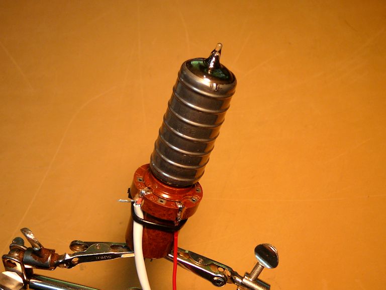
Examining the Oscillator's Tank Circuit
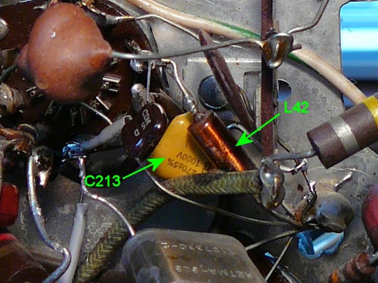
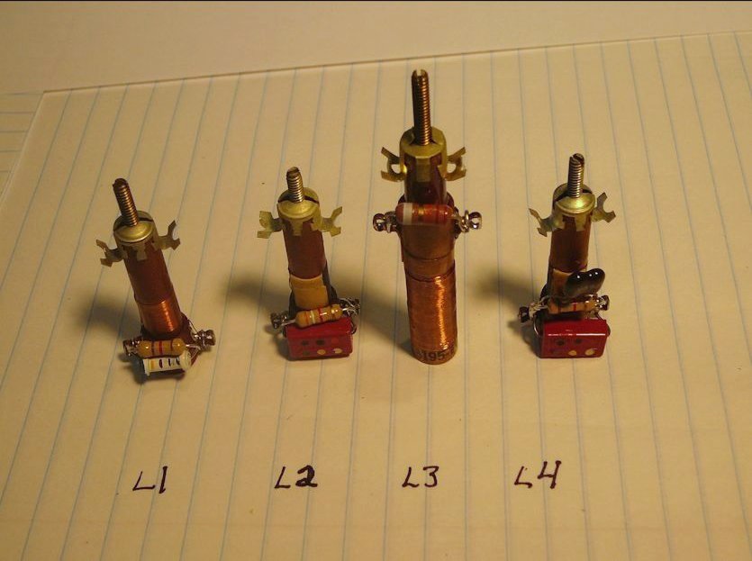
By now, I had replaced nearly everything attached to the oscillator tube—except the
inductor labeled L42, which, wired in parallel with capacitor C213, forms a tank circuit:
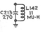
The purpose of the tank circuit is to resonate near 3.58 MHz and excite the crystal
into oscillation. Those components (C213 and L42) are tucked into a cramped area near the oscillator tube:

Notice the dark stain on the green fabric-coated wire beneath L42. When I loosened one
end and lifted up the coil, it looked like the coil had overheated and left some of its
varnish coating behind—perhaps even burning a few of its windings:

I found a couple of suitable (12-microhenry) inductors at a local surplus store and went about replacing
L42. While I had the new and old parts on the workbench, I tried a test suggested by dtvmcdonald,
sweeping the tank circuit with a signal around 3.58 MHz and watching for a peak on the oscilloscope.
The idea was to set the signal generator to about 3.58 MHz and connect the signal generator and
scope to the top of the circuit. Then I could slowly vary the generator's frequency while watching
the scope for a peak in the waveform. old_coot88 recommended adding a small cap between the
generator and the circuit. Here's the little test circuit that I temporarily soldered together:

The next image is an animated .GIF showing the result. When I swept the frequency up and down, I could
see a definite peak in amplitude.

However, the peak was not at 3.58 MHz, but significantly lower. By substituting lower-value caps
for C213, I was able to move the resonance point up to around 3.5 MHz. Who knows, possibly there
was something wrong with my test setup, or the original circuit wasn't designed to resonate at
exactly that frequency. Out of curiosity, I substituted the original coil (L42) in the test setup,
and got exactly the same results.
What was learned? Although no smoking gun was uncovered, the test answered my doubts about
the grungy-looking coil (L42). Despite its burnt appearance, it performed the same as a new one, so
perhaps it was good, after all.
Since the new inductor performed just like the old one, I concluded that it would be an acceptable substitute.
I installed the new one in the TV, along with a new 270-pf cap for C213.
Bench Testing the 3.58-MHz Crystals
At this point, I still had lingering doubts about the original 3.58-MHz crystal. Replacing it with
one of my substitutes hadn't changed anything, but I had never verified that my spares were good.
Besides the original crystal, I had three others: a new one I had purchased while working on my
CT-100, and two used ones I found in a box of spare TV parts acquired sometime in the past. It
would be nice to confirm that at least one of them is usable!
Following another suggestion from dtvmcdonald, I connected a 10K resistor across the crystal's leads
and slowly swept the signal generator's frequency above and below
3.58 MHz. The oscilloscope showed a definite peak in amplitude around the target frequency:
I tested the others in like fashion, with the same results. My conclusion was that they were all good—or, at
least they all performed the same way in a simple bench test.
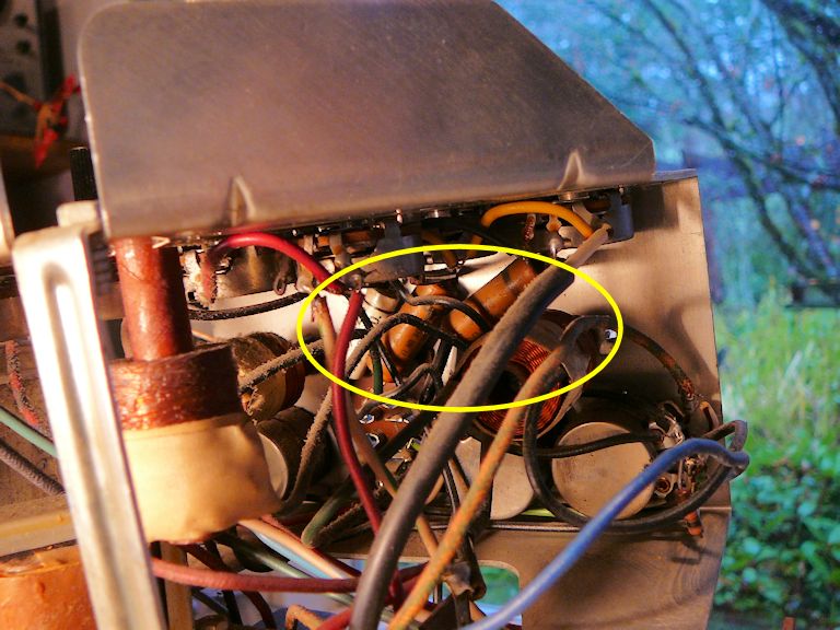
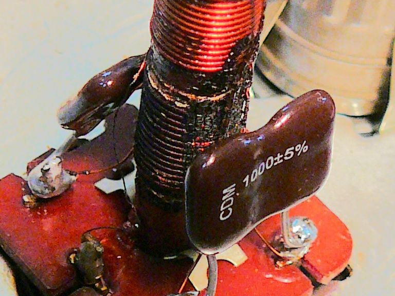
A Look inside the Quadrature Transformer
In the interest of leaving no stone unturned, I removed the cover of the quadrature transformer
(T115) to test the two little capacitors wired in parallel with the secondary coils.
The RCA schematic labels them C219 and C220:
The lower coil of T115 looks black and crusty, as if it has overheated. This photo was taken after
I replaced the two 1000-pf mica caps on the base:

Replacing those two caps didn't cure anything, but at least I could eliminate them as
culprits. But now I have to wonder whether this transformer is functional. Is the damage merely
cosmetic or does one of the coils have shorted turns?
Despite the burned appearance, all of the hair-thin transformer leads are still intact, and
the coil resistances match the values given in the Sams manual. The schematic gives a resistance
of 6.8 ohms for the primary, and the parts list specifies .2 ohms for each secondary.
Who knows, perhaps the transformer is good, but in case it's damaged, I contacted a couple of
suppliers. I was not optimistic about finding a replacement. The CTC-4 was manufactured for a
very short time and transformers like this are not necessarily interchangeable.
To my surprise, Play Things of Past had a
replacement—not for the original RCA part number (100430), but for the Meissner
equivalent (17-6014) that was listed in the Sams manual. I later learned from
Moyer
that a Miller 6025 is also equivalent.
A New Quadrature Transformer
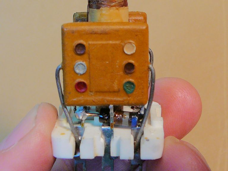
A few days later, my new transformer arrived. Here it is, pictured next to the can
that I removed from the old T115:

Inside the box was a tightly folded data sheet, browned from oxidation, which fell into pieces
when I unfolded it. After gluing the pieces onto a bigger sheet, I learned that this
transformer is not identical to the one used in my CTC-4. It has a resistor in parallel with
each little capacitor and the example circuit is also different:
As in the CTC-4, this circuit has a chroma reference control (reactance) tube and a chroma reference
oscillator tube, but it has an extra amplifier tube between the oscillator and the quadrature transformer.
This makes me wonder whether the transformer expects a higher signal level than my TV can deliver.
Perhaps it's a "plug-n-play" replacement for my
transformer, but chroma oscillator circuits are finicky.
When I removed the new transformer's case, I found construction differences from the
CTC-4 transformer. This one has 680-ohm resistors in parallel with the caps and
its capacitance values are 1500 pf rather than 1000 pf:

In the coding scheme used on this cap, you read the dots clockwise, starting with the white
dot (upper right) that indicates it's a mica type. The next three dots
(brown-green-red) give a capacitance of 1500 pf, and the silver dot indicates 10% tolerance.
After some research, I determined that the Meissner example circuit comes from the RCA
CTC-2B television, the preceding model which differs from my CTC-4 in various ways. Further research
showed that the same transformer was used in the CT-100, RCA's original color TV.
The CT-100 did not use an extra amplifier tube between the oscillator and quadrature transformer, a fact that
suggests that this transformer might work in the CTC-4 after all.
To complicate the picture, all three of these TVs use different circuits in the
color demodulators, which receive the two outputs from the quadrature transformer.
The CT-100 uses I/Q demodulation, which you can read about in
my article about CT-100 design.
The CTC-2B uses a method called Q/R-Y, and the CTC-4 uses the R-Y/G-Y method,
a unique scheme that was superseded in later color sets.
Although it just came out of the box, this is a 60-year old part and I don't want to take
chances. I unsoldered one lead and tested the cap for leakage on my
EICO 950B cap tester. The capacitor passed with flying colors, showing no leakage at 450 volts.


It's tempting to pop in the new transformer in place of the old one, but the installation
site is crowded—difficult to photograph, much less reach with tools:

You can't see them all in the photo, but removing this transformer means disconnecting ten
leads from six terminals. Before I undertake this surgery, it would be nice to know if
this part will replace the CTC-4 part without having to modify either the transformer or my television.
Testing the New Transformer and the Oscillator
At this point, forum member oldcoot_88 suggested another test:
Phil, there's something I was gonna suggest earlier to see if the osc can be
coaxed to run, but thought the better of it until seeing the CTC-2 schematic.
The CTC-2 has the osc plate clamped hard with a .01 cap. Try disconnecting the
CW xfmr's primary completely, and shunt directly across where the primary was.
Bypass cap C211 is now clamped directly to the plate. This duplicates how the
CTC-2 osc plate is wired. Bring the scope probe next to L42 to see if the osc
is running.
Again, for reference here's the schematic. The idea was to disconnect terminals B and E
of the transformer, and then connect the junction of C211/R250 to pin 1 of the oscillator tube.
Finding the correct signal at inductor L42 would indicate that the oscillator was running.
When I tried this, a clean signal appeared at L42:

What's more, when I connected the new transformer's primary coil temporarily in place of
the old one, the signal remained stable. The trace shown in this photo shows that the oscillator
is running close to 3.58 MHz:

As a further check, I brought out my digital shortwave radio (a Grundig Yachtboy 400) and
held the antenna near L42. I tuned for a few moments and found a discernible signal at 3580 kilohertz,
near our target frequency.
These were encouraging signs. The oscillator was running at about the right frequency
and connecting the primary coil of the new transformer didn't kill the oscillation.
A Burst of Color!
I went on to make further tests, which involved disconnecting and then reconnecting the
inputs to the reactance tube (V122B) and the oscillator tube (V124A). To my surprise, when
I reconnected everything in preparation for yet another test, rolling color bars suddenly appeared:

The color sync is off base, but this was more color—moving color—than I had
seen before, and I was able to slow the rolling and make the colors hover in place by adjusting
the reactance coil (L127).
I had seen similar rolling colors before, but only when injecting a 3.58-MHz signal from a
test instrument, not when relying on the TV's native 3.58-MHz signal.
The First True Color Bars
The next day I launched a systematic resistor hunt through the chrominance section of the television, beginning
where the video signal was picked up from the video IF section and moving down the color
signal chain. I replaced a number of out-of-spec resistors, including a couple whose values were
off by about 100% (the normal tolerance for resistors is 20% at most).
About midway through this process, I decided to retry the TV
as a sanity check. When replacing a bunch of components, I like to play the set from time to time,
to make sure that I haven't made anything worse through a wiring mistake.
Here's what I saw after making a few adjustments:

Wahoo! These are genuine color bars, a dramatic change from the "colorless bars" that I saw
earlier. Something must be working right!
Before you get too excited, note that we
do not have colors in the right order. The following photo, taken years ago in one of my
CTC-11
projects, shows the standard NTSC sequence of white-yellow-cyan-green-magenta-red-blue-black:

Putting the right colors in the right place is critically important.
To demonstrate the point, here's an animated .GIF image from the TV at this
stage of the project. It shows the Witch reaching for Dorothy's ruby slippers:

Pretty ghastly, but even wrong colors are better than none at all. Perhaps things will
improve as I continue the resistor hunt and weed out more bad ones.
Seeing color bars felt like a breakthrough, but my joy was short-lived. The TV's color sync was
extremely twitchy, apt to lapse into rolling bars unpredictably.
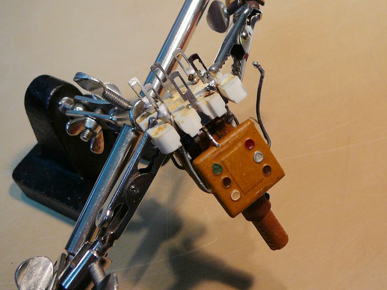
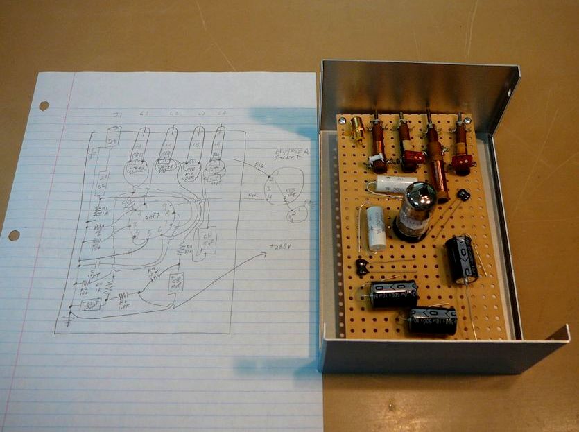
Building a Model Oscillator Circuit
I had a new quadrature transformer on hand, and I had gotten some encouraging test
results from it, but I wasn't convinced that I could simply install it and expect
it to work. Videokarma member jr_tech suggested building a "breadboard"
oscillator circuit with the new transformer and testing it on the workbench.
I happened to have all of the needed parts on hand:

The completed circuit doesn't look beautiful, but it's only a temporary test bed
for the transformer.
Powering it seemed problematical until I realized
that I could tap the CTC-4 for the needed filament and B+ voltages.

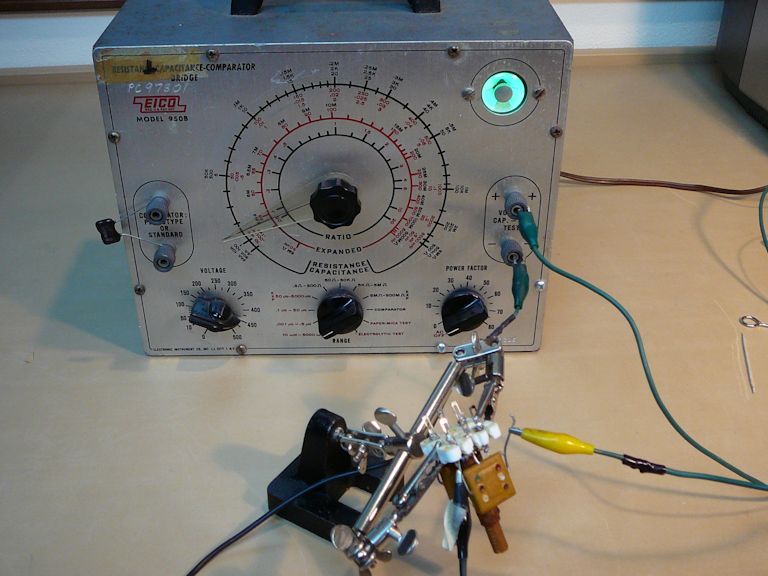
Preliminary tests
were encouraging. In the next photo the circuit is wired up to
the CTC-4 chassis and I am checking its output using the oscilloscope
and the digital shortwave radio. The scope displays the output from Terminal F of the new transformer:

Here's the waveform from the other T115 output, terminal A:

The radio told me that the oscillator was running near
the target frequency of 3.58 MHz, and the scope traces were
similar to what I had previously observed from the original transformer when I disconnected its
output terminals: one signal was a clean sine wave and the other was somewhat irregular.
Observing Phasing in the 3.58-MHz Transformer
So far, I had seen similar waveforms from both oscillator circuits (the original and the breadboard), but
color demodulation demands more than the right wave shapes. The two signals produced by the
3.58-MHz transformer need to be in the proper phase relationship.
I had learned in my CT-100 project that its 3.58-MHz transformer produces
signals that are 90 degrees out of phase—"in quadrature"—and
that the demodulation section of the TV depends on this precise relationship. You
can read more about that demodulation method in my CT-100 electronic design
article.
My oscilloscope has two channels (A and B), so it's possible to view both waveforms at once
and judge their phasing. I was curious whether my breadboard circuit, with its
CT-100-compatible transformer, could produce two signals with that phasing.
After a few minutes of experimentation, I succeeded.
A more interesting question was whether I could get the same results from my TV's original transformer.
I had seen each secondary coil produce some kind of signal, but that
told me nothing about phasing, and I still wondered if the burned-looking transformer had
been damaged.
It took only a few minutes to disconnect the breadboard circuit and restore connections
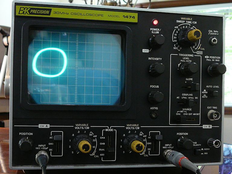
to the original transformer. The next photos show the transformer's two outputs adjusted to
approximately 90 degrees. In the second photo, I switched the scope's time base to channel
B, resulting in an approximate circle, as shown in my scope manual.


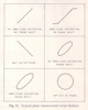
This was encouraging. Perhaps the old transformer is still operational, despite its appearance.
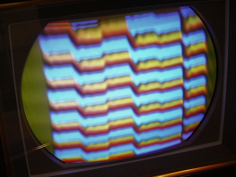
Adjusting the Oscillator Frequency
I had done that little experiment without looking at the screen. When I took a peek, I saw
the dreaded rolling horizontal bands instead of stable color bars.

Videokarma member old_coot88 remarked that the oscillator was running off frequency,
and he suggested connecting a capacitor in parallel with the 270-pf cap in the tank circuit
to bring the frequency down.
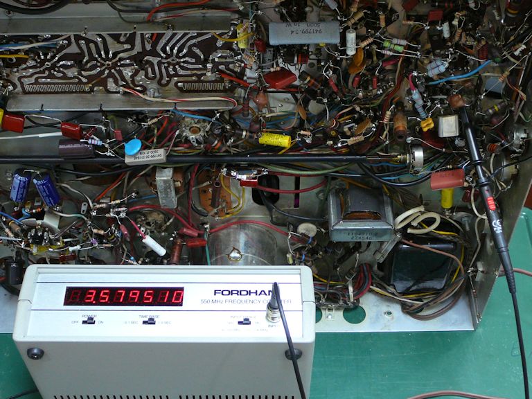
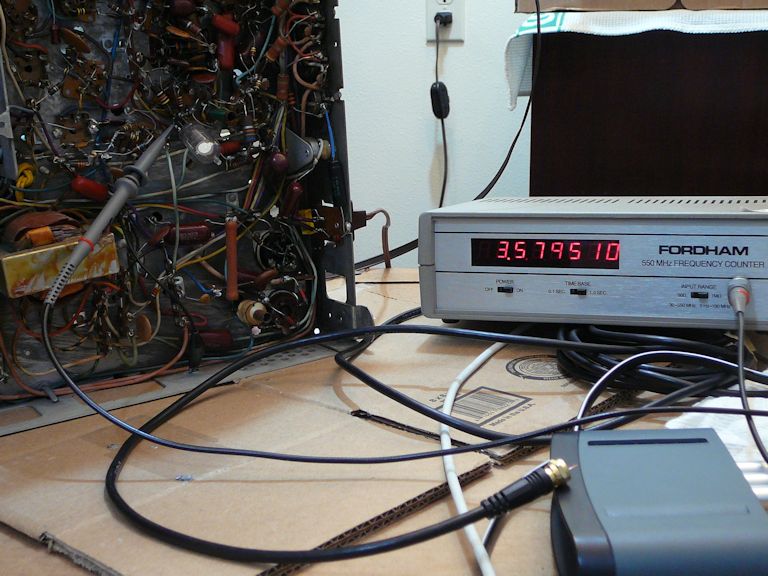
It was frustrating not to know the oscillator's actual frequency; my digital radio could only give
a vague indication of frequency. On craigslist, I found a frequency counter for $20 and drove to pick
it up the same day. When I tried it out, old_coot88's prediction was confirmed: the
oscillator was running too fast. I tried adjusting it the kosher way, using the reactance coil,
but the lowest I could bring it was 3.579629 MHz, quite a bit above the ideal frequency of 3.579545:

I experimented with caps of different values, and found that a 100-pf cap brought the frequency very close:

When I tacked the 100-pf cap into the oscillator circuit, the oscillator stabilized and I had
color bars again:

Yah, they're still rotten colors, but the oscillator is running and the color system can lock again.
I'm thankful for small mercies.
Connecting the Model Circuit
The next logical step was to connect the model oscillator in place of the
old one. To do this, I needed to disconnect the original circuit at three places,
shown in this schematic:

In plain English, I'll need to disconnect the input at the oscillator tube's grid and disconnect the
output of the secondary coils at terminals A and F. Then I'll need to connect the breadboard circuit
with three additional wires to those points in the chassis.
The next photo shows the breadboard circuit lashed up in place of the
original oscillator circuit:
Plugging in the breadboard circuit had inconclusive results. The color lock operated with difficulty
and the hues in color bars were wrong—not dramatically better than when the native circuit
was connected.
Some of the twitchiness might result from hanging long uninsulated leads
halfway down the chassis. The oscillator circuit is very sensitive in the best circumstances.
You can alter the oscillator frequency simply by touching a finger to the crystal or to a
capacitor in the circuit. At one step in the service manual alignment procedure, you are
instructed to temporarily disable the oscillator by clipping a foot-long length of wire
to pin 6 of the oscillator tube (where one leg of the crystal is connected).
The experiment suggested that the new quadrature transformer might
work as a replacement, but it wasn't a sure thing.
Observing "3.58-MHz" Frequencies in Output Devices
It was interesting to carry my new frequency counter around the workshop and compare
frequency readings between my CTC-4 and CTC-11 (which has great color), when
using different input sources. It became clear that the oscillator in each TV
was successfully locking onto the slightly different "3.58-MHz" frequencies coming in from the different devices.
In a perfect world, every TV station and video output device would hold its color subcarrier signal to
the precise frequency mandated by the NTSC, but in the practical world, some leeway must
be allowed. That reality is at the heart of a color TV's AFC (automatic frequency control)
system.
In the 1953 technical specification for color
broadcasting, the NTSC specified the color subcarrier frequency as:
3.579545 megacycles ± 0.0003 per cent with a maximum rate of change not to exceed 1/10 cycle per second per second
That's a tight standard! As I soon observed, NTSC video devices produce a signal that's in the
right neighborhood. It's the TV's job to detect that pretty-close signal and lock onto it.
For instance, in these photos, my two TVs have locked onto 3.579510 MHz, the
frequency output by the Blonder-Tongue agile modulator that I use as my
in-house TV transmitter.


Through similar comparisons, I was able to deduce the frequencies output by some of my other
devices:
- Phillips pattern generator: 3.579533
- RCA DVD player: 3.579550
- Leader pattern generator: 3.579679
Lest we accuse those manufacturers of sloppy engineering, note that the counter is measuring
these frequencies out to six decimal places—in the millionths. It's a tribute to
RCA's 1950s engineering that the CTC-4 is able to react to signals and maintain stability within such a narrow range.
Installing the Replacement Quadrature Transformer
The new quadrature transformer was still an unknown quantity. It had some differences from the
old transformer and I couldn't tell from the breadboard circuit whether those differences were critical.
I decided to take out the old transformer and install the new one in the CTC-4 chassis.
Here are the two transformers side by side:

The new transformer's secondary coils are wound with finer wire, spaced more closely than in the old one.
The new unit also has capacitors of slightly different values (1500 pf versus 1200 pf), with a
680-ohm resistor in parallel with each secondary coil.
Mounting the new transformer physically was no problem, but I had to reroute a couple of connections to
accommodate slightly different terminal assignments (A-B-C, etc.). Here's the new transformer in place:

Unfortunately, the new transformer didn't work correctly. After installing it, I worked through the color AFC alignment
procedure and tried other adjustments without getting a reasonable color picture. One of the waveforms output by
the transformer was very irregular and the two signals were badly mismatched in amplitude. Keep in mind that in
the CT-100 and CTC-2B, this transformer is fed by an additional amplifier; perhaps this TV simply can't deliver
the input signal that the transformer needs.
After some further testing, I gave up on the new transformer. I removed it and reinstalled the old one.
Replacing the Video Detector Diode
In an effort to isolate the TV's problems, I spent some time injecting a video signal and observing
the results. The idea was to bypass the TV's tuner and IF amplifier sections and replace
their output with a clean signal of known quality. This effort was inconclusive, but in the course of it,
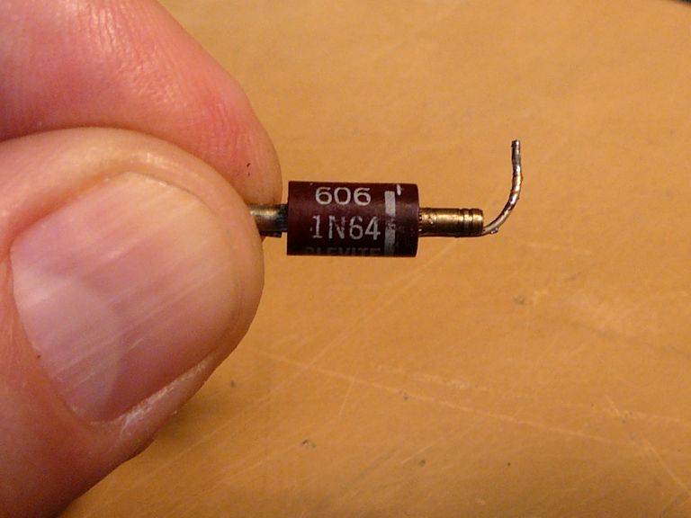
old_coot88 asked whether I had ever tested the TV's video detector diode.
That hadn't occurred to me, since the diode seemed to be passing a signal, and I tend to think of diodes as
go/no-go devices. That is, they either work or they don't. In the course of signal injection, I had unsoldered
one end of the diode, so when that experiment was done, I simply removed it and replaced it with what I had
on hand (a type 1N34). When I checked the old diode, it tested as defective, and it was a replacement, type 1N64,
where the schematic calls for a 1N60:

When I tried the TV again, I was pleased to see a true color picture. I guess the diode mattered, after all.

Now, I could see that the picture's vertical linearity was imperfect: the bottom was vertically squashed,
while the top half was stretched. The next day, I replaced some resistors
in the vertical circuits, which corrected the linearity. After repeating the color AFC alignment procedure,
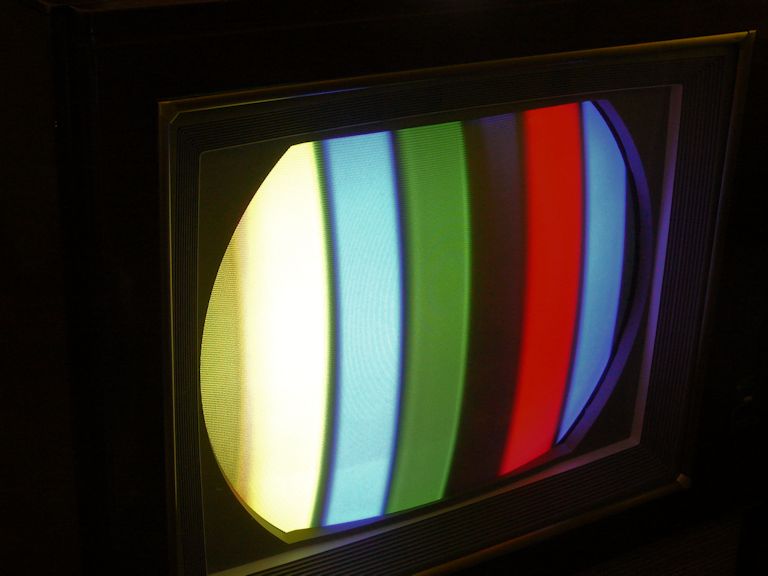
I was treated to some improved color bars:

This display wasn't perfect, but we did have the correct color sequence
of yellow-cyan-green-magenta-red-blue-black. (My camera exaggerated the contrast: the white-looking bar
was actually quite yellow and the magenta bar was not that dark.)
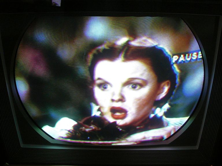
At this stage, real program content looked pretty respectable. Here's a paused frame from a DVD:

Although that picture looked encouraging, the TV still had problems. The vertical hold was
unstable, and on some signals the entire picture began to jitter vertically. The color lock was weak and
it tended to dissolve into rolling color bars unless the fine tuning was very carefully adjusted.
Switching to a different program source, or simply changing channels, required a
twitchy retuning.
The color demodulator section also needed work. Although I was able to adjust the Hue
control for reasonably close colors on a test pattern, that setting was completely inappropriate
when I switched to real programming. Sometimes I could adjust the hues for a normal picture,
and sometimes not.
The TV also seemed to need a full alignment. When I moved
the fine tuner, it showed a great black and white picture through the middle of the tuning
range, with color appearing only at the extremes of the range. This suggested that the chrominance
portion of the signal—compressed and more tightly coded than the basic luminance data—just
couldn't get through the tuner and IF stages.
It's the garbage-in/garbage-out principle.
Even if the chrominance circuits are working perfectly, they can't make a great color picture
if the incoming signal is weak or corrupted.
I don't have the equipment or expertise to do that alignment, so I decided to take another
look at injecting the video signal. This would bypass the IF section and eliminate any
problems from misalignment.
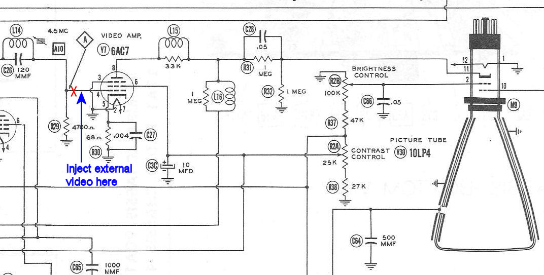
Design Requirements for Video Injection
At various points in this project, I had tried injecting a video signal from my pattern generator
at the TV's first video amplifier tube (or thereabouts), in an effort to remove the tuner and IF stages
from the equation.
In a simpler TV, like my black and white Admiral 24C15,
injection works like a charm. You immediately get a crisp, clear picture with wonderful contrast.
The simpler Admiral TV has a single entry point for the video, at the grid of its video amplifier tube (V7):
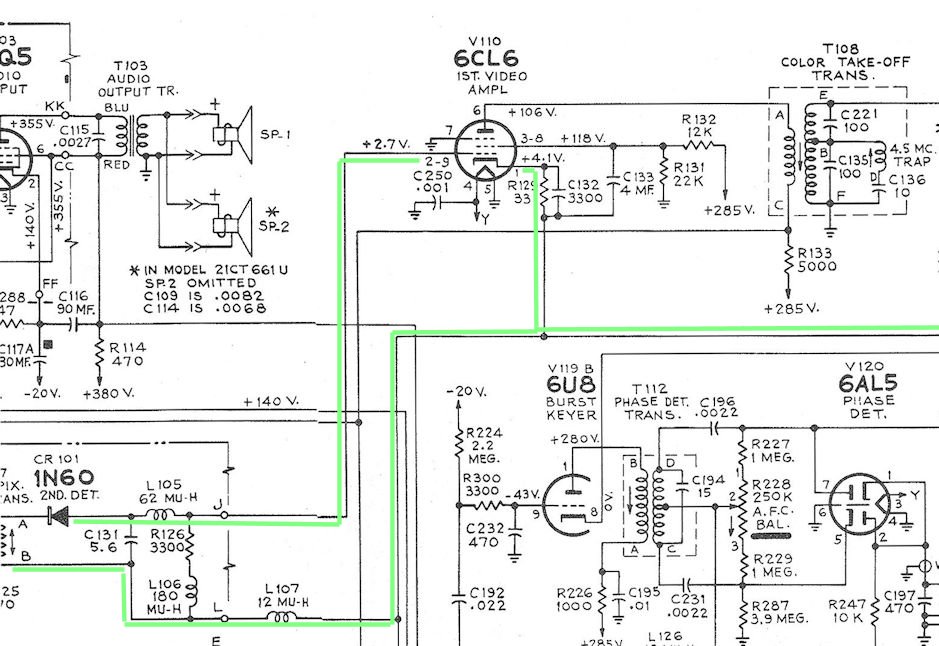
Injection is less straightforward in my CTC-4, which has multiple paths from the output of the
IF section to its first video amp tube (V110):

As the second schematic shows, there are connections to the video amp's cathode as well as its grid.
When I scoped the cathode and grid using a color bar pattern, I found that the signal delivered by the IF stage to the grid
(pin 2) of looked more like a black and white (luma-only) stairstep than a full color signal.

(In these photos, the scope is displaying the TV's signal at the top. The bottom trace shows
the signal coming directly from the pattern generator.)
The signal at the cathode (pin 4) of the video amp looked more like what I had expected.
In the next photo, the bar shapes are fuller, not attenuated, and the color burst signal is clearly present, although somewhat distorted.

What's going on here? The RCA service manual has this to say:
There are two stages of luminance signal (brightness) amplification in the 21CT660 series
receivers. The first video amplifier uses a type 6CL6 tube. It supplies from its plate circuit:
color signal information (which is removed through the color take-off transformer, T-108, and
fed to the bandpass amplifier), sync, AGC and Sound information for their respective circuits. The
drive for the second video amplifier stage is obtained from the cathode circuit of the 1st
video amplifier.
That explained why I had observed different signals at the grid and the cathode, but it
didn't tell me exactly how to inject video on this TV. I had already tried injecting
a plain vanilla video signal at those points (and several others), with disappointing results.
Clearly, the CTC-4's video amp expected something different for input . . . but what?
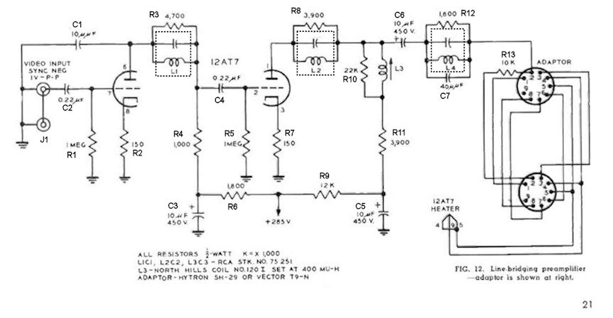
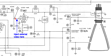
Video Preamplifier to the Rescue
At this point, Pete Deksnis of the Videokarma forum mentioned that
the June, 1956 issue of RCA Broadcast News included an article describing a CTC-4 video
preamp. This is the same article whose plans Pete had refined (and I followed) to build
an RCA CT-100 video preamp:
The article was written for engineers who wanted to use an RCA CT-100, 21CT-155, or CTC-4 TV as
a color broadcast monitor in a television studio. It presented two alternate plans for the CTC-4 and Pete recommended the second,
which uses a standard video input. You'll find that plan on the last page of the article; here is
the schematic diagram:

The article also clarified what sort of signal is needed for injection. The TV's IF output has a
20-db amplitude roll-off in a certain frequency range, and the TV's video amp has a 20-db rising
characteristic to complement that roll-off. (In other words, the IF output is different than a
standard video signal.) To substitute for the IF output and inject video directly,
RCA designed a video preamp whose output mimics the signal produced by the TV's IF section:

The preamp takes a standard video signal as input and gives it the characteristics needed
by the CTC-4. That's exactly what I need.
Building a Video Preamp
I began by labeling the components in the preamp schematic (R1, R2, etc.) and sketching a possible
layout for the device:
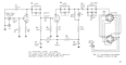
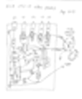
The preamp uses a 12AT7 tube, along with four adjustable coils (L1, L2, L3, L4) and sundry capacitors and resistors.
A VideoKarma forum member helped me by cross-referencing the old RCA part numbers
for the coils. I ordered three Merit TV-151 4.5-MHz sound traps and a Miller 6195 adjustable coil
from Play Things of Past.
(The rightmost coil in the photo is an alternative to the Miller 6195 that I didn't use.)

Out of curiosity, I put one of the coils on a scope with a 4.5-MHz signal and I was able to peak the
signal's amplitude by turning the adjuster, just as you'd expect.
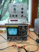
The schematic calls for a resistor in parallel with each coil. It's convenient to mount those
resistors right on the coils:

I'll build the preamp on a piece of perf board mounted on a small metal sub-chassis. I gathered
parts and tried laying them out:


Using half of a metal project box gives me a sub-chassis that fits neatly into the
space near the TV's video amp tube:


The preamp design requires an adapter, into which the 6CL6 video amp tube will be plugged.
The completed adaptor will look something like the second photo.


I was able to locate an adapter with the original part number, a Vector T-9N. This widget can act
as a tube extender, letting you test tube voltages without going under the chassis. But it can also be
disassembled to access the long pins inside, letting you make circuit changes or connections on a tube
without disturbing its factory wiring:


Referring back to the schematic, I'll need to add a 10K resistor on pin 2 of the adaptor and
make a connection from the preamp's output to the same pin 2:
I soldered a 10K resistor around the adaptor's pin 2 extension, clipped the pin between the resistor
leads, and reinforced the gap with non-conductive adhesive so the pin won't wiggle and miss its hole
when reassembling the adaptor:


The schematic requires no connection for pin 9 on the adaptor. I trimmed the end of the pin 9 extender so that
it doesn't protrude from the adaptor's male end:


I'll need connections to power the 12AT7 tube and bring the preamp's output into the adaptor (and thus
into the 6CL6 video amp tube). I formed slots with a Dremel tool below pin 2 and 4, soldered the signal
cable to pin 2 and a filament lead to pin 4, and secured both wires with a snap tie:


I'm wiring the board so that the coil adjusters can protrude through the top of the sub-chassis.
If I drill mounting holes of the right diameter, their tops will snap into place, just as in the TV's
native transformer cases:
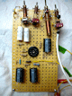

Here's a view of the completed preamp with 12AT7 tube in place:

In the next photo, the video input jack is at the top left, with four
coil adjusters to its right. The adaptor requires no permanent modifications to the TV, so it has
clip leads to connect to ground and to the 285-volt B+ power source:

Below and to the right is the preamp's adaptor, which plugs into the socket of the 6CL6 video
amp tube. It has a red lead to bring filament power to the preamp's 12AT7 tube and a white lead
to send the preamp output to the TV.
Sadly, the preamp didn't work well, even after I noticed and fixed a small wiring error.
At this point, a rational approach would be to bench-test the preamp separately
from the TV, feeding it a video signal and viewing its output on an oscilloscope,
but that would require a stand-alone power supply, to provide 285 DC volts (for B+)
and 6.3 AC volts (for the 12AT7 filament), and I don't have such a supply.
By this time, I was weary of working (and working, and working) on this CTC-4,
so I set it aside and turned to other projects for the time being.
Stay tuned . . .
|