RCA Model CT-100 Color Television (1954)


The RCA CT-100 is a Holy Grail for TV collectors. Introduced in 1954,
it was the first color television sold in significant numbers, helping to
launch a revolution in TV broadcasting. Very few CT-100s were sold during its short
production run and only two to three dozen working examples can be found
in the world today.
Meet the RCA CT-100 Color Television
The early 1950s were an exciting time in television. In 1946, RCA had scored an
early success with its Model 630TS and
established itself as an industry leader. During the next few years, customers
lined up to buy TVs and manufacturers offered newer sets with bigger
screens, lower prices, and better performance.
Television companies raced to supply this booming market with color and in
1954 that dream became reality. Although Westinghouse beat them to market by
a few weeks, RCA's CT-100 was the world's first color TV produced in meaningful
numbers.
With a 15-inch color picture tube, the CT-100 had a regal list price of $1000. For
comparison, the base price for a new 1954 Chevrolet Bel-Air automobile was $1095.
Here is my CT-100 partway through restoration, before
the cabinet had been refinished.
Color television was a huge novelty in 1954. Owners of CT-100s often invited friends
and neighbors to goggle at this new invention. For many people, the CT-100 offered
their very first color TV experience, even if it was only to peek at
a demo in a dealer's showroom.
RCA built approximately 4,400 CT-100s. There are only about 160 known survivors, and
of those, for reasons we'll explore later, only a handful of sets actually work.
Some CT-100 owners call themselves "custodians," underlining
the importance of preserving these rare TVs. I certainly feel lucky to have one.
The CT-100 was advertised by many local department stores around the country, but
as far as I know, RCA published only one national ad for the set. This advertisement ran in
the Seattle Times on Sunday, August 15, 1954:
Expensive and cantankerous, the CT-100 was soon superseded by TVs with
bigger screens and improved electronics. RCA's second color television
came in 1955, model 21-CT-55 with a 21-inch screen.
Still, the CT-100 marked an unforgettable "first." There are
other working examples in addition to mine, but the only ones that I've seen personally
are in museums, in Washington and Ohio.
CT-100 Electronic Design
There's much to be said about the electronics of the CT-100, so much
that I put it in a separate article,
RCA CT-100 Color Television Design.
That piece covers design highlights; discusses CT-100 color demodulation
and the NTSC color standard; and provides a library of reference
material including a complete RCA service manual and the
NTSC specification.
Here are the operating instructions from the CT-100 Owner Manual.
These pages describe the user controls and the correct sequence of operation.


This diagram identifies more of the CT-100's controls:
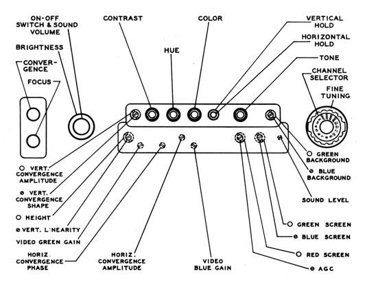
A number of these controls are reserved to the serviceman.
The upper row of controls is behind the hinged pencil box cover.
Those in the lower row are accessed by removing the pencil box cover and wooden panel.
The Focus and Convergence controls are in a small recess in the cabinet's side.
The next diagram gives a birds-eye view of the chassis and
identifies all of the tubes and controls, including some service adjusters not
shown in the previous diagram.
We'll refer to both of these diagrams later.
Note: CT-100 schematics were published by Sams and by RCA. In this article, I'll
refer to parts by their Sams numbers, since those are widely known and
both Len and I used them in our restoration notes and charts.
CT-100 Restoration
This rest of this article relates some highlights of my experience with a
CT-100. I was aided along the way by fellow collectors Pete Deksnis and
John Folsom, two gurus of CT-100 restoration.
Finding an RCA CT-100
In May, 2009, I was contacted by a collector named Len Dole, who owned a CT-100. He had
begun restoring it, but health issues prevented him from finishing the
project and he wanted to pass it on to someone who would complete the
work. He sent these photos:
We struck a deal and, with my son Peter, I flew to California and
rented a moving van to bring the television back to Washington state.
In addition to the TV chassis and cabinet, we packed up two 15GP22
picture tubes, an oscilloscope and
other test equipment, and several boxes of CT-100 parts and
electronic components. In the third photo, after two very long days
of driving, I have unloaded
enough stuff to uncover the real goodies in the back.


Taking Inventory
Len had gotten this CT-100 from a neighbor, the original owner.
Len had never tackled a TV, but he was an engineer
and had restored several old radios. He began a total
restoration, recognizing that it would be a major project.
Len made a lot of progress and exchanged email with Pete and John several
times. He replaced all of the original paper and electrolytic
capacitors and many resistors that were out of tolerance. He found replacements
for a couple of other components: a new vertical dynamic convergence transformer
purchased from John and a horizontal centering control donated by Pete.
My first task after unpacking was to inventory what I had.
It looked daunting at first.
In addition to the chassis, cabinet, and
two picture tubes, there were several boxes of parts, new and old,
and assorted restoration supplies.
Some things were obvious, others were not. I found two hinged
"pencil box" covers for the front panel controls. One of
them presumably belonged this cabinet.
I found a box of knobs, some broken, others intact, and a few that
looked like they belonged to other devices.
Len also left four notebooks with printouts of CT-100 articles,
annotated copies of the schematic, and charts showing measurements of
resistance and voltage. I'm sure it all made sense to him, but flipping
through them, I couldn't tell exactly where he left off.
Lots of work had been done, but how much remained?
CT-100 Provenance
Three days after we arrived home with the TV,
Len passed away. This meant, sadly, that he wouldn't be around to
see his project completed. It also left me on my own.
Here is what Len's widow told me about the TV's history.
The CT-100 was bought new by a local man who was an engineer at the original business here.
Many of the old-timers who are still around remember going to his house to watch it with him.
It was their only TV for many years until they eventually replaced it (I don't know when).
Being an electronics engineer, he kept it in his garage, along with the spare tube that he
had acquired along the way. After his wife died, he was cleaning the garage and decided
to give it to Leonard, because of his interest in old radios. We moved here in October 2003
and the TV joined us shortly thereafter, and Leonard had a new hobby.
It's fun to know where the television came from. The original owner kept it for fifty years,
and Len had it for six, working sporadically on restoration during that time.
As third owner, my mission is to restore it to original working condition and preserve
it in that state.
Serial, Model, and Chassis Numbers
My CT-100 has chassis serial number B8003603 and cabinet serial number
429. The chassis number is stamped below the flat resistor on the
back panel.

CT-100 chassis serial numbers are believed to begin at B8000100. The earliest
known number is B8000158 and the newest is B8004019. With chassis
B8003603, my set falls near the end of the production run, among
the newest dozen CT-100s that have been identified.
The CT in RCA model numbers and chassis numbers means Color Television.
CT-100s have chassis type CTC-2 and you can see that number
stamped in black ink on the rear panel of mine. Subsequent color RCA chassis were
named CTC-4, CTC-9, and so forth. My CTC-11
was made in 1961.
You can read more about cabinet numbers in the cabinet restoration
section below.
Electronic Restoration
You have to start somewhere. I decided to install the new vertical convergence transformer
and reconnect everything else in the disassembled high-voltage cage. In the meantime,
I'd continue sifting through boxes to determine if I
had enough parts to make a working TV.
Restoring the High Voltage Supply
Here is the new convergence transformer, with the connection diagram supplied
by John Folsom. Next to it is the case that contained the original transformer.
A bird's-eye view of the high voltage cage reveals several points
of interest. Suspended from a tower in the center is the 3A3 HV rectifier
tube. It will supply about 20,000 volts to the picture tube.

Two tube sockets are visible on the cage floor. The black socket on a
bracket holds the 6BD4 high voltage regulator tube. To its right,
screwed into the top of a round "doorknob" capacitor,
is the socket for the 1X2B focus rectifier tube.
Mounted on a white plate on the other side is a big round brown
potentiometer: the vertical dynamic convergence control (Sams part
number R124). Two striped
yellow 50-megohm resistors are wired to the control. One will be
wired to the red lead hanging loose nearby. The other will be
pushed into the little metal cup projecting to the left of the 3A3 tower.
Len had unwired and removed the 1X2B socket for some
unknown reason. Also missing was a 500-mmf doorknob capacitor. There were
various other loose leads to connect, not to mention the convergence
transformer.
Wiring inside a high voltage cage leaves zero room for error, so
I made a diagram showing the connections I needed to restore
or check.
The dotted rectangles represent the two white plastic boards at
the back and side of the cage. Of course, the complete circuits
include things not shown here.
This hookup differs from the factory wiring in one detail. For
John's replacement transformer, you add an 82K resistor to lead
2, which connects to the junction of C118 and the lead to
CRT pin 6. Since C118 is a doorknob cap, I wired the resistor
to a screw connector and insulated it with shrink wrap. The
second photo shows that connector in place on the doorknob
cap, along with the lead to CRT pin 6.


In a box of little parts, I found the original 1XB2 tube socket and
a new one of the same size. The old socket was not damaged, and the new
one would have required some adaptation, so I decided to reinstall
the original. The next photo shows the socket just before I wired
it up. The two black leads go to the filament coil, which is a simple
loop of wire going through the base of the flyback transformer.
The white lead comes from
R23, the focus potentiometer (see diagram above).

The next photo shows the HV cage from the left side. The transformer is
in place and everything else is hooked up. The 6DB4 tube stands
in its bracket to the left. To its right is the little 1XB2 focus
rectifier. One of the striped 50-megohm resistors stretches down from
the convergence pot to plug into its socket on the 3A3 tube tower.
Note the little label: H. DYNAMIC CONVERGENCE. Len labeled
many of the CT-100's controls, and there a lot of them.
The CT-100 has over 40 potentiometers and who knows how many coils
and transformers. The front panel alone has 24 adjusters; others
are scattered around the chassis.
Len made a minor change in the wiring for the
6BD4
tube socket. The 6DB4 does not use pin 8, and the factory wiring employs that pin as a tie point for
two unrelated components. Len installed a new connector near the tube
socket and moved the pin 8 component connections there.
After this change, it's possible to use a
6BK4
tube as well as a 6BD4 in that socket. I don't know why Len considered this
important, since both
tubes are readily available for a few dollars. In any case, the change
does no harm. In a box of miscellaneous parts, I found a weak 6BD4 tube and a strong
6BK4. I installed the 6BK4.
Time Out to Double-Check
In the course of all this, I exchanged some email with Pete and John,
whose advice was invaluable. Pete also referred me to two pages on
his website with detailed notes about CT-100 power supplies.
I then spent a few hours double-checking my work and closely inspecting
all of the under-chassis work that Len had done, looking for any
other changes from the schematic or possible wiring mistakes.
Finally, it was time to apply power and find out how much of this
TV functioned.
First Power-Up
Len had previously powered up the chassis for voltage checks, but never
using this new transformer, so I was curious and apprehensive about the trial.
As recommended by Pete, I connected everything except the
picture tube and field neutralization coil. That meant plugging in the
yoke, speaker, and purity coil.
Here, the yoke is mounted on a temporary stand.
It's the big black and white doughnut shape in the middle of the chassis.
When installed in the cabinet, the yoke hangs from a bracket on a
thick wooden crossbar. The purity coil resembles a steel coffee can.
In the cabinet, it will be located on the CRT neck. Here, it rests on a
little magazine atop the low voltage power cage. The speaker
is in a cardboard box to the side.
You can't see it in this photo, but I placed the CRT socket in a glass
jar. That socket has three high voltage leads and the glass insulator prevents
high voltage arcing to other things (including my body!). Although it's
not strictly necessary, I also installed the HV cage cover.
Two other devices are visible on the bench. The clear box with dials
is my metered variac. I used this to gradually increase the line voltage,
keeping a close eye on the ammeter for signs of excessive current draw.
Next to the variac is a DVD player. I wouldn't see a picture without a
picture tube, but the rest of the TV—including
its audio section—might work.
Crossing my fingers, I cued up a DVD of the Wizard of Oz, selected
Channel 3 on the CT-100, and brought up the voltage.
The tubes began to glow. After a few seconds I heard
the beginnings of audio, followed by the high ring of sweep circuits
spooling up. Before you could say Professor Marvel, the movie
soundtrack came through loud and clear! Quick checks showed
reasonable B+ voltages and—even better—healthy high
voltage, as well.
I babysat the television for a while and made a few more
voltage tests. Finding nothing amiss, I turned off the
power and scored this maiden flight a success.
Reality Check
Energizing the chassis without burning it up is a positive
step, but of course the TV could still be far from functional.
Len had replaced a few potentiometers, among other things, and
some adjustments can't be made without connecting a picture tube,
a stage he had never reached. Of those dozens of controls, many might be
set to completely random positions.
Len also was fond of replacing wires. He completely replaced the cables
for the field neutralization coil, purity coil, yoke, and picture tube. He
also replaced a number of wires under the chassis.
It's unlikely that all of those wires could have been
ruined in normal operation, and there was no sign of mouse chewing
anywhere on the chassis. I suppose that Len was just being
thorough. Although the power-up trial hadn't shown any problems,
replacing a lot of wires offers many opportunities for
error. Until I installed a picture tube and put all of the
TV's circuits under load, I couldn't know what would happen.
Testing the 15GP22 Color Picture Tubes
The biggest question mark was the condition of
my two 15GP22 picture tubes. These rare tubes are expensive and
notorious for losing their vacuum (see the
15GP22 section
of my design article for more technical information).
The thought of testing these tubes made me chew my fingernails. I had no definite
history for them. Len's widow believed that one was original to the set and the second was a spare.
A couple of old emails from Len indicated that he applied new aquadag coating
(see below) to one and tested its filament. Possibly this was the original
owner's spare, but that's only a guess.
Lacking a CRT tester, Len had first checked the tube's filament for
continuity and then applied 50% of the rated filament voltage for one week.
Had the tube leaked air, that trial would have burned up the filament.
It survived the test, so it still held vacuum—at that time, anyway.
This was two years later, and the tube had traveled over 1,000 miles
in the back of a moving van, among other things.
I began by testing the "good" CRT's filament for continuity.
That looked normal, so I connected it to my
Sencore CR70 tester, using the universal adapter. Applying filament
voltage revealed a welcome glow, so I proceeded with the test.
This photo shows the results for the blue gun.
Wahoo! Not only the blue gun, but red and green showed strong emission,
giving almost exactly the same numbers on the tester.
I had little hope when testing the "original" tube, but to my delight
it also showed life. Its green gun was weaker than the other two, but all of
them had emission. This tube should be ideal for putting
in the chassis while I complete the restoration. Its colors may not be
perfect, but that may not matter, depending on what issue I'm working on,
and meanwhile my best tube can rest safely in its box.
It's common for a long-disused tube's emission to increase after running
for a few hours at normal filament voltage, so I gave each tube
a leisurely spa treatment on the tester.
Because the 15GP22 is leak-prone, some collectors apply
Vacseal
vacuum sealant to the flange problem areas. I'll illustrate
that process later on.
Installing the 15GP22 CRT
Here you see my second-best 15GP22 picture tube and related parts, ready
to install.

Notice the metal flange encircling the tube face. We saw that flange's cross section
earlier in a diagram. The white lead clipped to the flange will deliver high-voltage
current to the tube's anode. A thick black plastic gasket will encircle the flange
to insulate it, with the anode lead peeking out between
the overlapping gasket ends.
To the left of the picture tube are two metal parts. In RCA literature, the heavy
steel cone is called a mu-metal shield. Mu-metal is a nickel-iron alloy with high magnetic permeability.
The shield slips onto the bell after you have installed the gasket. The circular brace around the
shield has four holes for strong metal stays that will hold the tube in the cabinet.
As I was preparing to install the tube, Pete Deksnis mentioned
that the tube's blue gun must be located at the top.
The anode lead must be clipped at the right place on the flange
perimeter—roughly 3 o'clock, viewed from behind—or it won't reach
this short female lead at the front of the high voltage cage.

The next photo shows where the tube will go. Some of the needed
parts are lying in the cabinet. The black wooden crossbar holds
a metal bracket from which the yoke will hang.
Four metal retaining rods with brass nuts are lying in front of the crossbar,
along with one of the gray plastic braces that press the
tube's rim from the top. The second gray brace is hanging
from the cabinet's top frame.
The red lead connects to the field neutralization coil,
a large circular coil that encircles the tube's face. This
lead will plug into the back of the low voltage cage.
At the lower right of the CRT support, notice the thin copper ground
strap. When the chassis is installed, this must be clipped to the
chassis, providing a ground connection for the CRT, yoke, and
purity coil.
With help from my son, Isaac, we put the cabinet onto a dolly,
wheeled it into the workspace and brought in the CRT.
For the first time in months, all the major parts
of my CT-100 were together in the same room. With any luck,
this will soon resemble a TV rather than a "basket case"
of scattered parts.
Before lifting the tube, we donned jackets and safety goggles.
There's a risk of implosion when handling any CRT, and color
tubes are heavy!
You install the CRT with the cabinet lying face-down. Full
instructions are in the
RCA service manual
provided in my design article.
When mounting the 15GP22, make sure that its internal
mask is squared off with the mask in front of
the cabinet.
In the next photo, Isaac stands behind the cabinet, our
installation complete.
See how the top panel lifts off, simplifying
this and other service chores. The retaining rods reach from four cabinet
corners to hold the CRT in the stout front bracket. The gray triangular braces
have also been snugged into place and tightened against the top
of the tube's bell.
Installing the Chassis
We're almost ready to put the chassis in
the cabinet. At this moment, the yoke was still mounted on
its temporary stand. The opening in the cabinet's right side
gives access to two controls: focus and vertical dynamic convergence.
You can see those control shafts on the right side of the big black
high-voltage cage on the chassis.

This photo shows the yoke on its mounting frame and
wooden crossbar. To install it, we'll flip it over, slide
the yoke forward along the CRT neck (white gasket facing the
front), then secure the crossbar to the cabinet with four bolts.

Notice the metal strap with a round connector, leading
from the left of the yoke. This will plug into the metal
case of the purity coil, thus connecting via the
thin springs to the CRT's mu-metal bell housing.
Together at last! The chassis and CRT are in the cabinet.
The low voltage power supply cage is on the left, just
in front of the power transformer. The black cylinder is
a ballast. Some people call this a "ballast tube,"
but it's simply a few power resistors in a ventilated steel can
with a tube-style base.
The high voltage cage is on the right. The steel box projecting
from its back contains our new vertical dynamic convergence transformer.
Suspended above the chassis is the yoke. It bolts into a steel bracket
attached to the black wooden crossbar. Behind the yoke is the coffee-can-like
cylinder containing the purity coil. Its two-wire lead plugs into the right
of the low voltage compartment. Up and to the left of that plug is
the purity control, which Len had labeled Cross Purity. We'll see
more of that control later on.
Three screws project like spokes from the purity coil case.
Each has a knurled adjuster nut. The screws (not the nuts) are the convergence
magnets, one for each color: red, green, and blue. In the convergence
process, these are used to merge three colored dots into a single
white dot on the screen.
Most of the cables for the picture tube socket come from below the
chassis. Two white leads come out of the high voltage cage. They carry
4 kilovolts and 10 kilovolts, respectively, to pins 6 and 13 of the CRT.
One thing you won't see in other CT-100 chassis photos is a fuse panel.
Len installed a panel with four fuses on the back of the low-voltage
cage, between the transformer and the round ballast. The fuses protect
components on the TV's four B+ voltage lines, an excellent safety addition.
First Picture (Cross Your Fingers!)
With everything hooked up, it only remained to power up the television.
This is always a nervous moment. The CRT tester said that the picture
tube was functional, and I had spent considerable time testing the chassis
under power on the workbench. That didn't guarantee success, however.
Many adjustments can't be made when the chassis is naked
on a workbench, and the CT-100 is known for needing lengthy setup
in the best circumstances.
In the best case, I would get a picture that required hours of tweaking
before it looked right. In the middle case, I'd get some kind of display, but with
gross defect(s) from causes not discovered in bench tests. Worst of all would be a
meltdown: one or more parts failing under real-world conditions and
possibly causing other damage.
I took these snapshots during the first minutes of operation.
Here's the Wizard of Oz.
I guess I'd call this the middle case: some kind of display, but with
gross defects.
The colors are bad, but that's to be expected when you haven't
even started routine setup. A bigger problem is evident,
seen more clearly in the first photo. Although the image is complete, it's
squished into the upper half of the screen. The electron beams aren't hitting
the lower half of the picture tube.
The image was also tilted horizontally (first photo), but that was easy to fix.
You simply loosen two wing nuts on the side of the yoke and rotate
it in the bracket. In the second photo, I have leveled the image.
Half a Screen is Better Than None
Solving the vertical problem took a while. With advice from John
Folsom, I confirmed that the new vertical convergence transformer was
installed correctly. Among other things, he supplied this photo showing
what waveform you'd expect to find on the convergence lead going to pin 13 of the
CRT. In his words, "The fizz is the horizontal convergence waveform riding
on the vertical convergence waveform."

The image on my scope wasn't as pretty, but at least I knew
I hadn't reversed the transformer leads. In the course of further
discussion, I emailed these images to John, remarking that the picture
wasn't all that bad if you discounted the vertical problem (first photo). I
also noted a blue "half moon" effect in the lower half of the image,
clearly visible when the TV was switched to a channel with
no signal (second photo).


John's reply was prescient:
I am not sure what your rising moon artifact is trying to tell you. Have you
tried sliding the yoke back and forth on the neck of the tube? Try also adjusting
the purity control, this can cause odd effects if turned up too high. If neither
of these makes it much better, probably time to put it back on the bench to see
what is up with the vertical.
Moving the yoke and purity coil had no effect on the vertical problem,
but turning the purity control did.
When I turned that control all the way counterclockwise (near zero ohms),
the picture suddenly jumped down into normal territory, and I was quickly able
to adjust its height and linearity to fill the whole screen.

Disregarding color for a moment, a large number
of things have to work correctly for a TV to display a
picture like this. High voltage is somewhere in the right ballpark.
We have good screen geometry, good focus, decent brightness and contrast.
The picture is stable, with no rolling or jitter.
Most exciting, the precious
15GP22 picture is alive and well. Despite one gun looking weak on the
tester, this "second best" tube should be good enough to use
while trouble-shooting, at least.
Replacing the Purity Control
It didn't take long to confirm that the purity control potentiometer
was defective. This is a wire-wound type pot and its winding had opened
near the zero-ohm end of its range, making it work more like an on/off
switch. Through most of its range, the resistance was infinite.
This produced the half-picture seen earlier.
Only when turned near zero did it conduct a little current and
energize the purity coil enough to fill the screen.
The next photos show the interior of the old control, with its
circle of resistive windings, and the new replacement installed
on the back panel of the low voltage cage. It's the pot at
the upper left.


Replacing the purity control made a clear improvement.

Now I could move the purity control throughout its range
without losing vertical height.
Excessive Horizontal Drive
We're getting closer to a decent picture. I noticed something new, however.
If you look carefully at the previous photo, there's a faint lighter vertical
band running down near the spout of the Tin Man's hat. It was much more
evident with different brightness and contrast settings.
When I switched from a DVD to antenna reception from my in-house transmitter,
the problem leaped out.

It's impossible to miss the white vertical line, now. This is a
familiar symptom, caused by excessive horizontal drive. Turning the
drive control all the way down minimized the defect, although a very
faint line remained in some images. (This picture is snowy because my transmitter's
signal is weak in that part of the house.) The horizontal drive adjuster is
located on top of the chassis, as you can see in the chassis layout diagram
near the beginning of this article.
I made a note to revisit all of the
horizontal settings after dealing with more basic issues. Meanwhile, I
was pleased to find that the horizontal lock was very stable. Once
things were basically set up, I could turn the horizontal hold control
all the way from one side to the other without losing sync.
Rough Convergence Adjustment
Playing movies is fun, but real setup must be done with a pattern
generator, following the manufacturer's instructions. After hooking up
the generator, the first thing I looked at was the set's convergence
using the generator's dot pattern.
After making some rough adjustments, it didn't look too bad. The
first photo shows the entire screen. In the second, I zoomed in and
reduced the contrast so you can see all three colored dots.


In a color TV, every dot on the screen is formed from three dots, colored
red, green, and blue. When the TV is perfectly converged, the electron
beams for all three color guns converge so that the three dots merge into
a single white dot.
In the second photo, you can see that the dots aren't quite converged.
The red dot is a bit left and above the center. A bit of blue can barely
be seen peeking out "behind." (Actually, since
red and blue are mostly converged, that dot is mostly magenta.) The green
dot is a bit to the right and below the center. Its color is purer because
it doesn't overlap the others much, if at all.
As bad as it looks in close-up, this degree of misconvergence can
actually create a passable picture after other settings are corrected.
You would notice the defect most clearly in a high contrast
scene. If a man is wearing a dark suit with a white collar, for instance,
the upper left edge of the collar may have a thin fringe of magenta or red,
and the lower right may have a faint greenish shadow.
As I learned when restoring my two CTC-11 roundies
(CTC-11 and
CTC-11A), convergence should be
good for hours of fun later on. It would be silly to spend a lot of time
messing with convergence at this stage, when the set's purity is still badly misadjusted.
My main goal in displaying the dot pattern was to check
the action of the vertical dynamic convergence control. Because the
transformer had been replaced, I needed to confirm that the
control—and hence, the transformer—were working right.
The control moved the dots around exactly as described in the setup instructions,
so I crossed that item off my to-do list, breathing a silent thanks to
John Folsom for building this vital component.
Rough Purity Adjustment
Purity refers to the TV's ability to create a uniform, or
"pure," field of red, green, or blue, across the
entire screen. Electronically, this means that the red
electron beam lands only on red phosphor dots, the green
beam lands only on green dots, and blue only on blue.
Looking at this photo again, notice how the picture is
pretty good in a black and white sense—nice detail, contrast, and
so on—but the color is weak everywhere, and hues are wrong. The
Scarecrow's face should be straw colored, not magenta
on one side and greenish on the other. You could watch
this picture, but nobody would enjoy it!
Another early photo showed more clearly that purity was off.
I took this when the TV was switched to a channel with no signal.
When you loosen the yoke and the purity coil and move them around, you
can make various odd multicolored images similar to this. It didn't
occur to me at the time, since I was concentrating on the vertical problem,
but I should have remembered this from setting the purity on my other
color TVs.
To adjust purity on the CT-100, you first loosen the yoke and slide it
back. Then you grasp the front edge of the coil form with one hand
and hold the can with the other. This diagram shows the yoke and
purity can.

Turning the front edge of the coil form rotates the coil
inside the can. You don't want to turn the whole can, since its magnets
need to remain as shown earlier in the rear chassis photo, with the blue spoke
pointing straight up over the blue gun. You alternate between small
adjustments of the coil and small adjustments of the purity control
until the color is uniform.
Purity is set one color at a time, usually starting with red
because when red is correct, the other colors are often
very close. To set red purity on the CT-100, you turn the Blue
Screen and Green Screen controls all the way down and turn the
Red Screen control all the way up. You also set your pattern
generator to display a pure "raster," or blank
gray screen.
Your goal is to produce an even red screen, green screen, and
blue screen. Here's what I got on the initial go-round. (Ignore
the moiré patterns, which come from my camera.)


Those are hasty snapshots, but you can see pretty uniform
color in each one.
Rough Grayscale Adjustment
The next step is to set the TV's grayscale.
The human eye perceives the three RGB colors as having different brightness
levels, green being the brightest by far. We need to balance these colors' relative
brightness so that none of them predominates in a gray or white display.
On the CT-100, I turned the three Screen controls back to around their
midranges, then adjusted them individually so that the generator's raster signal
appeared as a uniform light gray, not tinged with any other color.
There's more to setting grayscale for the full range of dark to bright,
as we'll see later. For now, I just wanted an approximation.
Our First True Color Picture!
Okay, test screens are boring. Did purity and grayscale adjustments
make a difference that we can see?
The answer is a resounding Yes!

Yeah, we still have issues, but this is vastly better
than where we began, with a dark discolored image squished into
the top of the screen.
There isn't much blue in these scenes of Dorothy and Glinda, but we know
that blue is present because flesh tones—a complex mixture
of all three RGB colors—look pretty good.
These photos also illustrate the misconvergence mentioned earlier.
In the close-up of Dorothy, note the faint green shadow on the
lower right of her chin and ear. In the convergence close-up
seen earlier, the green dot was below and to the right of
the other dots. Convergence defects are most apparent in areas
like this, with a strong transition from light to dark.
Purity is a textbook example of something you can't
meaningfully adjust while a chassis is on your workbench without a
picture tube. You can check voltages and view waveforms until you're
blue in the face, but no oscilloscope can tell you which way to rotate
the purity coil for best color.
Are We Home Yet, Dad?
We have reached two big milestones: stable operation and a full color
image. The 15GP22 picture tube looks strong, knock on wood. The
CT-100 project is far from over, however.
The initial results are promising, but I haven't performed
a full-dress setup. That will begin soon.
The TV has some definite tics, too. When I change
video sources, switching from a DVD player to my home broadcaster,
for instance, it seems overly sensitive to signal strength
variations. The AGC (automatic gain control) may need attention.
I have also noticed a strange fluttering in picture brightness at
some combinations of signal and brightness/contrast settings. John
remarked that this might indicate a problem with high voltage regulation.
The cabinet will be a project unto itself. It needs cosmetic work
and I need to install the speaker board, "pencil box" control
cover, and various other bits and pieces.
Last but not least, I need to learn more about the CT-100's
electronics. This design is quite
different than sets such as my CTC-11s, which RCA made only a few
years later.
Second Convergence
In the next session, I decided to give convergence another shot.
This time, in addition to using the vertical dynamic convergence control
and static convergence magnets, I adjusted two front panel controls:
vertical convergence amplitude and horizontal convergence amplitude.
The next photo shows the result, with a crosshatch pattern on the screen.
(Ignore the slight blue tint; my camera makes all black and white TV images look blue.)

Center convergence is acceptable: the center dot and the lines in the middle
zone look white, as they should. Using the front panel controls,
I was able to improve the edge convergence somewhat, but the farther out you
move, the farther some colored lines diverge from horizontal or vertical.
Again with the boring test patterns. Will this monkey-business make any
difference in a real picture? As you recall, I snapped this
hourglass photo a few days earlier, after replacing the purity control but
before doing any purity or convergence work. The colors were not only wrong, but
just plain weak.
Partway through this convergence session, I photographed the same scene for comparison.
There's no shortage of color, and the colors are moving into the right places.
(For normal viewing, you wouldn't turn up the brightness and contrast
this high, of course.)
We haven't reached the end of the convergence instructions.
Using an oscilloscope, I should view the waveforms for the horizontal dynamic convergence
circuit, and I'll get to that, eventually.
The front panel has four additional convergence controls: vertical
convergence shape and convergence amplitude, and horizontal convergence
phase and convergence amplitude. Using these with the other
controls—and they are all interactive to some extent—I hope
to improve convergence at the screen edges.
We'll use more front panel controls when adjusting grayscale. Again,
here are the controls:
Setting High Voltage
While reviewing service instructions, I recalled that I hadn't
checked the high voltage since very early in the project.
I tested the anode voltage and found it high, 21.5 kilovolts to be exact.
It took only a minute to turn it down to the specified 19.5 kilovolts.
Adjusting Low-Medium-High Grayscale
I then returned to grayscale. Although I had made a rough setting,
you ideally want to see a uniform light gray screen
throughout all brightness and contrast settings.
This definitely needed attention. Sometimes, turning brightness
and contrast up or down would shift an entire scene too
much toward one color or another. Moreover, in some cases, darker tones
changed color differently than lighter ones.
Setting the grayscale for the low-medium-high brightness
range involves ten controls. All of these appear in the
previous diagram, except for Brightness, which is located with
the Power/Volume knob.
The instructions show what these controls do:
- Tune in a black and white program or test pattern.
- Turn the color saturation and contrast controls fully clockwise.
Turn the brightness control to its near maximum clockwise position. Alternately
adjust the red, blue, and green screen controls for a light gray or low
brightness white picture.
- Turn the contrast control to its approximate mid-range position. Adjust the
green and blue video gain controls for a satisfactory white picture. Turn the
brightness control counterclockwise until the picture just becomes visible.
Adjust the green and blue background controls for a gray picture.
- Repeat steps 2 and 3 until satisfactory gray to white pictures
are seen through all positions of the brightness controls.
The three Screen controls are clearly assigned to bright pictures, since you adjust
them with brightness and contrast turned up full blast. The Video Gain
controls are for medium brightness, and the Background controls are
for the lowest levels.
Here's a snapshot from the first grayscale go-round. I took it in a
well lit room with the brightness turned up pretty far. Lots of my
previous screen shots were taken in a dim room because that was the
only way to get a decent image. Simply being able to take this kind
of photo is another measure of progress.

Not bad, but I bet we can do better.
It takes practice to get a feel for what all of these controls do and
how they interact. Here is our patient after another round of adjustment.
Better, indeed. I won't squander your bandwidth with a video to prove it, but
now I can turn brightness or contrast up and down without strange effects such
as making Dorothy blush red like a lobster.
Color Relapse?!?
After doing a little cabinet work (below), I decided to take some photos
with everything in place before removing the chassis to put Vacseal on
the CRT and make various checks & adjustments on the workbench.
Things looked good at first:
After the set had been playing for about half an hour, the TV was stable,
but I needed to adjust the hue and saturation controls.

Then the colors began changing, slowly at first, then more rapidly.
Eventually, I had horizontal bands of blue and green moving down the screen, washing out
the red. See how Dorothy's lips turn from red to green.


If I left the television on long enough, red vanished completely. Here
are before-and-after photos, with red and without.


I remembered a bit in my RCA Pict-O-Guide that might apply. In a
troubleshooting section, the book notes that a bandpass amplifier tube with
a heater-to-cathode short can cause colored "hum bars" in the
display. Examples showed screens with horizontal color bands, similar
to what I had seen.
I pulled out tube V26, the 6AN8 chroma bandpass amplifier. Sure enough, the tester
revealed shorts! A treasure hunt through my boxes of tubes turned up a spare 6AN8.
This seemed to work, but the problem—or something like it—resurfaced
after the TV had played for about 15 minutes. Which suggested that
the problem was heat-related and that it was not solely due to a
bad tube (although replacing that was a good idea, anyway).
This episode was a sharp reminder. In my haste to stick in the CRT and
see if the TV could make a picture, I had gotten ahead of my usual
initial procedures, such as cleaning all of the tube pins and sockets.
There are plenty of other basics that Len might have left undone,
such as cleaning potentiometers with DeOxit. Next time I pull the chassis,
I'll attend to those, making no assumptions about
what was previously done.
Before breaking for the day, I cleaned and re-tested all of the color tubes.
Wait, Doctor—the Patient's Coming Around . . .
Returning the next day, I started the set from
cold and and waited for the problem to reappear. Thirty minutes
later, I needed to adjust the hue control a bit, but red
hadn't vanished.
Tired of staring at color bars, I put in a DVD and found something else
to do. I got through the first half of Gone With the Wind and the
problem with disappearing red and color waves never came back. In this shot,
Scarlett O'Hara's lips look as scarlet as ever. Fiddle-dee-dee!

Who knows, maybe the cause was as simple as a funky tube pin. After
I complete my cleaning routines, at least that type of issue
should be gone for good.
Waveform Photo Album
Now the chassis is out and I can access the underside. I took this opportunity
to snap photos of several waveforms displayed on the oscilloscope.
These can be compared to model waveforms in the Sams service manual (W38, and
so on) to get an idea how the TV is performing right now. And, if something like the vanishing-red
problem surfaces, I can compare "before" and "after" photos.
Many waveforms can be checked without the picture tube connected. Here's the setup.

The test bench is an old packing crate. I slipped a few magazines under
the tuner cage to lift it enough to avoid crushing the
signal cable. The diagonal wood brace doesn't really support anything.
It's there to prevent tipping the chassis over if I knock it with
an elbow. The yoke, speaker, and purity coil are connected. The CRT
socket is out of view, cupped inside a little glass jar that's taped
to the chassis.
In the next photo, I'm measuring a vertical output waveform, which
looks decent. One more for the album!

Chassis Cleaning
With the chassis back on the workbench, I am reminded how grubby
it is, coated with the usual decades-worth of grime. You can see where
Len rubbed away some dirt to stick a label by the I-Gain adjuster.

It looks like Len made a stab at cleaning the tuner case, but didn't
get far. A bit of plating is scraped away, revealing copper underneath.
Whatever he used around the edges of the case—possibly an acid—just
made the plating darker.

Here are some cleaning materials: isopropyl alcohol for grime,
naval jelly for oxidized spots, and metal polish for a little shine.
I started with isopropyl alcohol, using a toothbrush and
a rag. For tight spots, I use folded pieces
non-scratch cleaning pad held in a tool.

Here's a little test patch near the back of the chassis. Notice the
tube's reflection.

We still have surface oxidation, hundreds of dark dots.
I'll reduce them with naval jelly, which is basically
phosphoric acid. This stuff won't turn you into a mutant, but
rubber gloves are a good idea.
I have started spreading the jelly, taking care not to slop it
onto components or into little holes in the chassis. I'll add a
bit more to make an even layer.

Naval Jelly works slowly. I leave it on for half an hour or so,
moving it around a little if needed to prevent drying too fast.
Damp paper towels will remove it. Here's that area after I
removed the jelly and used a lick of metal polish.

Progress! The dots are visible if you look hard, but
the overall appearance is better. Just about any sort of
metal polish will work. I used some Mother's polish that happened
to be lying around. Simichrome is good stuff, too.
Cleaning the whole chassis will take hours. I usually wouldn't
bother, since the TV works the same shiny or dull,
but this set is special.
Some people go to extremes with chassis, stripping off all components,
sandblasting, and either replating or painting. This chassis doesn't
need such extreme measures, which might do more harm than good.
To preserve the original stamps and labels, I'll simply clean around them.
Here's the chassis after more cleaning. Not finished,
but it looks more civilized.
Voltage and Resistance Tests
The chassis hadn't been this accessible in a while, so I began
testing voltage and resistance values, starting with the
color tubes V10 and V27-V35.
Most readings looked right on the money, which is nice to see.
I did find somewhat low voltages on the grids of the chroma sync
phase detectors, V27 and V28. The schematic calls for balanced voltages
around +20vdc and -20vdc. I measured about 12 volts where 20 is
expected, not a huge discrepancy, but worth investigating.
I try not to get too obsessive about such measurements. For one
thing, the RCA and Sams schematics give slightly different voltages
just about everywhere. If the measured value is within a
small percentage of either specified value, I count it good.
If it's exactly on target, that's even better, of course.
The ultimate question is how the TV performs.
Some circuits have more latitude than others, and a set
can look and sound great even if not every measurement matches the
textbook.
A bigger anomaly popped up on V20, the horizontal AFC/oscillator.
The schematic calls for about +4vdc on the cathode, but
I measured about -11vdc. All of the resistances for that tube are
correct (in fact, Len replaced all of the resistors), so the cause is not
obvious.
Despite the odd voltage reading, the horizontal hold on this set has
always been very stable, and the waveform at the grid of the horizontal
output tube looks peachy. Go figure.

I'll investigate this further, nevertheless.
Vertical Dynamic Convergence Alignment
During this phase, I also checked a number of settings mentioned in
the Sams manual. One that I hadn't checked earlier is the vertical dynamic convergence
alignment. The procedure is pretty simple. Here is the waveform at
pin 1 of V29 before and after adjusting the vertical convergence amplitude
control and the vertical convergence shape control. The waveform isn't
quite as symmetrical as the model, but now it's a clean trace instead
of a bunch of fuzz.


Next, I checked the waveform seen on pin 6 of the CRT. This is an output
of the vertical dynamic convergence transformer, which I replaced at the
beginning of this project.
This showed the same waveform modulated by the horizontal convergence
waveform—basically what's wanted, in short.
Horizontal Dynamic Convergence Alignment
Next, I adjusted the horizontal dynamic convergence. For this, you simply
tape the oscilloscope probe along the lead for pin 13 of the CRT. The loose
coupling is sufficient to pick up the signal through the high-voltage
insulation.
The adjustment involves two controls on the front panel, as well as the little
transformer that we noticed earlier when reassembling things in the high voltage
cage. When you're finished, you want the phase adjusted so that the
sync pulse—the little jagged part—is centered at the top of the waveform.
At this stage, we're pretty close.

Applying Vacseal to the 15GP22 Picture Tube
In between other tasks, I'm applying
Vacseal
vacuum sealant to my 15GP22 picture tubes, starting with the second-best one that
we've been using.
The little 3-ounce bottle is dwarfed by the special packing for hazardous
material. The cap of the bottle was sealed with super-sticky tape. The bottle was also
sealed in a small plastic bag and then placed in a large bag of
absorbent padding material. In turn, that was held in the inner
cardboard container.

The recipe of Vacseal is a trade secret, but from the
materials safety data sheet, it looks like a blend of polymers
in some very volatile liquids. Primary customers for this product
seem to be dudes using fancy lab equipment or building gizmos
for outer space.
I'll begin with the tube face down, applying liquid Vacseal to the
glass-to-metal joint between the glass bell and the steel ultor ring.
This seam is known to be the main source of leaks. Another
potential source is the ring's perimeter weld, so I'll coat the entire
flange. Here's the 15GP22 diagram again, for reference.
There's no point being stingy with this potion. The bottle
probably holds enough to treat two dozen 15GP22s, and I suspect
its shelf life is not very long, once opened.
Vacseal initially dries shiny with a slightly tacky feel.
I'm working my way slowly around the perimeter. You can see a couple of
spots that I haven't covered yet.

I allowed that application to dry overnight and then turned the tube
on its side to seal the seam and flange facing the front.

The Vacseal website mentions curing at
temperatures as high as 500° Fahrenheit, noting that room-temperature curing
could take days or weeks. These tubes are too big for a kitchen oven, so I set up
heat lamps and turned the tube regularly. After about a week, turning the tube
every several hours, I sealed the second tube and set it up to cook.
If you're ambitious and impatient, I imagine you could build a
"bake box" and heat it with forced air. The product
literature gives no details about curing, so perhaps it's not
that critical and the stuff would cure eventually, no matter
what you do. After a week of baking and a couple more weeks sitting
around, the Vacseal on both tubes feels cured, not at all tacky
to the touch.
To Vacseal Or Not?
It's hard to know whether Vacseal will do any good. If my
tubes retain vacuum indefinitely, who knows, perhaps they would have
done so, anyway. If one develops a leak, the question would be
exactly where that occurs, which can only be answered by
expensive, specialized equipment.
Other possible points of entry are at the neck end, where the
pin wires exit the glass stem and there is a copper pinch-off at the
stem terminus. I'll put Vacseal on the pinch-off, which is
accessible through a little hole in the base. The wires are out of
reach unless I unsolder the pins and remove the tube base, which might
do more harm than good.
Given the scarcity of 15GP22s, I think Vacseal is worth trying.
The current price for a proven 15GP22 starts around $2,000,
if you can find one at all. Investing $160 for my pair of tubes
seems reasonable.
Renewing the Conductive CRT Coating
As in many picture tubes, the bell of the 15GP22 has a conductive coating
that serves as a filter capacitor in the high voltage circuit.
Notice the area marked "external
conductive coating" in the data sheet:
The conductive layer makes contact with the heavy mu-metal shield surrounding
the bell, which is grounded in turn through a flat spring rising
up from the chassis. This coating is often called by the trade name Aquadag.
Aerodag is another trade name. The 'dag on this tube is a little worn,
so I'll refresh it.

Len had already recoated the other 15GP22 and he included a mostly-full aerosol
can of
Aerodag G
in the stuff he sold me. In contrast to the exotic
Vacseal, this stuff is simple: graphite powder in a binding agent.
You don't want to coat the entire bell since, as the diagram shows, there
is a band of insulating material between the aquadag and the
conductive ultor ring. Spraying the whole bell might short-circuit
the 20,000-volt anode to the chassis—a Very Bad Thing!
Here's the tube all masked off, and a second shot
after I'm done spraying. As with many painting jobs, preparation takes
far longer than application. Aerodag G dries in seconds.


Now that both 15GP22s have fresh Aquadag and Vacseal, they're as fit as I can
make them. Since I already know how Number Two behaves, I'll try Number One next.
Replacing a Missing IF Shield
While cleaning the chassis, I noticed that I'm missing a shield
that covers the fifth IF amplifier tube and transformers.
I'll make a replacement from thin aluminum.

The shield will need an angled top and openings for two control shafts.
Like many cardboard boxes, it can be made of a single
sheet cut and folded. By a lucky coincidence, the aluminum piece from the
hobby store was exactly the right width. I ended up trimming a couple of edges,
but this is the basic pattern. The little flat plate underneath was
easier to make.


The shield encloses a tube, which will get hot. Perhaps I'll
add a couple of little holes for ventilation.
That brings us to early July, 2010. I'll resume the story of the
electronics after describing work on the cabinet.
Cabinet Restoration
RCA named this cabinet style the Merrill. It's an understated design,
similar to other RCA cabinets of the mid-1950s.
In all of my projects, I work on the electronics first. If you can't get a radio or
television working properly, there's no point in making its cabinet look beautiful.
I value working radios and TVs highly, but there's no place in this house for dead "shelf queens,"
no matter how pretty.
With the TV functioning well, I turned my attention to the cabinet, starting
with the front parts that were missing in the previous photo.
Installing the Pencil Box Control Cover
In the parts boxes that I inherited, I found two pencil box covers for the front
controls. They look identical when closed, but only one of them belongs to a CT-100.
The second photo unmasks the lower one as an impostor.


Glance back at the previous control diagram, and you'll see that the
holes and captions in the upper box match the CT-100 controls, but those in the lower box don't.
The impostor must be from another RCA of about the same vintage.
I don't know why Len got it, since both boxes are in mint condition apart
from a little dust, and this was his only vintage TV.
The cover had extra holes for two screws, but nothing on the face of the
chassis matched those holes, so I wondered how it could be attached.
Pete Deksnis sent these photos, revealing the answer.


The cover does take two screws, which go into vertical metal braces
attached to the inside of the cabinet. My cabinet is missing those braces, but
maybe they're floating around in one of the parts bins. Time for another treasure hunt!
I found the braces in a box of screws and nuts. When I placed them behind the
pencil box cover and the wooden cover panel, another little mystery was solved.
On the back of the wooden panel are two round spring connectors that snap into
holes in the braces. These braces hold both covers to the front of the TV. The
pencil box lip overlaps the wooden cover, so neither can be removed until you
remove the pencil box screws.

Simple enough. I'll need to remove the chassis to install the braces,
but that will be happening soon, anyway.
If you look back at the second photo from Pete, you'll see a little spring
that I haven't found yet. Its straight portion is clipped on a tab on the chassis
and makes contact with two (or is it three?) control shafts. One end curls
into a cone and projects forward to about the depth of one control knob.
Pete believes the spring's purpose is to make a ground
connection to those control shafts and the pencil box cover. This may be a
bit of over-engineering on RCA's part, but presumably someone considered it important.
If I can't find the spring, I'll make a substitute from thin wire.
Cabinet Serial Numbers
In the previous photo, you might have noticed the number 429 stamped into
the wooden cover piece. All three cabinet pieces—main cabinet, top lid,
and front cover—have a serial number.

Just as with cars, the serial numbers show that the parts are an
original matched set.
You can still read the number on the top lid even though Len sanded the
back edge bare, presumably in preparation for refinishing. I don't know
why he did this. Sanding to bare wood is not
necessary unless a piece is severely damaged. I'll use gentler methods
to touch up the rest of the cabinet and then finish this surface to match.
There's no particular relationship between chassis serial numbers
and cabinet serial numbers. Chassis and cabinets were made on separate
assembly lines, and chassis number such-and-such would be
put into whatever cabinet came next off that line.
Making Two Grille Pieces
The wooden grille in front of the speaker board is missing a couple of little vertical parts.
They were present in the photo that Len originally sent me, but disappeared somewhere
along the line. No worries, I'll make new parts and finish them to match.


I don't normally do woodworking on top of the Merrill
cabinet, but the panther lamp provides a nice gentle heat to make sure the oil
stain has fully dried.

I gave the parts a couple of lacquer coats and tried out the fit.

I'll lightly glue the grille back in place. The colors can be touched up,
if needed, when I tackle the main cabinet.
Speaker Board
The speaker is in perfect condition. The grille cloth, like most, has faded
where exposed to light, but that's no big deal. The darker parts
will be hidden when it's reinstalled.


It looks like the grille cloth came loose in the center and sagged a little, possibly
when the speaker board was removed. It will be easy to straighten it and
secure the edge with a few staples.
The speaker board attaches to the cabinet with twelve wood screws. This job
would be easier if I waited until the cabinet is empty and lying on its face, but
I'm eager to put the cabinet together, at least temporarily.
Channel Selector Shield
Pete also identified another mystery part that I found in the bins. I combined
front and back views in this image.

It's a light shield for the channel indicator, yet another part that goes inside the
front of the cabinet. A pilot lamp shines through its small round hole
to illuminate the selected channel. We'll look at the channel indicator in a moment.
Knobs
I found knobs in a couple of different boxes, including a few duplicates.

The small set of knobs is for pencil box controls. The two big dark ones
in the middle are for side controls: focus and dynamic convergence. The
big ones on the right are for channel selection and fine tuning. On the
left are brightness and the brass power/volume knob.
Some of these are duplicates. There's one good channel selector and
another with a broken shaft; one good fine tuner and another with
a broken collar that was awkwardly repaired with super-glue and
white plastic tubing; one good brightness knob and another that was
cracked and dabbed with some kind of glue; and one good power/volume
knob and another missing the D-shaped metal bit.

Not sure what to make of all this. Possibly some original knobs were broken
and Len found good replacements somewhere. In any case, now I have a full set
of knobs in fine shape.
The channel indicator has two pieces that snap together. Between them
is placed the paper tab set for whatever channels your CT-100 is set up to
receive. The buyer of a new CT-100 got a sheet with numbered tabs for all of the UHF stations (14-83).
If you didn't insert any new UHF tabs, your indicator would say "UHF"
in four positions.


When setting up the TV, the dealer would pull off tabs for
local UHF stations and insert them in the indicator.
My set had tabs for VHF channels 2-13, plus UHF channels 14, 16, and
18, so presumably this TV's first home town had those three UHF stations
See the section
VHF-UHF Tuner
in my design article for more information about this tuner.
Cabinet Complete At Last!
After a lot of fussing, I managed to reattach the speaker
board from underneath. With the correct knobs and front covers in place,
and a color picture on the screen,
this CT-100 looks like it should—for the first time in many years!
This is the first time I've been able to judge the CT-100's audio quality.
As you might expect, it's greatly improved with the speaker
in the cabinet rather than lying bare next to the chassis. The
sound is clear and strong, with no shortage of bass.
It wasn't really necessary to put everything together, but this television
hadn't worked in decades and had spent the last several years in pieces.
It was important to me to see it working, at least for a couple of days,
before taking it all apart for further restoration. After stressing
over this project for months, I was able to relax and
watch a couple of movies on it!
Now the chassis goes back onto the workbench for checking and
adjustments; the CRT comes out for Vacseal and Aquadag; and
the cabinet will be brought to a refinisher.
When I put everything back together, I won't forget
goodies like the pilot lamp shield that turned up in my treasure hunts.
Cabinet Disassembly
Today, I empty the cabinet and bring it to Michael for refinishing.
After removing the chassis, yoke, lid, knobs, and front covers, I gently
lowered the cabinet face-down on the carpet. I built this dolly specifically to
fit this cabinet. While the cabinet's away, I'll give it some finish, too.

The speaker board has been removed and I'm ready to tackle the CRT. The
four retaining rods slip off after you loosen the knurled brass nuts.

Then you lift off the circular retaining ring and mu-metal shield,
loosen the two plastic retaining pads, and lift the CRT up and out,
grasping it from the bottom.

Returning to this photo, you can see the hardware for removing the
CRT faceplate and safety glass. Eight clips slide out to release the
four metal bezel parts from the front. Twelve screws secure the faceplate
to the cabinet. You can leave the field neutralization coil attached to
the faceplate by its four clip nuts.
Notice the position of the neutralization coil lead (upper left) and
the little copper ground braid (lower right). You'll want to put these
in the right place when reassembling. The
RCA service manual
in my design article gives complete CRT installation directions.
Needless to say, you want to keep track of all this stuff!

Here are views of the faceplate and safety glass assembly from back and front.
The CRT support has a rubber pad along the bottom and a gasket to keep
the tube's face from hitting the glass. These shots also show the slots
where the bezel tabs go through the faceplate.


The steel bottom panel in the chassis compartment is secured by four screws
in the back and two in the front. After I removed that panel, here are the three cabinet
parts—body, lid, and front control cover—ready for transport.

Replacing Decals
The original legends by the front knobs were too worn to be
preserved during refinishing. Michael took photos of them
next to a ruler to show the scale and then I sent the artwork
to a decal maker.


A week later, I got a sheet with 24 sets of reproduction decals,
done with gold metallic ink. I don't need two dozen sets, but ink
is cheap, so the decal maker fills up the sheet. If we
mess up a decal or two during application, no problem, there are
plenty of spares.
Back Cover With Some Local History
My CT-100's back cover disappeared somehow over the years. While
waiting for the cabinet to be finished, I happened across
a replacement. Here's the back as found:

Yes, it's scruffy and the cord is shot. The seller had two CT-100
covers. The first was in much better condition, but I chose this one.
Here's why:

This back reportedly comes from a CT-100 used at KING television
in Seattle. A Video/Air switch was added in back to flip between signals,
which is consistent with use as a broadcast monitor or possibly a
display set in the lobby. I have no proof for that,
but I like the idea of having some local history. When I spiff up
the back, I'll preserve these labels.
John Folsom noted that many CT-100s were converted for such use
at TV stations and he provided this 1956 article from RCA Broadcast News
describing the conversion. The CT-100 that Pete Deksnis
demonstrated
at the 2010 ETF convention used this video preamplifier circuit.
Cabinet Refinished!
Today I picked up the refinished cabinet, which looks gorgeous.
The work was done by Michael Mueller,
who also restored my
DuMont RA-103
and
RCA CTC-11 cabinets.

The color exactly matches the unfaded area of original finish that was
uncovered by removing the faceplate and bezel. It's slightly red, but not
garish. The finish is deep and vibrant. The gold trim paint was carefully
matched to the brass bezel color, and the decals look perfect.
There's nothing significant left to do on the chassis. Soon,
I should be ready to put everything back together.
Reassembling the CT-100
It's mid-July, 2010, and now I have a complete CT-100 television, ready for assembly.
Phil's TV factory is open for business!


This time, I'll include parts like this pilot lamp shield, which
turned up in a parts box. The plate goes in front
and the spring holds it from behind. This creates a little spotlight
to illuminate only the selected channel number. If you leave off the
shield, more than one number lights up.


The cover plate for the Convergence and Focus controls goes behind
a recess in the cabinet's left side. It's there for safety as well
as cosmetics. Those control shafts protrude from the high voltage cage
and we want fingers kept well out of that area.

Next, I installed the bottom plate for the chassis, as well as the
two brackets that hold the front wooden control cover from the inside—two
more little parts that appeared during a treasure hunt. Now the wooden
cover will be held in securely.

The big front faceplate holds the picture tube and provides the safety glass and
decorative mask. Notice the slots around the edges for the brass bezel.


The bezel is made of four interlocking parts. The slotted
tabs go through slots in the faceplate and are held from behind
with clips. You'll earn bonus points if you can identify the
TV on which I placed these
parts. It's fun to watch one vintage TV while working on another.

The clip with the copper tail will connect to the chassis after that's
in place. It grounds the metal bezel, preventing any shocks.
After installing the bezel, I moved to a carpeted room and laid the
cabinet on its face. The speaker board is in place, ready to
be screwed down.

Now I'll try out my "best" 15GP22 picture tube. It
looked slightly stronger than the other tube on my CRT tester. It's also the
one that Len had prepared to use, although he never got as far as installing it.

The tube's serial number is smudgy and hard to read: LB 3825 or
possibly 3625. The pins are somewhat grungy. I'll clean them before
installing the tube.
Treading familiar ground, I snapped the anode lead onto the ultor ring,
put on the heavy black gasket, lowered the CRT into its support, and
stationed the corner braces. The two braces in my hand will steady the top of the bell.
It would have been easier to loosely position them beforehand,
but I can still slip them in.

Next, we see the CRT in the cabinet. The installation
directions, referenced earlier, show you how to set the tube so
that its blue gun will point straight up. They also show where to
clip the anode lead to the ultor ring. After initially
positioning the CRT, I tilted the cabinet up far enough to peek at
the face, and saw that the tube's mask wasn't quite aligned with the
cabinet's mask. After a quick adjustment, I thought I was done with
this step.

Close, but no cigar! When I later installed the chassis, I found that I
hadn't fastened the anode lead correctly. The tip of the male lead
reached the connector from the high voltage cage, but it couldn't seat fully.
When I powered up the TV, I was treated to a
glorious light show: 20,000 volts arcing across the gap between the
lead ends inside the female's insulator. I took this photo after seeing
the arcs and discovering that I couldn't stretch the male lead far enough.

Grumbling, I removed the chassis,
lowered the cabinet back onto its face, loosened the CRT, repositioned the
anode lead, and put everything back.
First Picture With New Picture Tube
I powered up the television with questions running through my head. Is
this picture tube really good? The tester showed that it had emission, but
it's another thing to apply high voltage. Assuming the tube is OK, how will
the picture compare to the last go-round? It is about two months
since I played this TV with a CRT. While I hadn't made major changes,
I had tweaked and adjusted various things during that time.
At first glance, the TV had a great monochrome image, but little color,
almost as if showing the luminance portion of the video signal minus the chrominance.

After some quick adjustments, I had lots of color—in
the wrong places! Bands of red, green, and blue washed down over the screen,
a pattern I had seen before (see Color Relapse).
With the contrast turned up full, the Wizard looked psychedelic.


Color Sync Problem Recurs
I guessed that the problem involved color synchronization. Color decoding demands
precise timing, and, as with horizontal and vertical scanning, the TV generates an internal
frequency that must sync with the external frequency from the video signal.
When the internal and external frequencies are not locked together,
you may see such strange patterns as these rolling color waves.
I began by swapping
the chroma reference oscillator tube (V29) with another 6AN8 tube.
I have learned from black and white TVs that two tubes may test with
about the same emission, yet work differently as oscillators.
After I swapped the tubes, the color bands rolled faster, suggesting that
the chroma oscillator's frequency had changed. Not all tubes are equal when it
comes to oscillation. To further test my theory, I
adjusted the chroma reference oscillator transformer. The bands quit
rolling and the colors locked into place.

Setting this oscillator "by eyeball" is definitely not the recommended
method, but it allowed me to identify the problem. Now I can break out the
equipment and approach it more systematically.
On the bright side, this picture tube looks strong and the TV is
basically operational. To address the color sync problem, I'll take out the chassis and
work through the color AFC alignment procedure.
What's our Video Input?
Thus began a round of measuring and adjusting, in hopes of licking the color sync
problem. I exchanged some email with John Folsom, who asked a number of helpful questions,
including how the input to my TV's video amplifier compared to the output from the
pattern generator. This would tell me what sort of signal the tuner
and IF stages of the TV were delivering to the color section.
It's possible to do this with the chassis in the cabinet. Here, I have
connected one oscilloscope probe to the grid pin of V9, the 6CL6 1st video
amplifier tube. The blue tube extender exposes the tube pins and lets you
play the TV normally. The scope's other probe is connected directly to the
generator's video output.

The bottom trace shows the video output from the generator,
which is set to a standard eight-bar color pattern. The upper trace shows my TV's
video signal at the video amp input, after the signal has traveled through the
tuner, RF, and IF stages.

My TV's signal looks messier than the pure generator output, but let's not be
too harsh. This set is 56 years old, and for all I know, it has never been aligned
since leaving the factory.
This signal should be good enough for the TV to render
reasonable color bars if the color section works correctly.
Color AFC and "Killing the Color Killer"
I took out the chassis and worked through the Sams manual's procedure for
color AFC alignment. If successful, this should lock the signals.
John also mentioned a harmless method for temporarily disabling the color killer.
My pattern generator's signal seems stronger than the signal from a DVD player.
If the color burst signal is too weak, the color killer could mistake this for
a black and white broadcast and turn off the color. By temporarily killing
the killer, I can eliminate that possibility from the equation.
After completing those two tasks, I reinstalled the chassis and took another peek.
The color bars looked decent:

When I switched to a "real" signal, such as a DVD or
a broadcast from my in-home transmitter, we were back to square one.
The picture was almost monochrome, although I could see faint bands of
mostly green and blue racing down the screen, a familiar and frustrating
pattern.
I took a few more measurements while the set was still in one piece. The
color AFC alignment instructions tell you to check your burst signal
at pins 1/2 of the chroma sync phase detector (V27 in Sams, V130 in the RCA schematic).
Here's what I saw:

It's tantalizing to be close, yet not have a solution. The colors came in
loud and clear when I used the pattern generator but largely went away when I
used any other source. Here's another DVD image from when I had adjusted
things "by eyeball."

The snapshot doesn't look bad, but I could only reach that state with
difficulty and the TV was very unstable. The picture quickly broke down
if I touched fine tuning or various other controls.
I'm still convinced this that is a color sync problem, possibly related to signal strength.
Tweaking obvious things such as the AGC control doesn't help. I also tried a variety
of sources, so I know the problem's not limited to using one particular DVD player.
Advice From VideoKarma
I mentioned this problem in the VideoKarma
color TV forum and
some folks advised substituting a new color oscillator crystal in case the old one
had changed frequency with age. Here's the plug-in crystal from my CT-100,
bearing a date stamp for April, 1954.

Forum members advised that a type NTE358 crystal would work, so I ordered one.
Pete Deksnis mentioned that more than one CT-100 had been known
to suffer this problem due to IF (intermediate-frequency)
problems, which were sometimes cured by aggressive cleaning of the
IF tube pins and sockets. I added "IF cleaning" to my
list of future tasks.
Sending Bars Via the Agile Modulator
Meanwhile, since my generator's output seemed stronger than other sources,
I tried a quick experiment, hooking up the pattern generator to the
agile modulator that I use for home broadcasting.
The first photo shows a modern TV in my office receiving the
color bar signal through a rabbit ear antenna. The second shows the
CT-100 in another room receiving the same signal through rabbit ears.
The result was like the signals from all sources apart from the generator.
The picture was highly unstable, full of waves, and prone to break up horizontally and in other ways.
Switching the modulator to a live program from our satellite receiver
produced no surprises. Most of the time, the picture looked similar
to the first photo, only with rapidly changing (and wrong) colors.
With great patience, I could get the colors to lock and display
a reasonable color picture, as in the second and third shots.
That's not new information. I already knew the TV could make nice pictures.
The challenge is to achieve color lock and a stable picture.
What to conclude? The sync problem may be related to signal strength.
Color bars from this generator are strong and easy to tune when the signal
goes straight from generator to TV. The bars are weak and almost impossible
to tune when received at a lower level via the agile modulator.
The strength of the signal received at the TV's video amplifier
depends on various things, including front-end alignment. Perhaps
Pete's suggestion was correct. I'll do more tests while waiting for
a new crystal to arrive.
Making a Test Pattern DVD
John had suggested making a test pattern DVD, and at this time I found a
website
with downloads for making a free one. Due to inconsistencies
among DVD formats, burners, and players, there's no guarantee that the
resulting DVD will work on a given player. The one that I created on my
laptop will play on only three of the five players in our house. But
one working DVD/player combination is all that I need. (If this
free solution doesn't work for you, various companies sell test
pattern DVDs on the Internet.)
By using the DVD, I can eliminate my pattern generator as an
issue. At this stage, I was able to display good looking bars with
the generator, but lousy (and unstable!) images from other sources. If I
can align the color AFC circuit or otherwise solve the sync problem using
the signal from my DVD player, presumably things will look normal when
I play movies, too. My goal is to watch movies and TV programs, after all,
not generator patterns!
Substituting a Newer Crystal
While searching for something else in my workshop, I ran
across not one, but two old color crystals. One had a date code from the 1960s
and the other was dated 1977. Choosing the newer crystal, I beefed up its legs and
bent one to match the socket for the original crystal.


This was my first opportunity to use the test pattern DVD. Here's one of the
menu screens showing color bars among other patterns.

The black and white portions look reasonable, but the color bars
show the telltale Star Spangled Banner waves indicating
bad color sync. Simply popping in a different crystal wasn't a
miracle cure, although I could tell from the speed of the
waves that the frequency had indeed changed a bit, just as it had
done when I swapped tubes in the chroma reference oscillator socket.
Industrial Strength Socket Cleaning
When the color sync problem originally came up, it seemed to
go away, at least for a while, when I cleaned and reseated the
color tubes. Although I had cleaned and tested tubes when beginning
this project, I hadn't paid special attention to the IF
tubes, as Pete suggested. His method of cleaning involves a little vial of
DeOxit D100L and a tiny stainless steel brush, which I ordered directly
from CAIG Labs. Here we are
partway through the process.

While I had each tube out, I cleaned its pins as well as every hole in
the socket, and I also put it on my tube tester. This was done for every
tube, not only those in the IF chain. The CT-100 has 36 tubes not counting
the CRT. Most tubes have eight or nine pins, so for each tube that means cleaning
16 or 18 little things, times 36 equals . . . well, you do the math. I checked off
each tube on the chassis diagram when it had been cleaned and tested.
After each tube had been cleaned and tested, I set it upside down
on the chassis as a reminder that it was finished. I also checked off
each tube on the chassis diagram.
To the right of the CAIG bottle in the previous photo, you can also
see the new NTE358 color crystal, which had just arrived in the mail.
I had high hopes that the new crystal would solve the sync problem.
At this time, I also cleaned every contact in the CT-100's
turret tuner.
Although the tuner didn't look especially dirty, I had learned in other
TV projects that a funky tuner can significantly degrade the incoming signal.
Substituting a New NTE358 Crystal
Like the circa 1977 crystal, the new NTE358 crystal's legs needed
slight adaptation to fit the old socket. I bent the legs to fit,
wrapped very fine wire around them, and then dressed them with
solder.

After plugging in the new crystal, I took another stab at the
color AFC alignment procedure. In this first step, I'm using the
scope to make a calibrated voltage measurement.

Reinstalling the chassis, I saw mixed results. No matter how I adjusted
the controls, I saw the same horizontal bands in the color bar pattern. In this
photo, I'm using the pattern generator.

This photo is a textbook example of poor color synchronization, and one
VideoKarma member mentioned that the number of bands gives a rough indication
of how far off frequency the oscillator is. The entire screen is
scanned 60 times a second (at 60Hz). Ten bands are visible on the screen and
perhaps two more are off the screen during the vertical retrace interval.
Multiplying 60 times either 10 or 12, we can say that the oscillator is
roughly 600-720Hz off the ideal frequency
On the positive side, the picture seemed stronger and more stable than before.
Perhaps all of that cleaning helped! Previously, the horizontal bands raced
down the screen. Now, at least I was able to get them to lock in place.
The same defect appeared when playing a DVD movie. In this photo, I turned
the brightness and contrast way down to show how stable and well defined
the bands were.

It's generally a bad idea to make alignment adjustments "by eyeball," but
since the color AFC alignment was obviously bogus, there was no risk in trying an
adjustment or two while looking at the screen. By turning the reactance transformer
adjuster (A40 in the Sams
instructions), I
could decrease the number of bands but not eliminate them. Here, I am still using
the pattern generator. The number of bands has decreased from ten to five.

If the oscillator frequency were within range, I should be able to continue
turning that adjuster until the number of bands decreased to zero. At that
point, the TV would lock on the right frequency and colors would look normal.
Before I reached that point, however, the adjuster hit the end of its travel.
Some problem was keeping us too far out of range.
To eliminate the generator (and its signal strength) from the equation, I
switched to the test pattern DVD, which gave basically the same result.

The number of bands is slightly different, but we're still out of range.
Curses!
Replacing the Original Crystal
This was frustrating. I had installed a new crystal and repeated the color
AFC alignment procedure. Perhaps I had made a mistake during alignment
or there was an unknown problem in another circuit that affects the oscillator output.
Before quitting for the day, I decided to pop the original crystal back in
the TV, mainly out of curiosity. The effect was dramatic.
After making some quick adjustments, I got a stable color lock on
both the color bar pattern and a DVD movie.


To make sure that the improvement wasn't transitory, I put in a DVD of Gone With the
Wind and played the movie to its conclusion. The colors remained stable
throughout!
Since I'm back to using the original crystal, where did the cure come from?
Perhaps Pete was correct, and bad connections in the front end induced IF
tilt and degraded the signal (including the burst signal) enough to mess up the sync.
Perhaps I did a better job of color AFC alignment the second time.
Perhaps the new crystal was defective, or it was damaged by the heat of soldering
when I beefed up its legs. Whatever the cause, let's hope that the improvement lasts.
Adding a Video Adapter
In late 2010, I built a video adapter as described in the 1956
RCA Broadcast News article mentioned earlier. It worked, but I
became diverted by other projects for a long time.
In 2013, I corresponded with Pete Deksnis, who shared information about
an improved adapter that he had devised a few years earlier. I updated
my adapter with those basic improvements and wrote an article describing my
adapter and an even more elegant one devised by Pete.
Here is that adapter and a snapshot showing its output.


You can read all about it, along with Pete's presentation to an Early Television Foundation
conference describing his design, in the article
Video Adapter for RCA CT-100 Television.
To Be Continued . . .
Is a CT-100 restoration ever finished? When I tried out my newly modified adapter, I noticed
that my set's edge convergence had become sloppy and the colors didn't track well when
adjusting the brightness and contrast.
No doubt these are leftovers from all of the twiddling while I solved the color sync problem
way back when. Whatever the cause, this TV is due for a full-dress setup, including purity,
convergence, and all the rest. I recently moved the CT-100 into my office, where it sits
a few feet from my desk, so I'm motivated to bring it back into good fighting trim,
ready for frequent use.
|
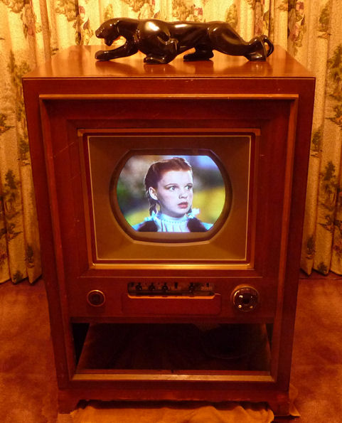
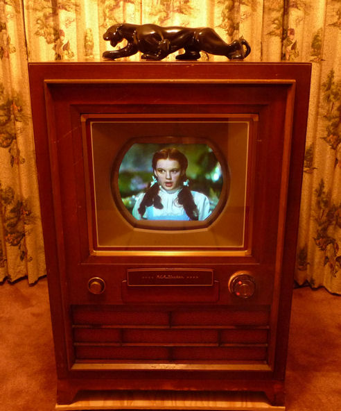

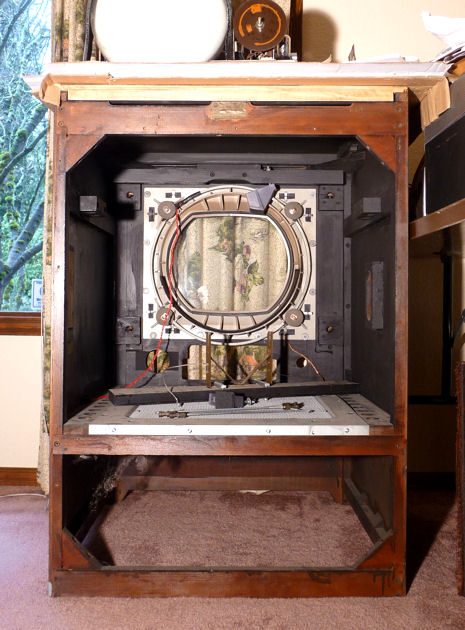
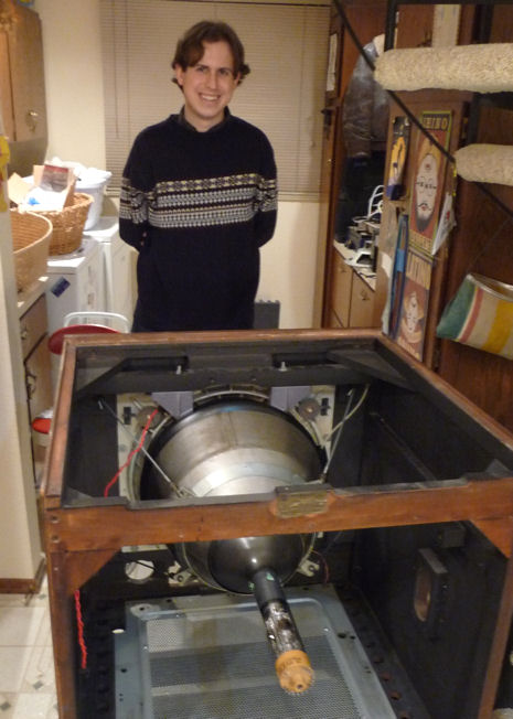
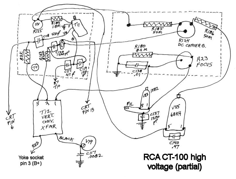


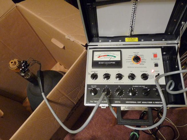

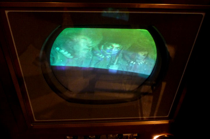
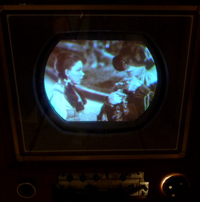
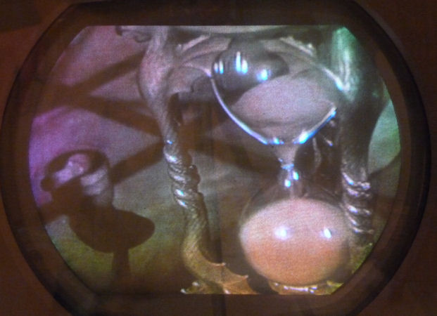
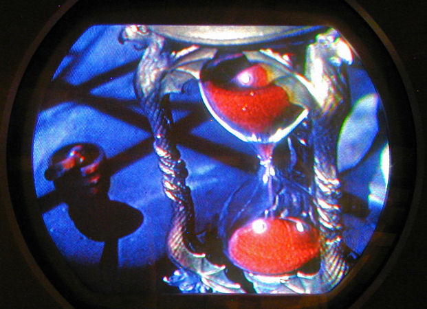
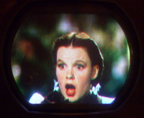

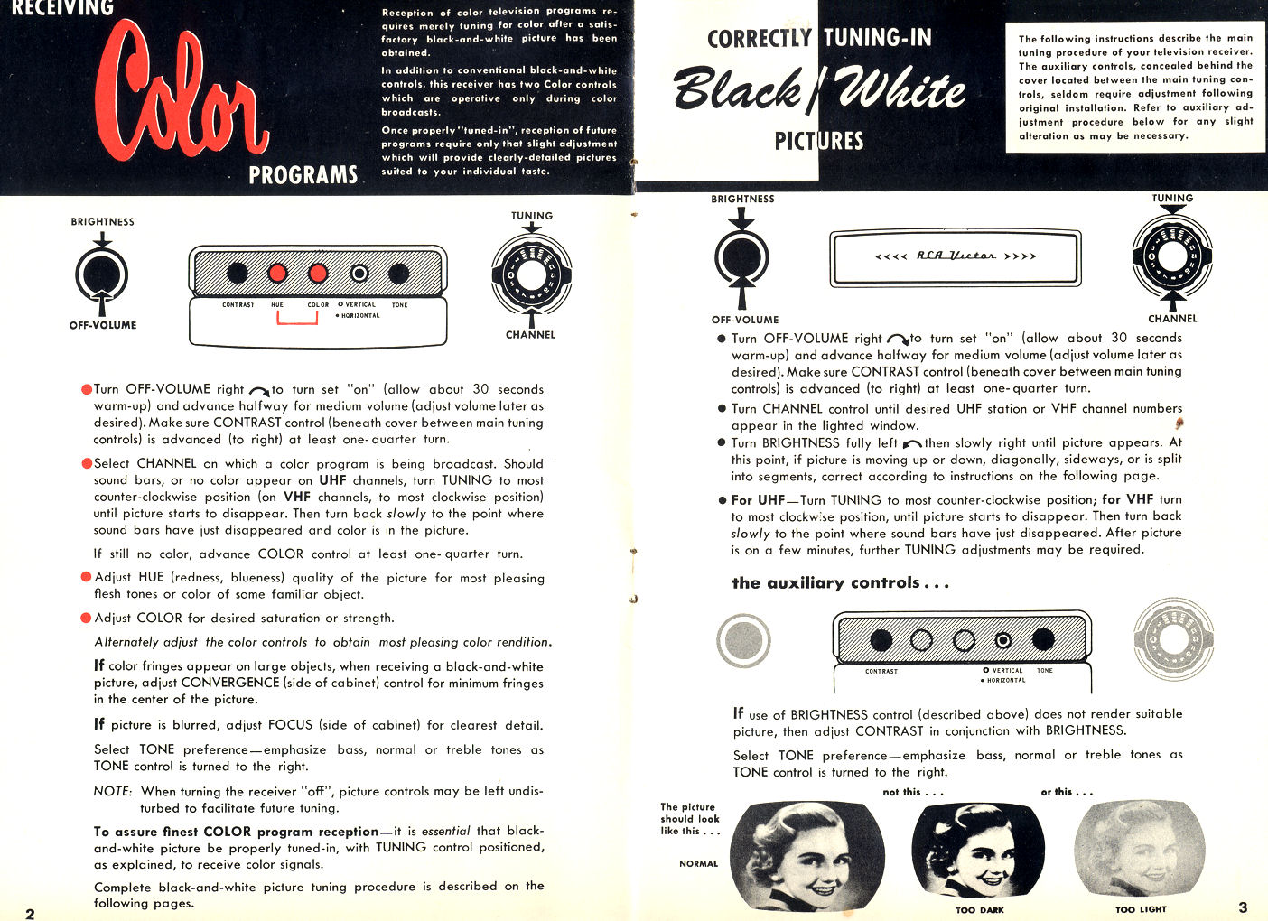
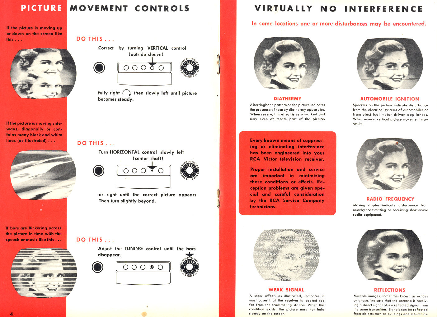
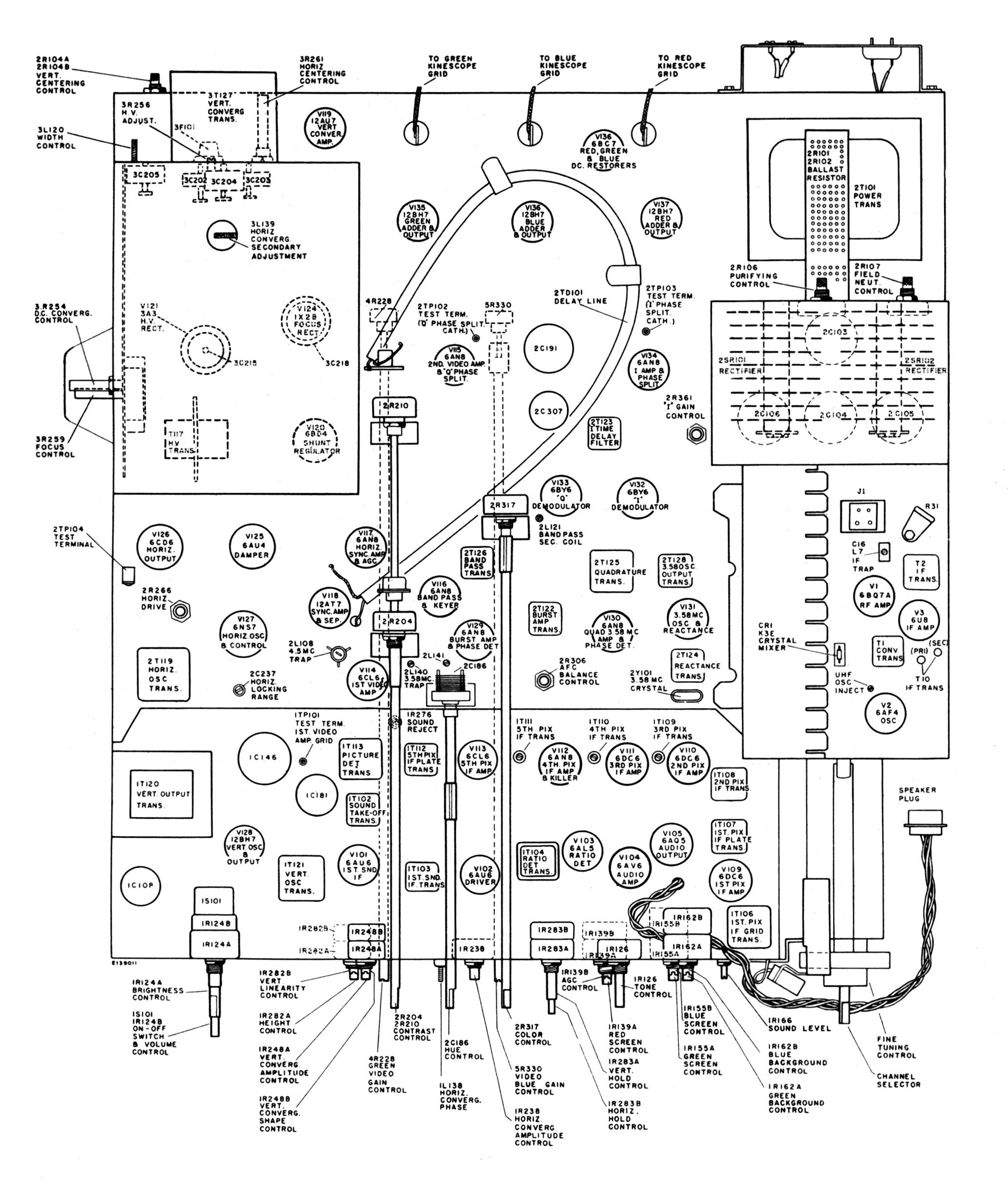
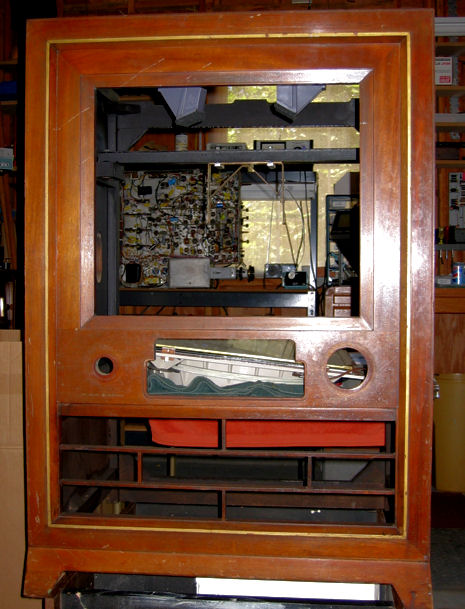
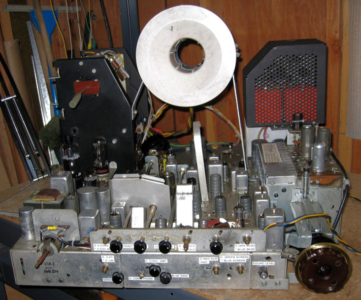


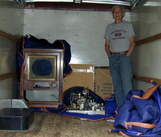
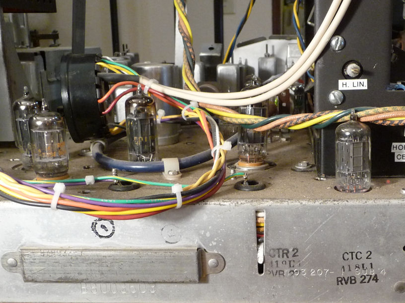

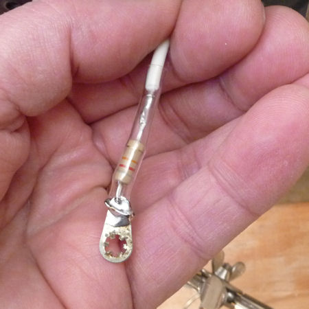
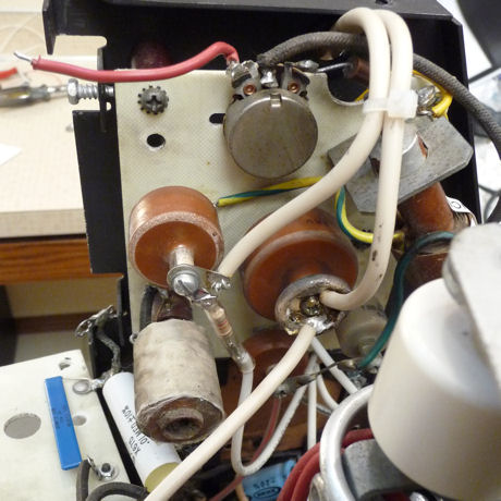
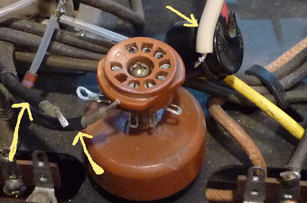
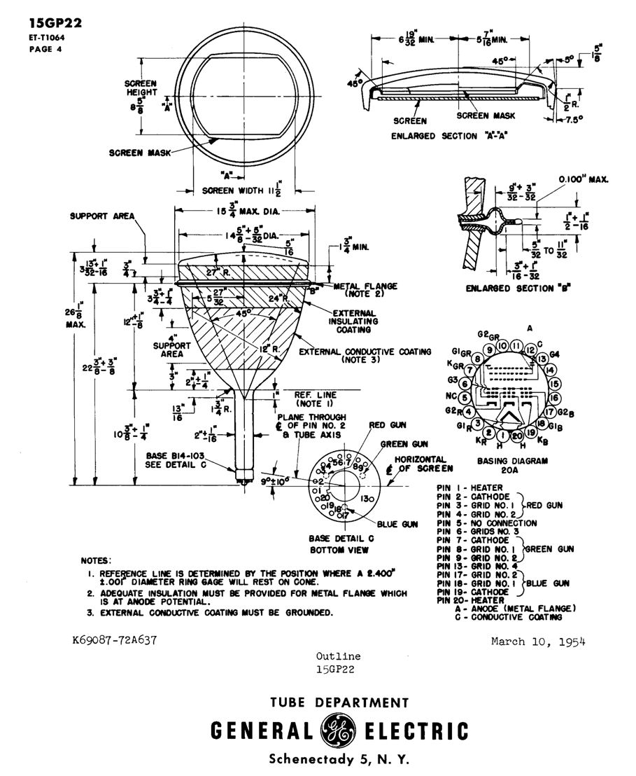
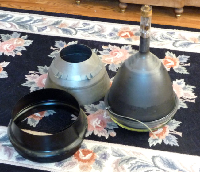
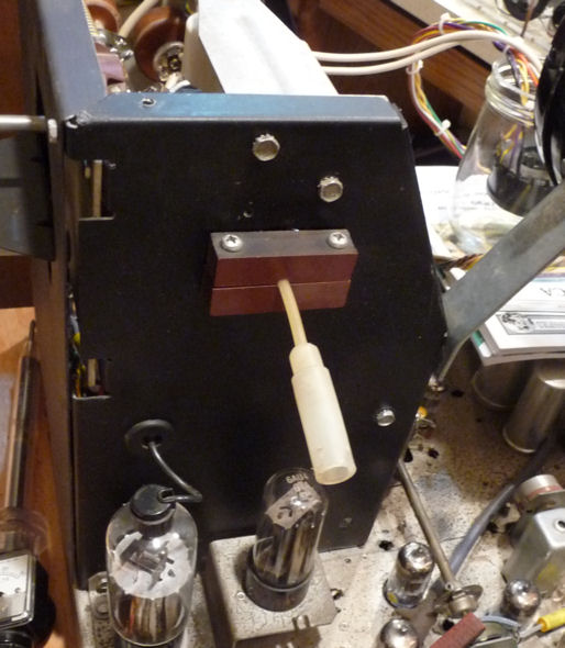
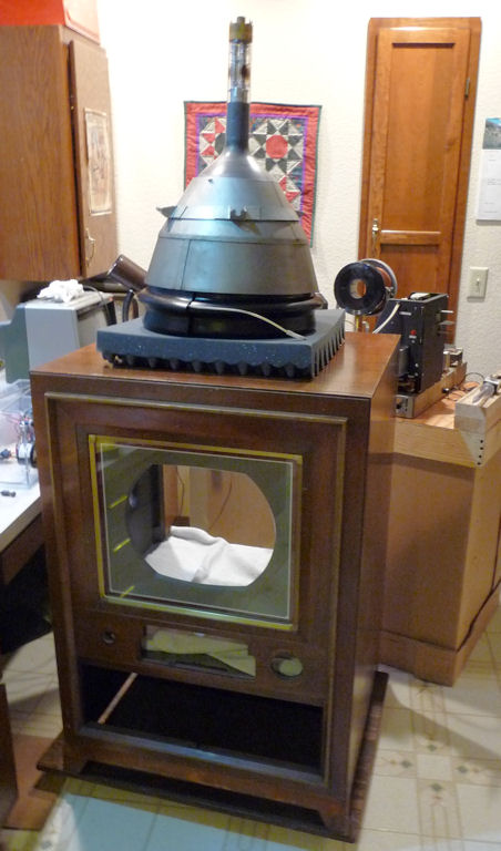
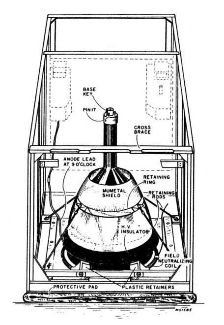
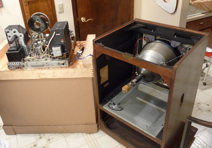
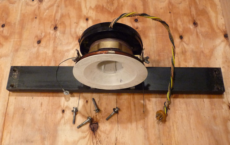
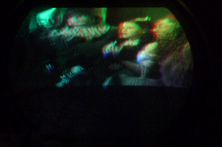
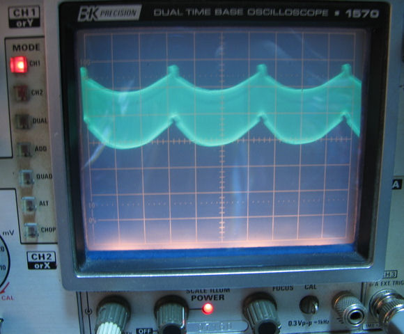
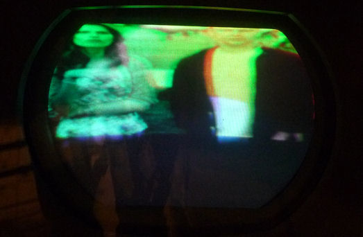

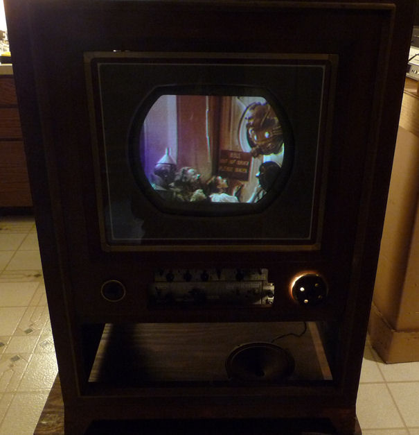
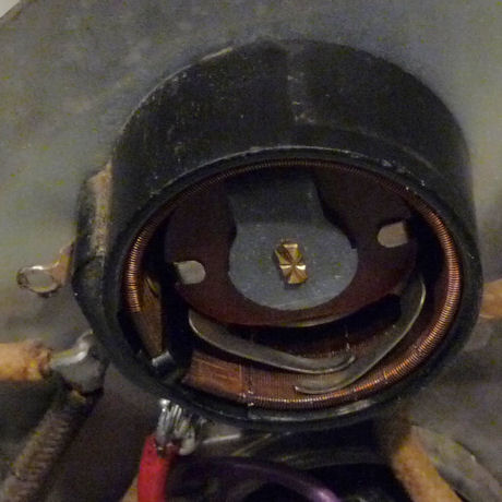
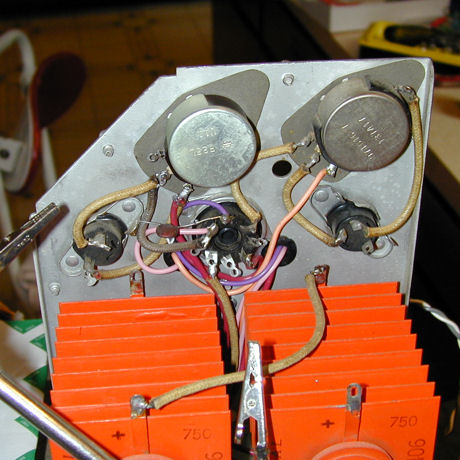
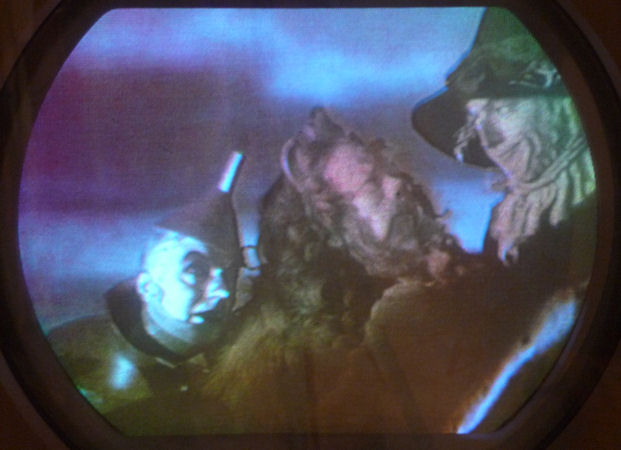
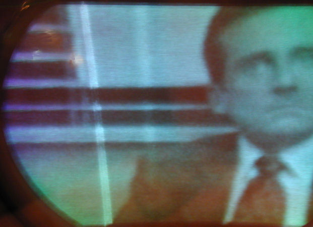
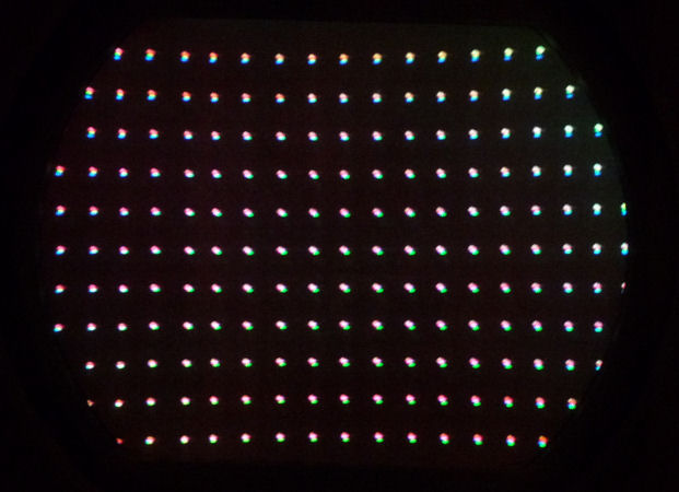
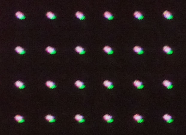
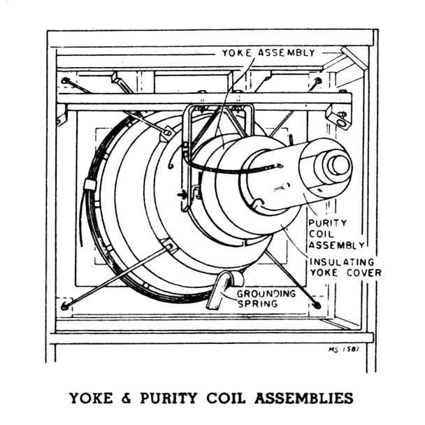

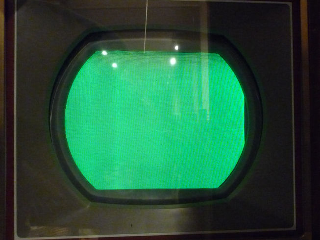
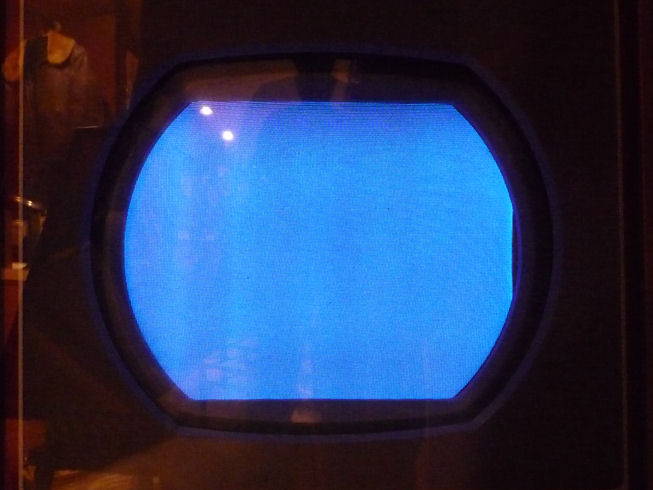
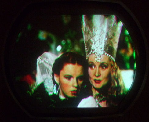
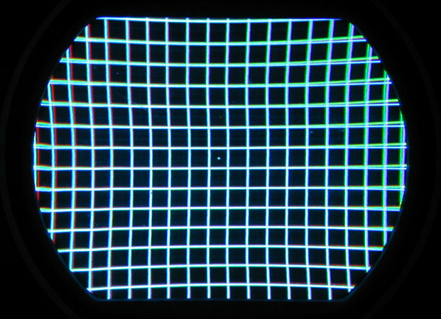
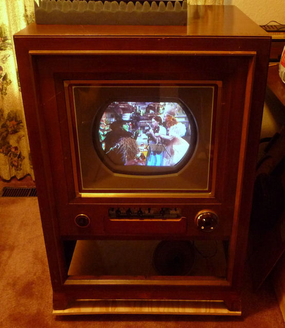
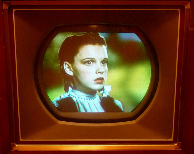
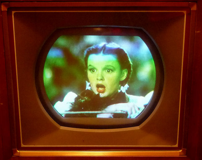

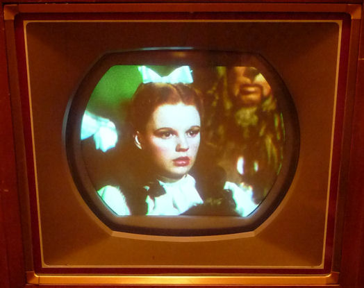
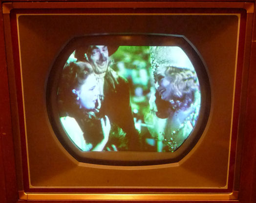
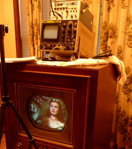
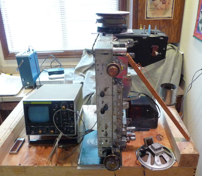


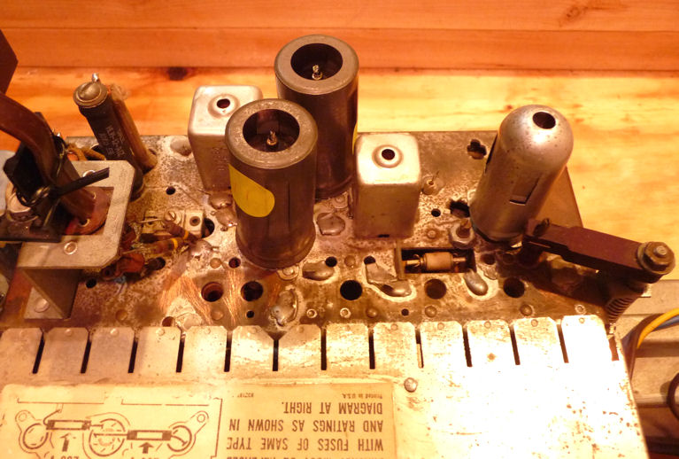
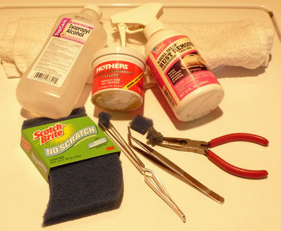

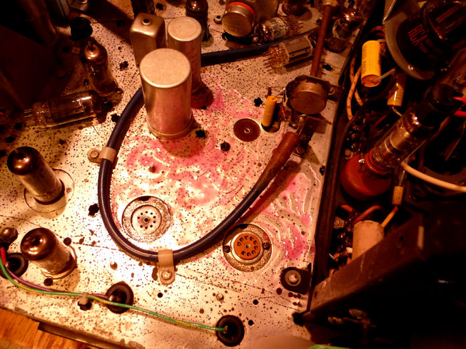
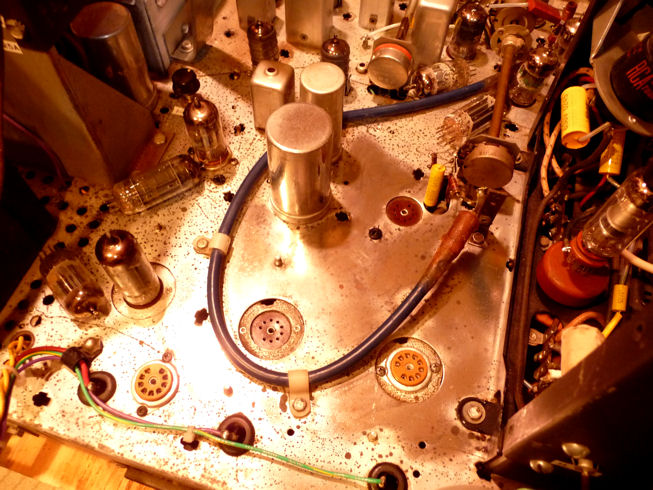
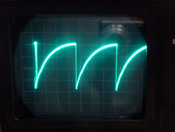
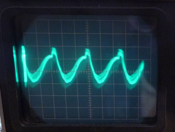
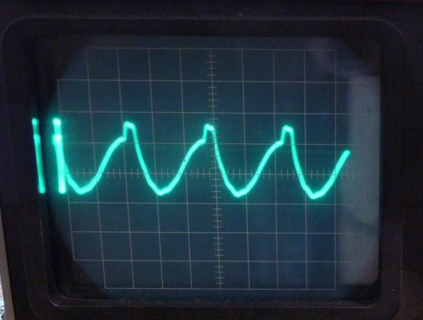
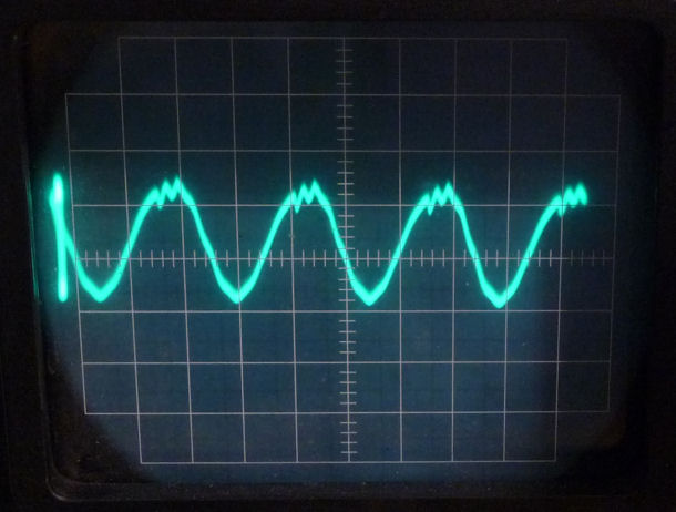
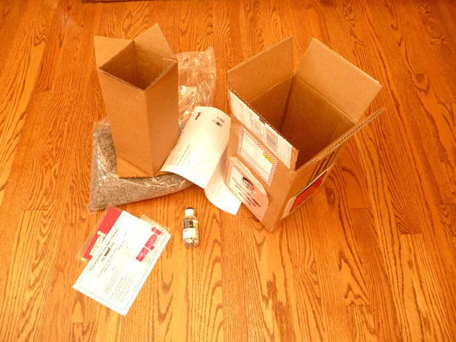
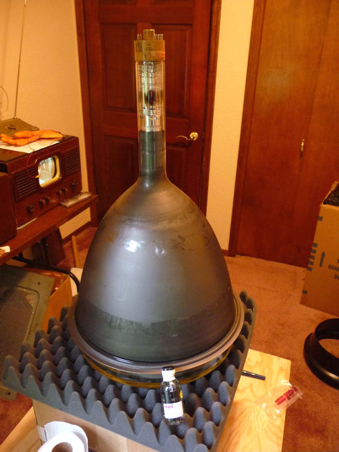


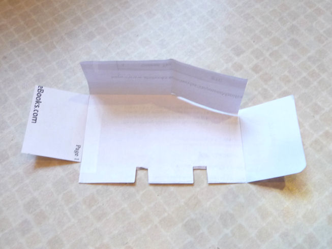
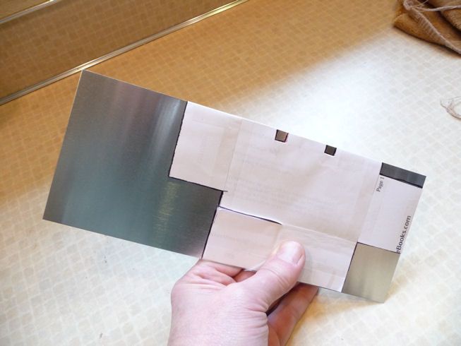
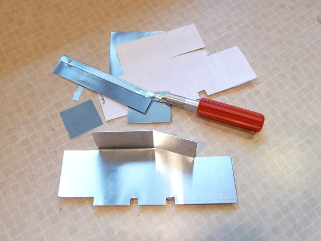
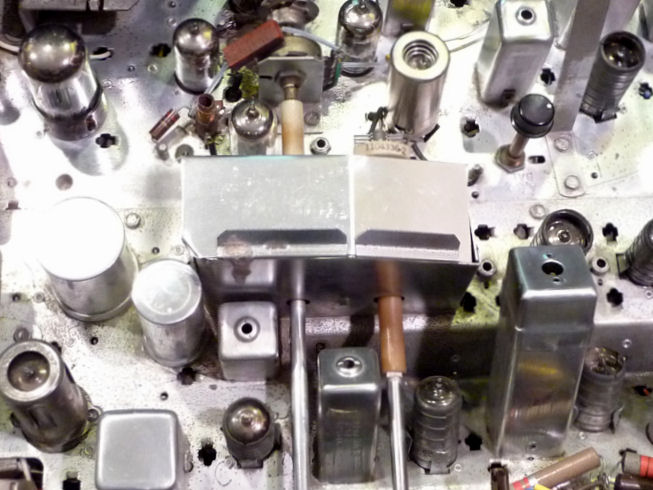
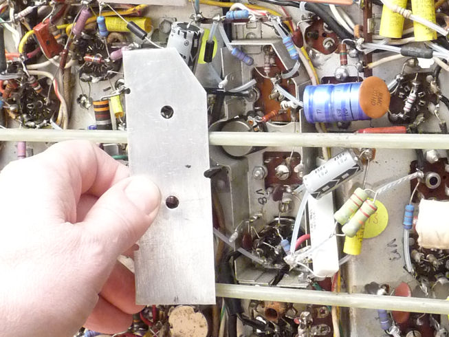
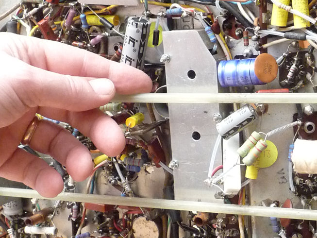

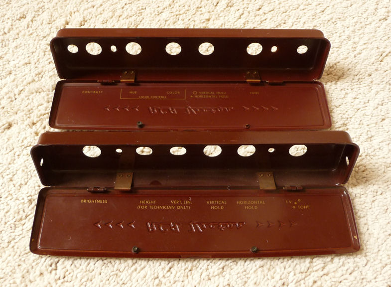
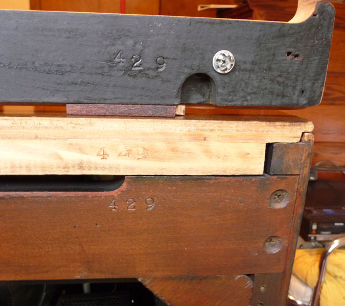

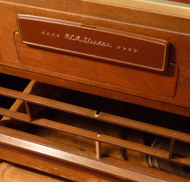
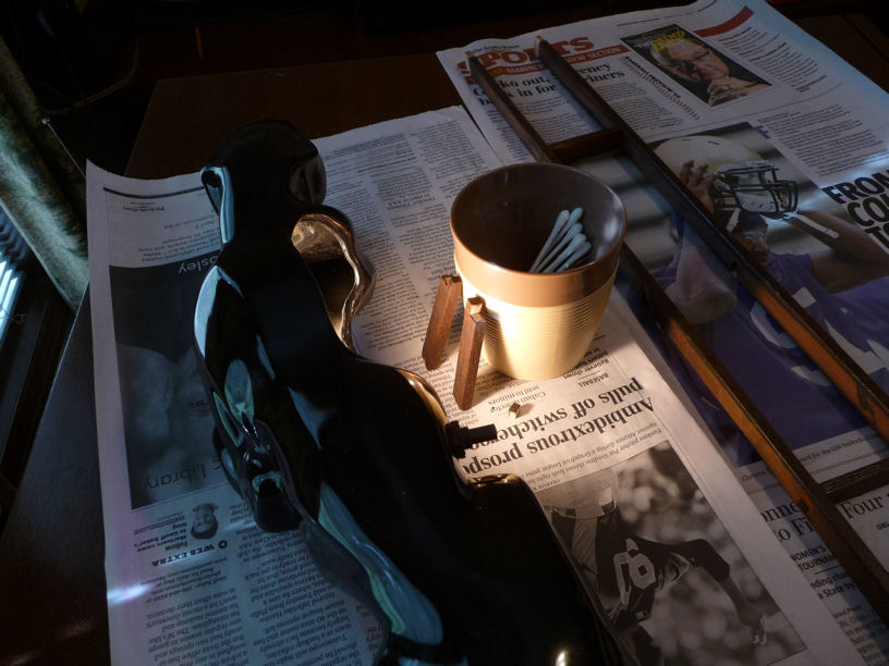
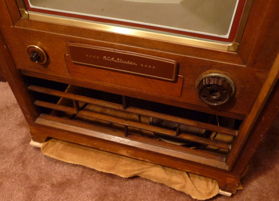
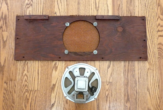
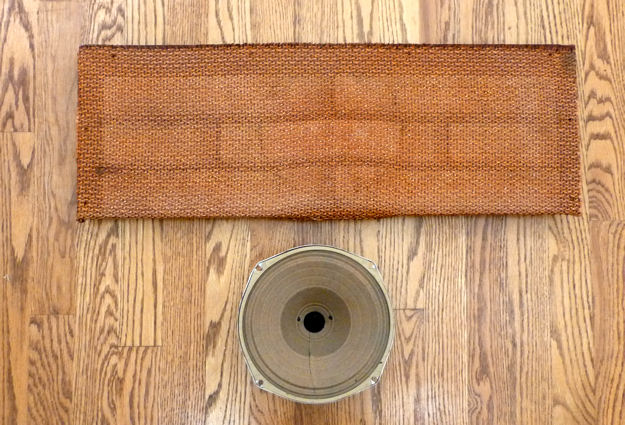
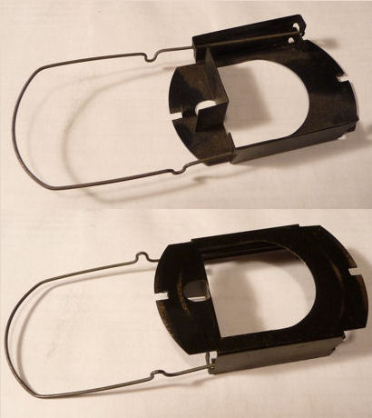
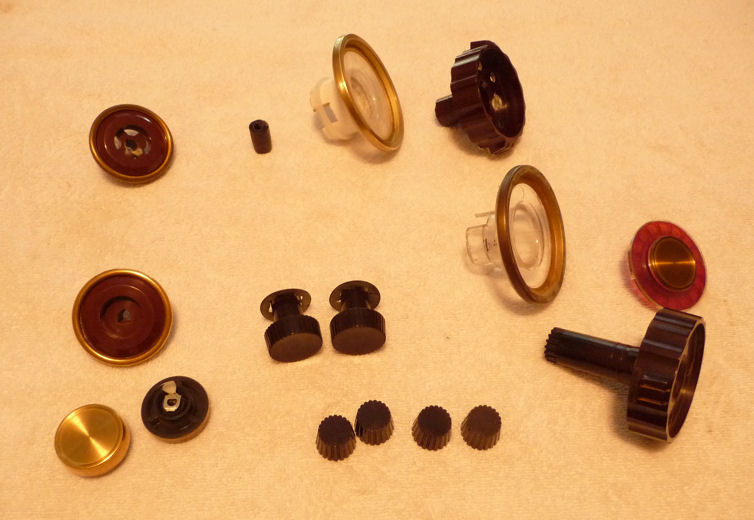
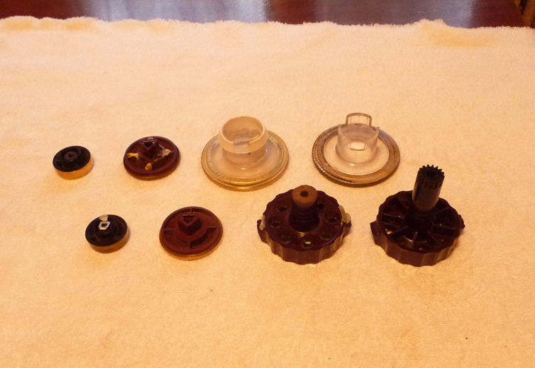
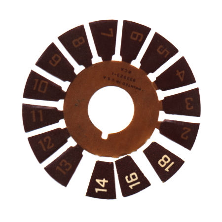
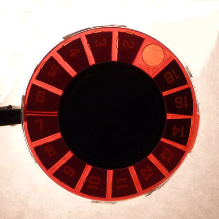
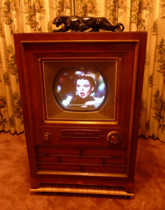
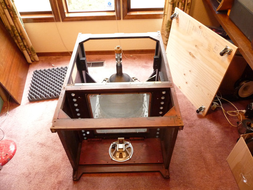
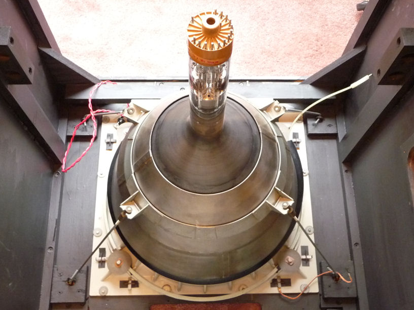
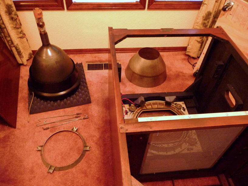

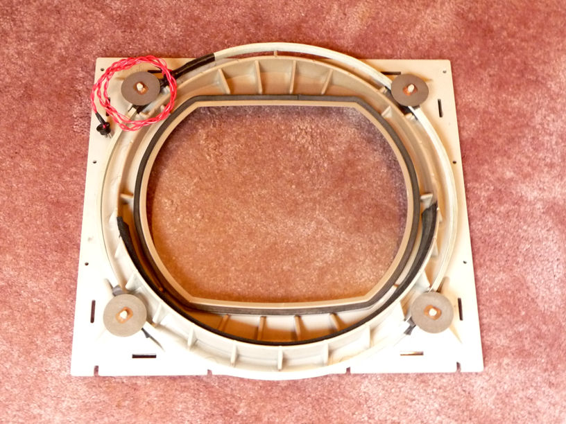
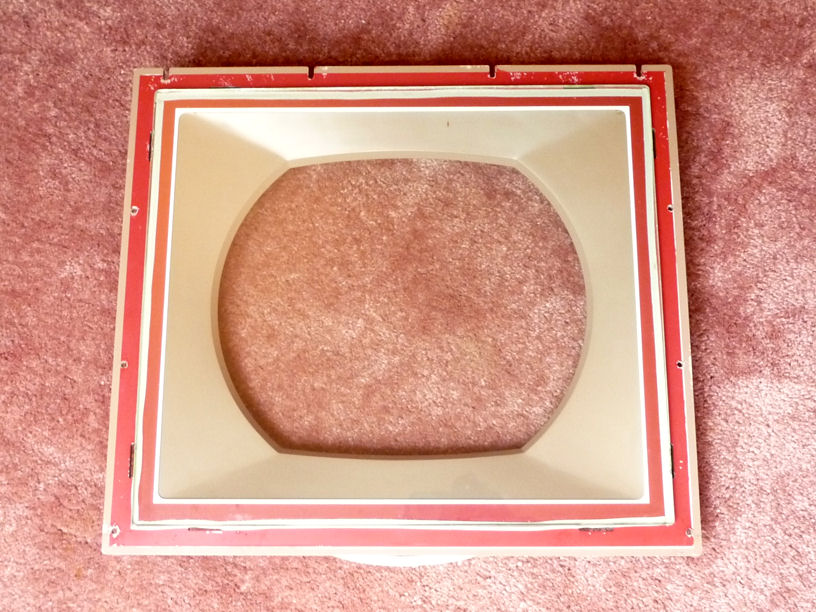
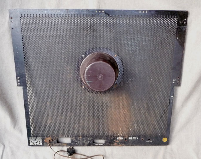
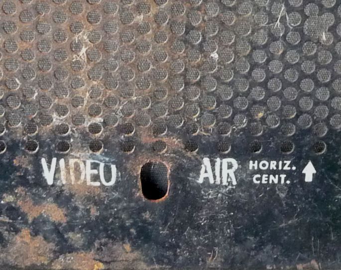
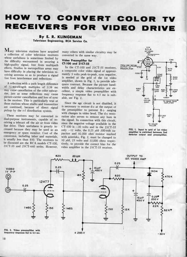
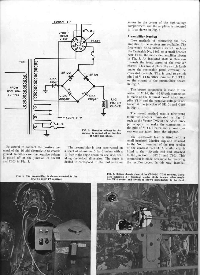
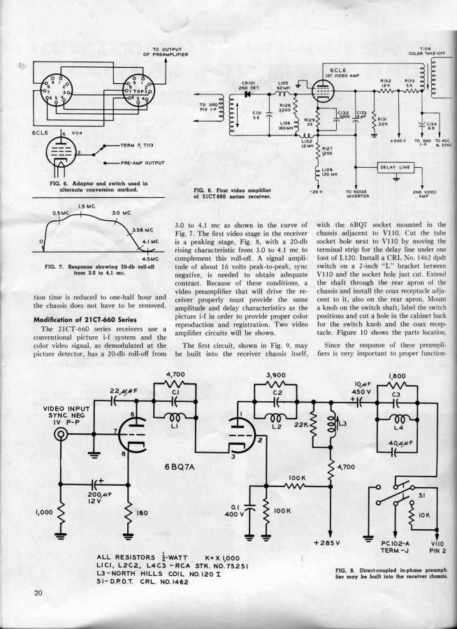
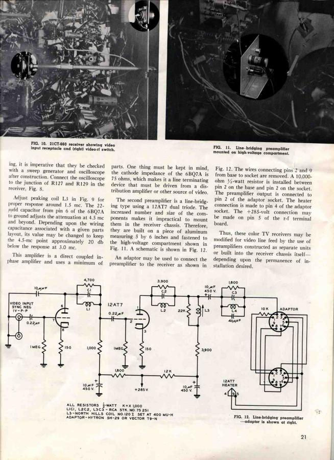
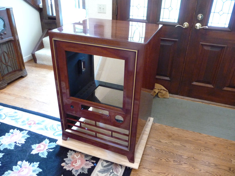

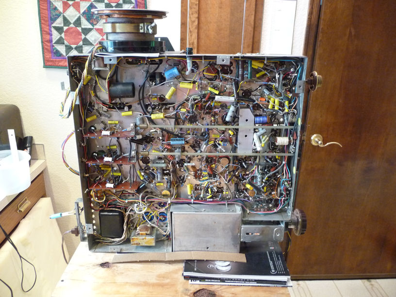
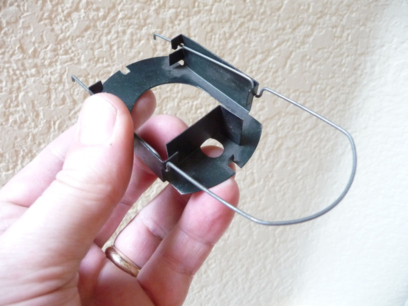
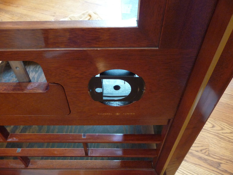
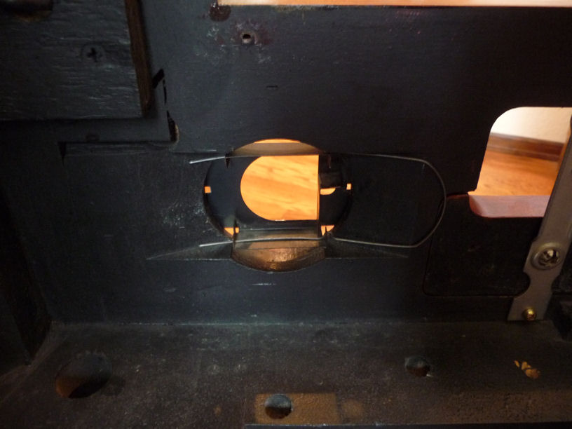
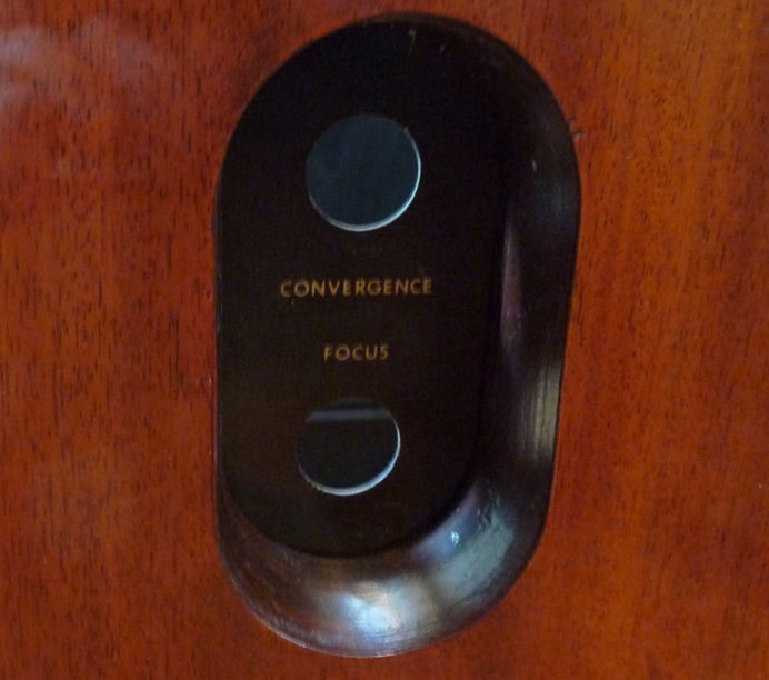
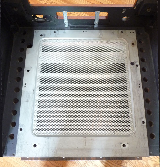


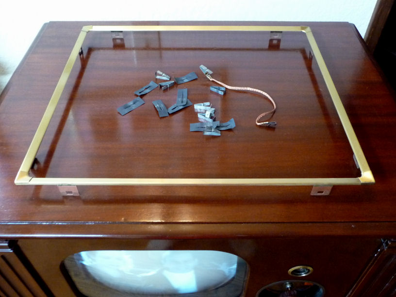

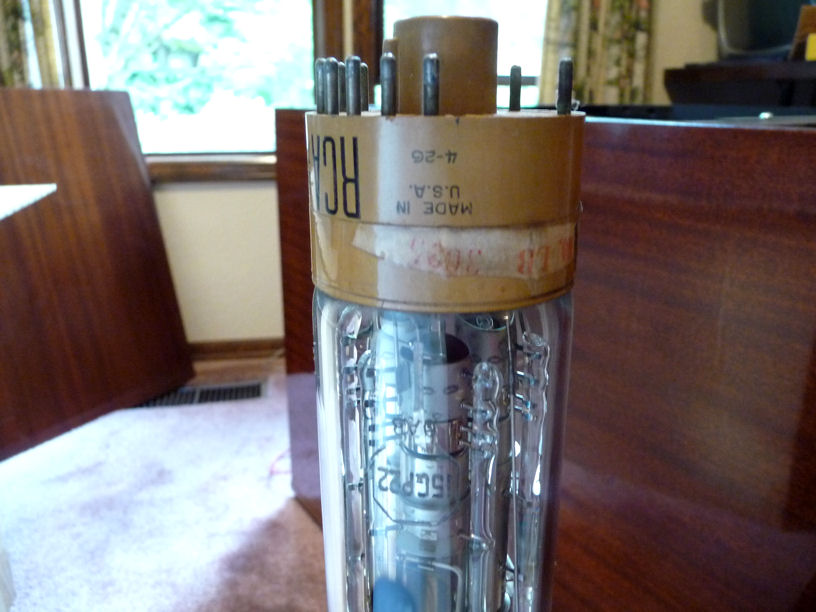
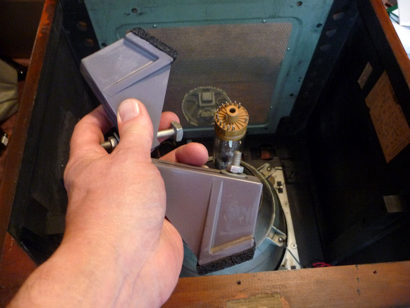
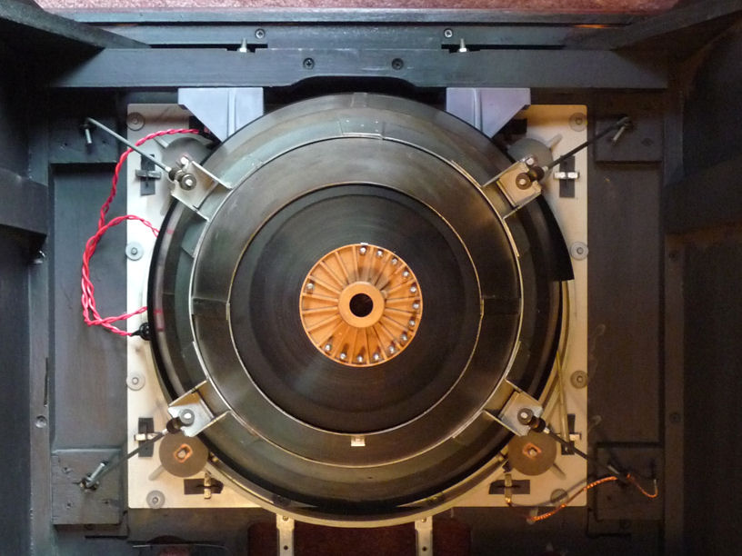
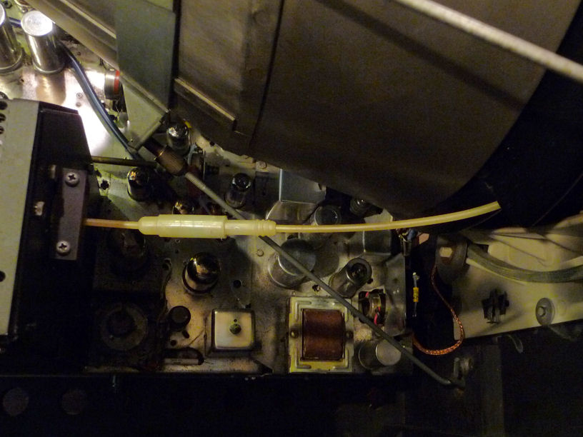
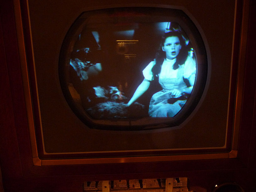
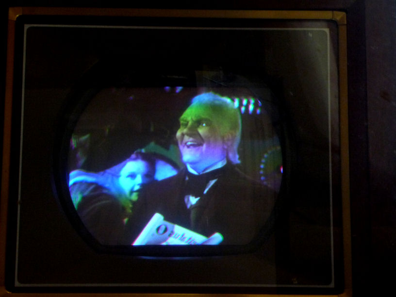
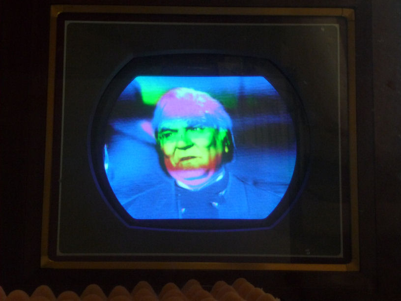
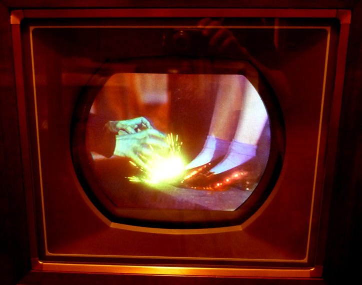
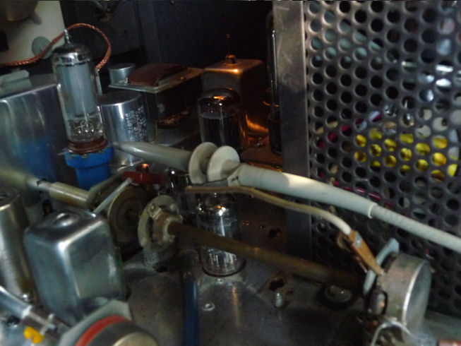
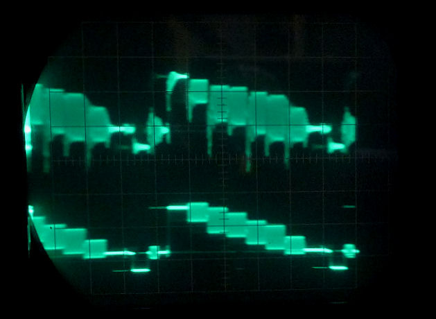
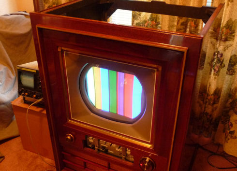
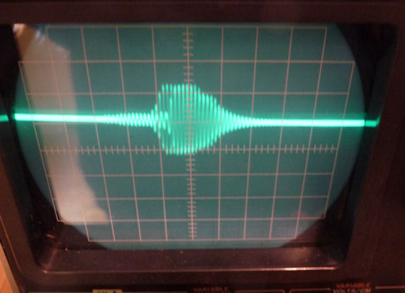
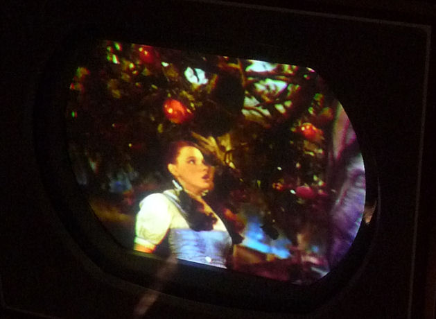
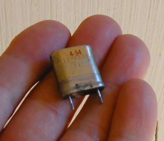

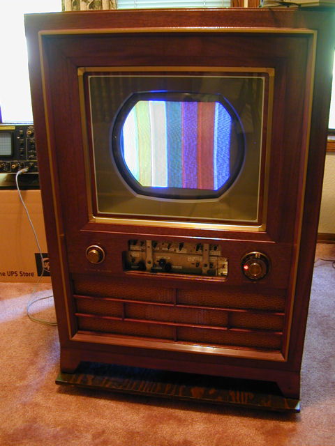
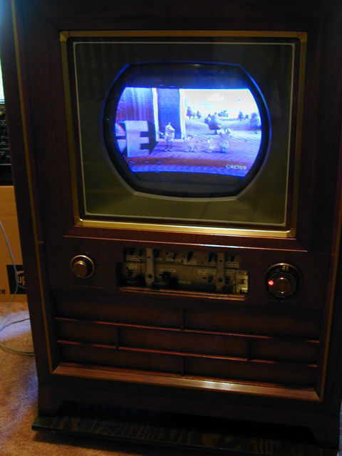
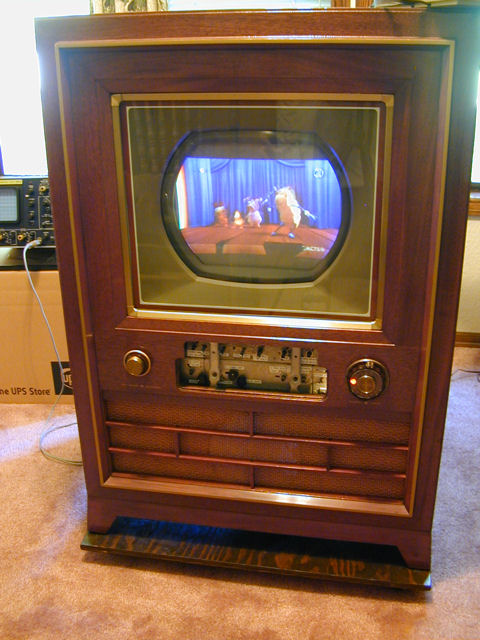
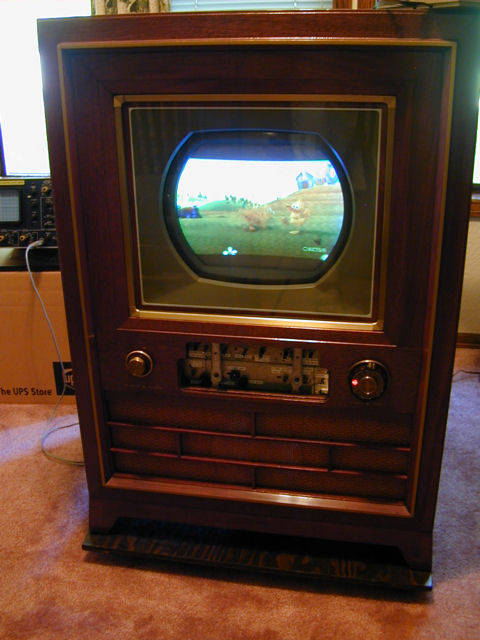
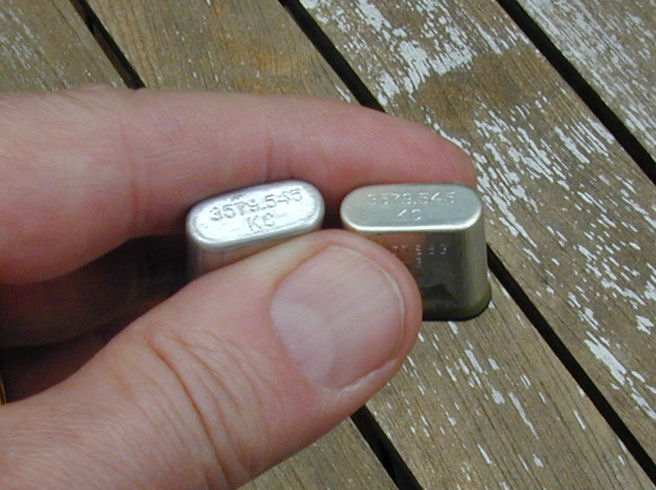
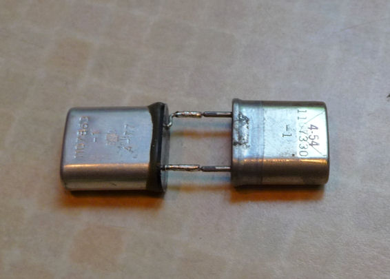
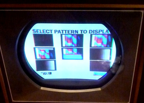
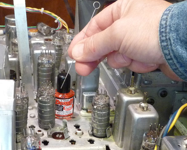
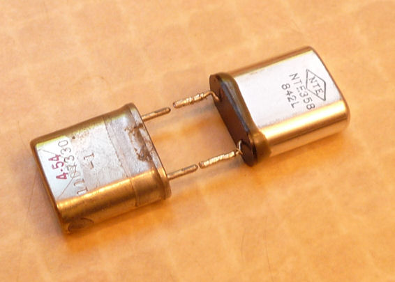
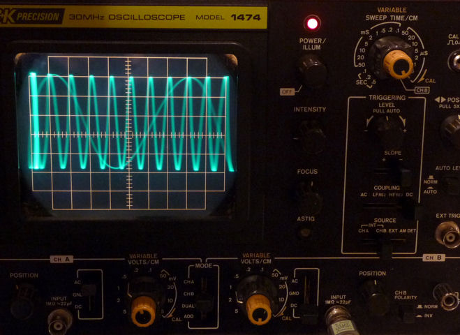
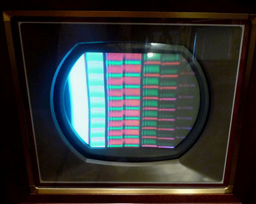
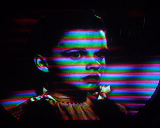
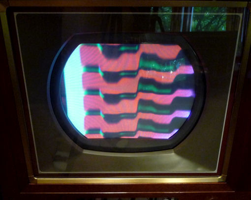
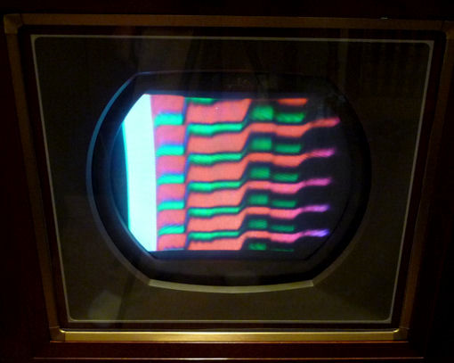
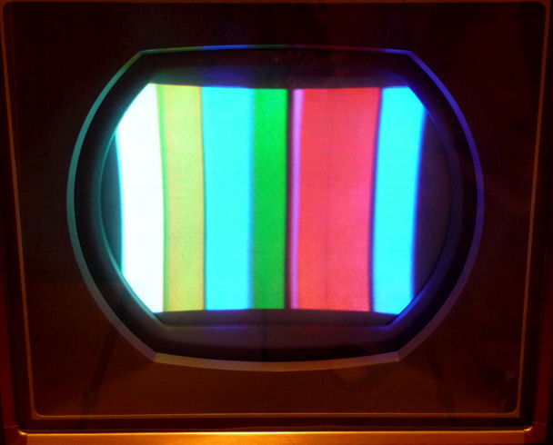
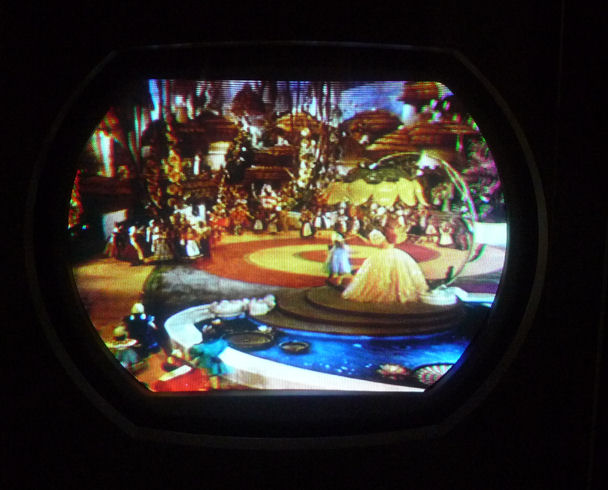
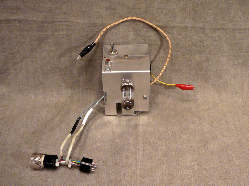
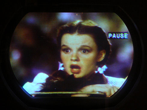
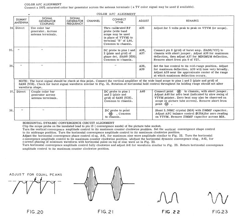