RCA 630TS Television (1946)


RCA 630: The Best-Selling Early Television
The RCA 630TS television became an immediate hit when it was introduced in
1946, right after World War II. With its large
(for the time) 10-inch screen, sleek Machine Age cabinet, and
sophisticated electronics, it established a standard for postwar television
technology and helped RCA to become a leader in that booming market.
Television existed before World War II, but in the prewar years, many US
cities had no television stations. Only a few TV models were available, and
only the very wealthy could afford to buy one.
After the war, TV broadcasting stations sprouted up like weeds, the
mass media missed no opportunity to promote television, and
consumers developed a thirst for affordable television receivers.
With an initial selling price of $435, the RCA 630TS was not exactly cheap.
You could buy a decent automobile for that price! Nevertheless, RCA sold hundreds
of thousands of 630s during the three year production run from 1946-1949.
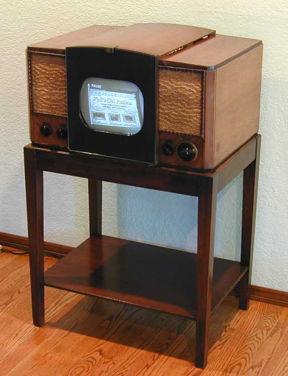
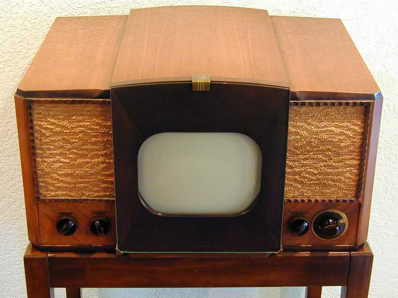
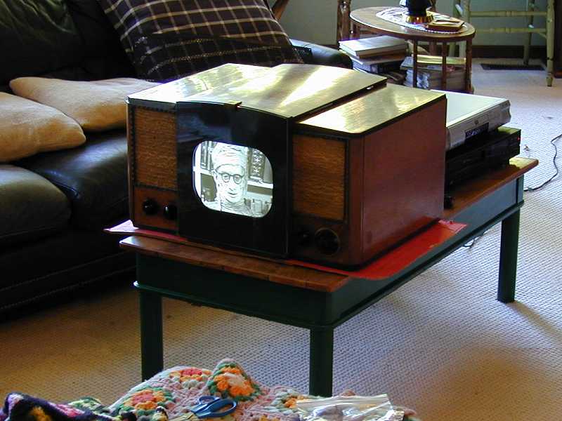
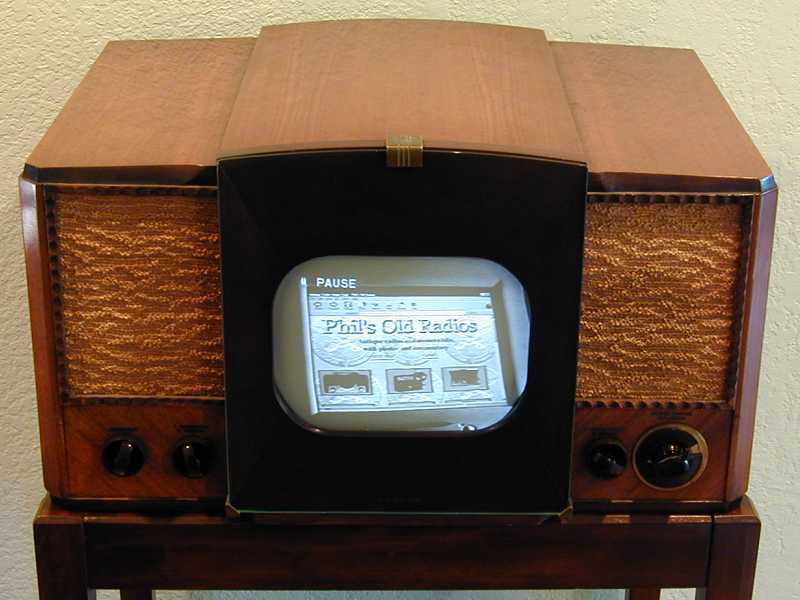
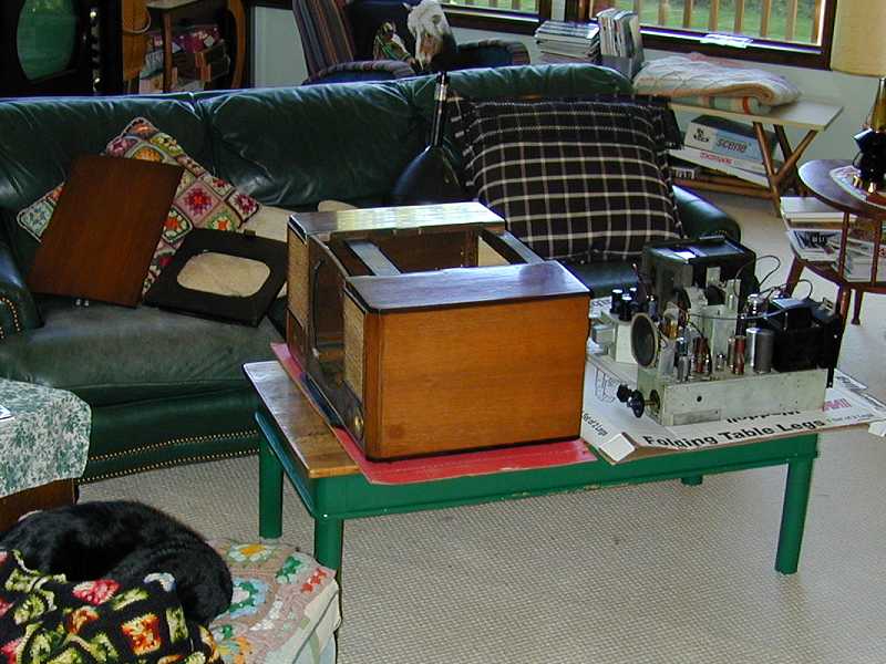
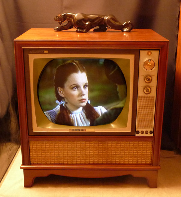
The 630TS is a tabletop television. Some, like mine, were purchased with an optional floor stand.
Here is a photo of the restored set.
Weighing 85 pounds minus the stand, this tabletop would definitely not be considered a portable.
Still, it was considerably smaller than most prewar TVs, which had small screens and tended to
be housed in mammoth console cabinets.
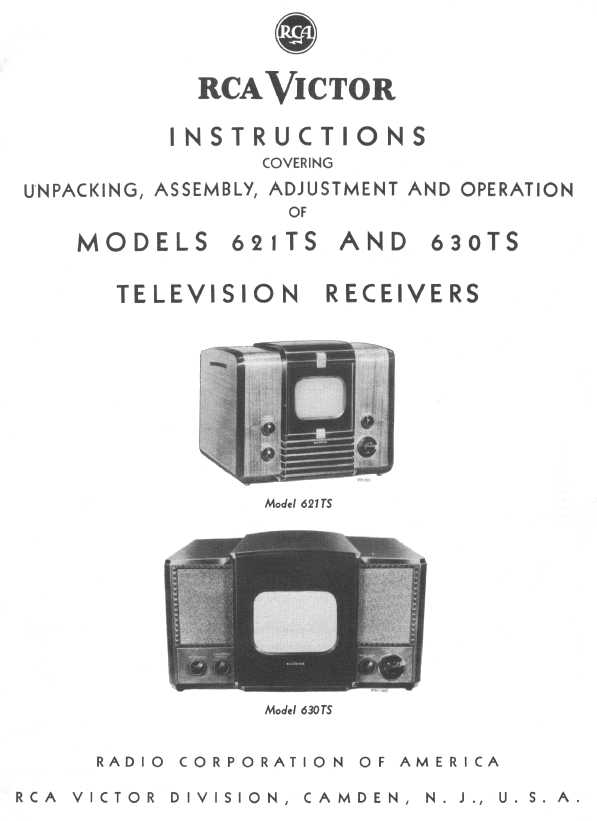
The 630TS was launched at the same time as the smaller RCA 621TS, which
had a 7-inch screen and a cabinet designed by John Vassos.
The following page from the factory assembly manual shows both sets.
The 621TS never sold in large numbers, but it is also prized by collectors
for its appealing design and compact size. Of the two, the 630TS is easier
to find at a reasonable price, and, with a bigger screen, it is more
enjoyable for daily watching.
RCA packaged the 630 TV chassis in a couple of other cabinets. The 630TCS
is the same television in a console (floor) cabinet. The 641TS
is an even larger large console with a 630
television on the top, sliding tambour doors, and a radio and
phonograph on the bottom.
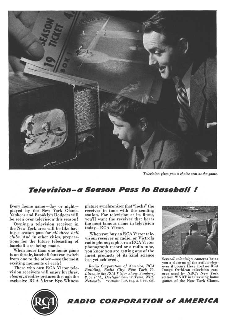
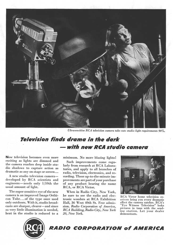
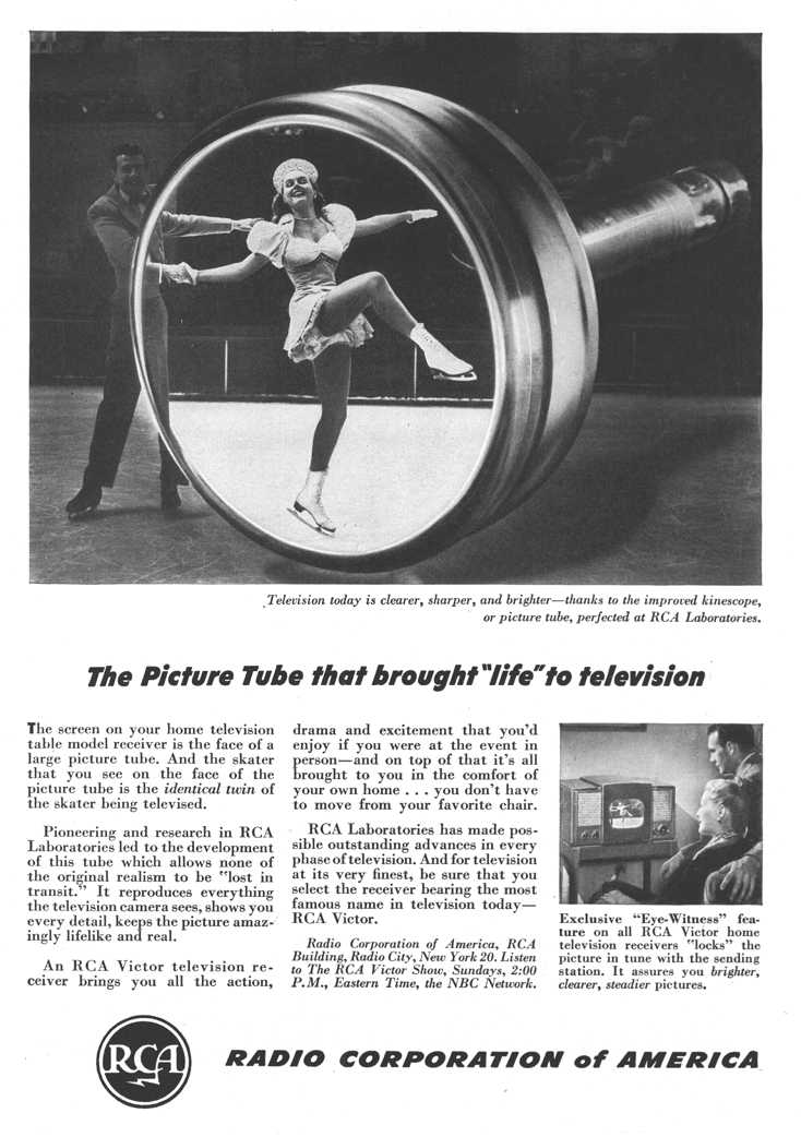
The following ads from 1947 National Geographic
promote RCA as a TV technology leader and showcase the 630TS.
Similar ads ran in other publications, from Life to Popular Mechanics.
Besides selling TVs under its own brand, RCA licensed the 630 electronic design
to other manufacturers, who sold thousands of clones.
Crosley and FADA both produced exact copies of the 630TS, some with chassis
built by RCA. About a dozen others sold 630-based televisions,
sometimes with variations such as a different tuner.
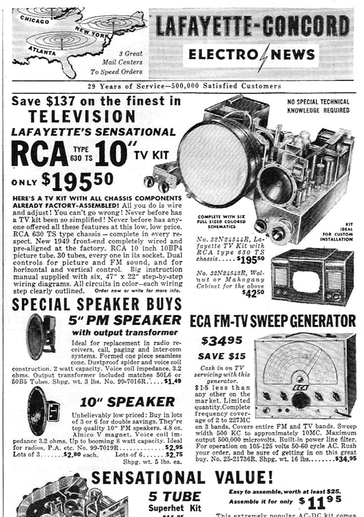
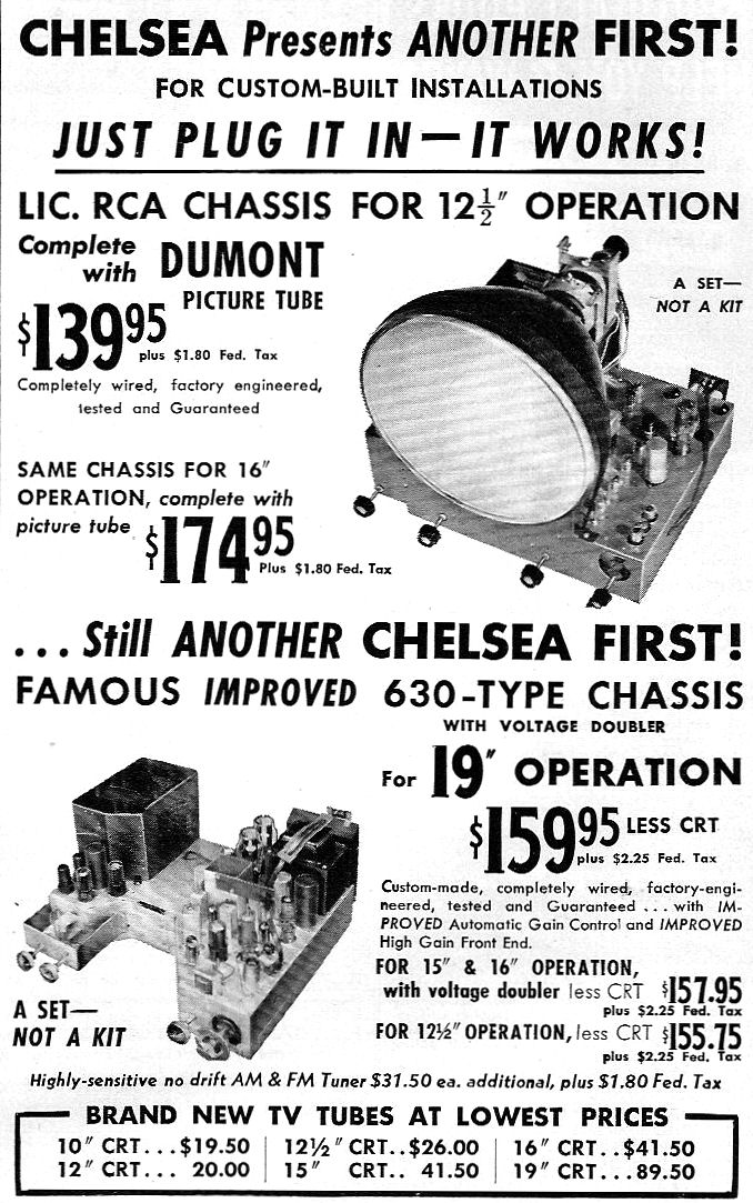
Various companies offered a 630 chassis either completely assembled or as a kit.
Clone chassis of the 1950s often included improvements to the 630 design, such as
automatic gain control (AGC) and larger picture tubes up to 19 inches.
Some kit companies offered cabinets of different styles, and magazines
published articles about building a custom cabinet.
RCA's liberal licensing policy helped to make the 630 perhaps the best
known, as well as the best selling, early television. Its electronic design
was explained in various books of the time, as well as in
the extensive factory service and installation manuals, which
comprise 75 pages.
Cabinet Design
The 630TS cabinet strikes a nice balance between fashion
and practicality. The sleek, understated lines typify the immediate
postwar period, when clean Machine Age designs supplanted
heavier, more ornate looks of earlier times.
Here is the 630TS in operation, showing a screen shot from the
John Ritter movie Lethal Vows, which featured an early version
of my website.

(The actual picture is black and white, of course. The blue tinge in the
previous photo comes from shooting under indoor lights without a color filter.
My digital camera doesn't accept filters, and I'm too impatient to shoot
all these photos with my old Nikon film camera.)
Like all early TVs, the 630TS needed a safety glass to protect the picture
tube. The RCA designers made the glass a feature, rather than
try to deemphasize it. The thick laminated glass is mounted in front of the cabinet,
projecting outward and highlighted by sturdy brass mounting clips.
The rounded top panel continues the profile of the front glass all the way
to the back of the cabinet. Arced slots on the underside of this panel
provide extra ventilation.
When you disassemble this TV for service, you'll learn more about why it
was built this way. The picture tube is not entirely supported by the
chassis. Instead, it is attached both to the chassis in
back and to the cabinet in front. To remove the picture tube or
chassis you need to take off the arched top panel as well as the
front safety panel, then slide the picture tube out from the front
of the cabinet.
The cabinet design was dictated in part by the TV's
electronic design, in other words.
Quality is evident in the cabinet construction. For example, the front
panel holding the safety glass is made of solid walnut, with a beveled
interior circle to fit the picture tube's face, and a
lip projecting below to fit a slot in the bottom
front of the cabinet.
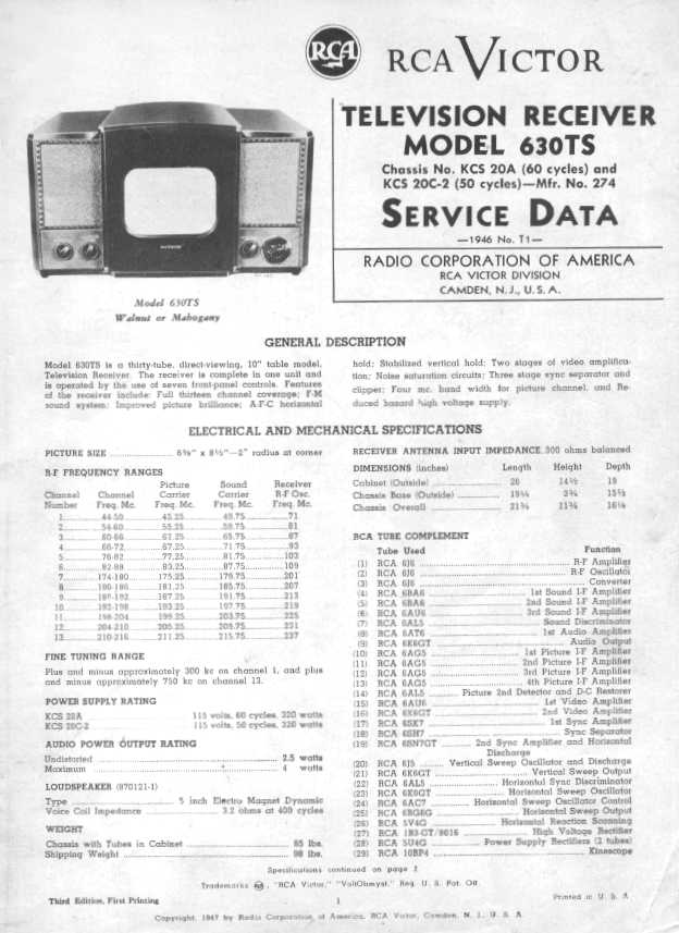
Electronic Design
As noted earlier, the 630TS electronic design was an exemplar for its time.
Here is the first page of the factory service manual.
You can download both RCA factory manuals from the following URLs:
Installation and Assembly Manual (60 megabytes)
Service Manual (90 megabytes)
These are very large files—150 megabytes combined. To download a file, right-click
on the URL and save it to your hard disk. The image quality is better than in the
screen capture shown above.
The 630TS receives 13 channels, including Channel 1, which became obsolete soon after World War II.
There are seven controls on the front of the cabinet, for brightness, vertical and horizontal hold,
power/volume, channel selector, fine tuning, and "picture."
The picture control is what we would now call a manual gain control.
Later TVs have extra circuitry for automatic gain control, or AGC, which
automatically adjusts the strength of the TV signal
when you switch between strong and weak stations.
The 630TS uses 30 tubes, including a 10-inch electromagnetic-deflection
picture tube:
| Tube |
Type |
Function |
| V1 |
6J6 |
RF amplifier |
| V2 |
6J6 |
RF oscillator |
| V3 |
6J6 |
Converter |
| V4 |
6BA6 |
1st sound IF amplifier |
| V5 |
6BA6 |
2nd sound IF amplifier |
| V6 |
6AU6 |
3rd sound IF amplifier |
| V7 |
6AL5 |
Sound discriminator |
| V8 |
6AT6 |
1st audio amplifier |
| V9 |
6K6GT |
Audio output |
| V10 |
6AG5 |
1st picture IF amplifier |
| V11 |
6AG5 |
2nd picture IF amplifier |
| V12 |
6AG5 |
3rd picture IF amplifier |
| V13 |
6AG5 |
4th picture IF amplifier |
| V14 |
6AL5 |
Pic. 2nd detector/DC restorer |
| V15 |
6AU6 |
1st video amplifier |
| V16 |
6K6GT |
2nd video amplifier |
| V17 |
6SK7 |
1st sync amplifier |
| V18 |
6SH7 |
Sync separator |
| V19 |
6SN7GT |
2nd sync amp/horiz. discharge |
| V20 |
6J5 |
Vertical oscillator/discharge |
| V21 |
6K6GT |
Vertical output |
| V22 |
6AL5 |
Horiz. sync. discriminator |
| V23 |
6K6GT |
Horiz. oscillator |
| V24 |
6AC7 |
Horiz. oscillator control |
| V25 |
6BG6G |
Horizontal output |
| V26 |
5V4G |
Horizontal scanning |
| V27 |
1B3GT |
High voltage rectifier |
| V28 |
5U4G |
Low voltage rectifier |
| V29 |
5U4G |
Low voltage rectifier |
| V30 |
10BP4 |
Kinescope |
Split sound vs. Intercarrier Audio
When I first glanced at this tube lineup, my first question was,
"Why so many tubes?" Some of my other 1940s TVs, such as
the National TV-7W, use
as few as 22 tubes.
Part of the answer lies in the audio system.
This television uses "split sound" audio, contrasted with the "intercarrier" system, which requires
fewer tubes.
What's the difference? Simply put, the signal received by a TV carries
both video and audio information. The video and audio must be split apart,
detected, and amplified for the picture tube and speaker, respectively.
In a split sound TV like the 630TS, the audio signal is split off as soon
as possible and amplified separately from the video signal. An intercarrier TV,
however, amplifies the combined video and audio as one signal, then splits off the sound portion later.
This TV uses three stages of IF, or intermediate-frequency, amplification for the
audio signal (tubes V4-V6). The video signal goes through four stages of IF
amplification (tubes V10-V13). That's a total of seven tubes, with all
their associated components.
The intercarrier system eventually predominated. It uses fewer components,
which means lower production cost
and fewer service problems over the long run. Intercarrier audio is also
less susceptible to fine tuning errors or drift in the TV's local oscillator,
resulting in a good-sounding, easy to tune receiver.
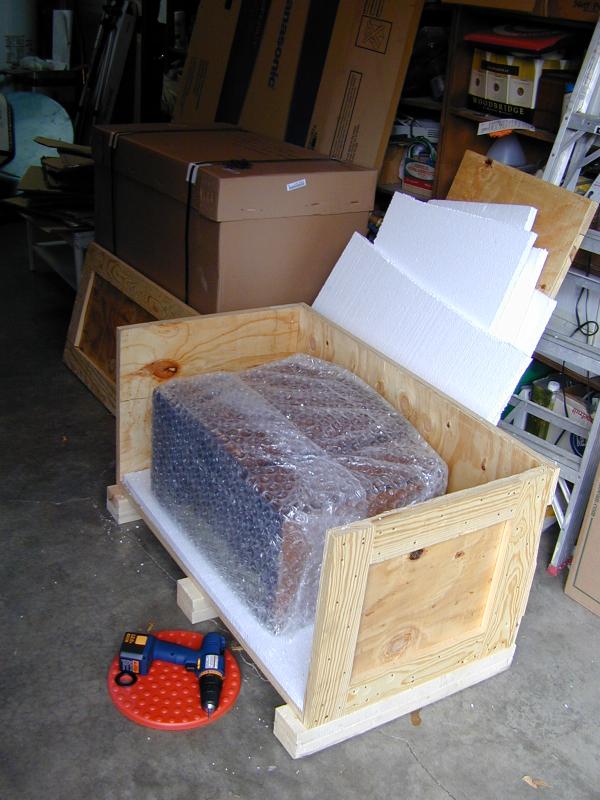
Shipping
I bought this TV in 2006 and had it shipped from St. Louis to Washington state.
The owner had gotten it from its original purchaser and it came with a note declaring
that it was among the first 300 televisions sold in St. Louis. The TV came with its
original wooden stand.
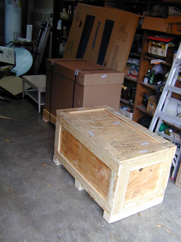
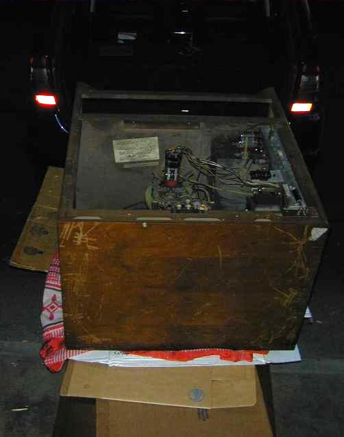
I hired Craters & Freighters to ship this large, heavy
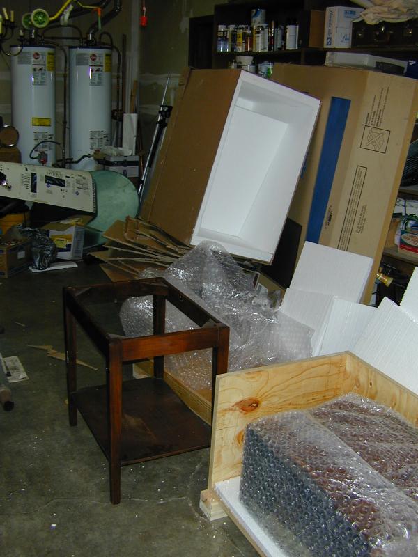
pair of items. The next photos show the process of unpacking.
The shipper built an all-wood crate for the television itself.
The lighter wooden stand was enclosed in a custom crate composed of
a wooden base with a stiff cardboard upper carton.
Both items were
cushioned with lots of bubble wrap, surrounded by layers of stiff
foam.

I was initially worried about shipping this TV without removing the chassis
from the cabinet. When I explained the removal process, this seller was not
willing to attempt it, so I had no choice. To my delight, and to the credit
of the shipper, everything arrived intact, without a scratch anywhere.
If I buy another 630TS, I would definitely find someone who could remove
the CRT from the chassis and pack it separately. Even though mine arrived
unbroken, much of the weight of the picture tube is supported by small metal
stays screwed into the cabinet.
If those little stays work loose, the CRT can bounce around in transit, perhaps
breaking its neck and damaging "unobtanium" coils inside the
chassis.
For this very reason, when these TVs were new, the RCA factory shipped the CRT in a separate box.
The assembly manual describes in detail how the dealer should open the cabinet,
install the picture tube, and make initial setup adjustments.
Disassembly
Disassembling a 630TS involves more than simply loosening a few screws on the bottom
and sliding everything backwards. The chassis is bolted to the bottom of the cabinet,
but the picture tube is secured to the front of the cabinet, and must be removed first.
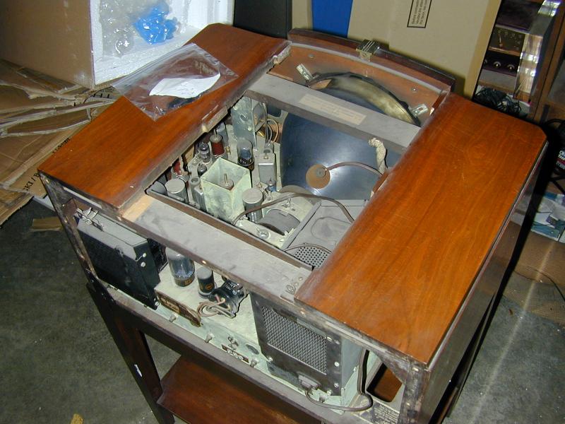
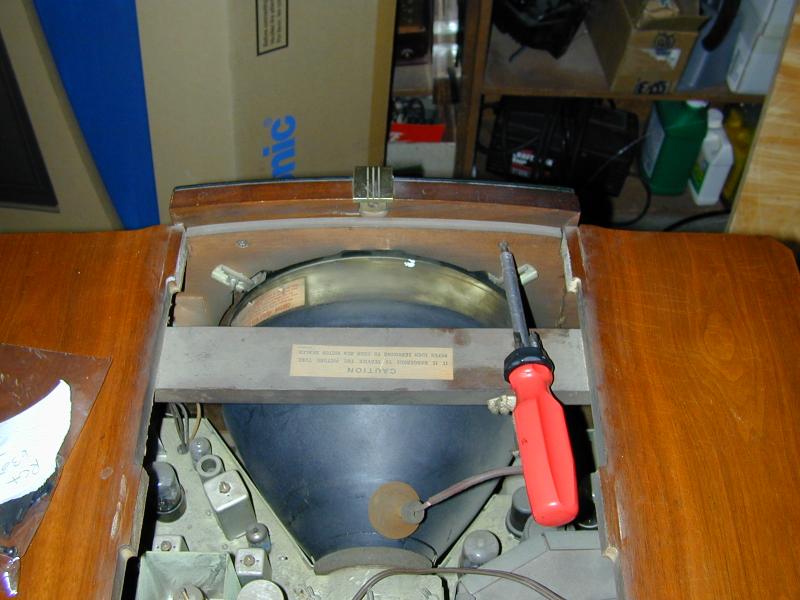
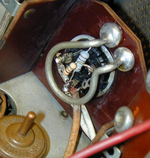
To begin disassembly, you remove the back plate and the top hatch of the cabinet.
Next, you take off the glass safety screen from the front of
the cabinet, and loosen the metal stays which steady the picture tube in the cabinet front.
Two of the stays can be seen here, in the upper corners of the CRT opening in the cabinet.
There are two more stays in the lower corners.

The curved metal stays were originally padded with rubber where they touched the tube, but the rubber bits
may have fallen off or disintegrated. When replacing the CRT, you should pad any naked stays with
something suitable, either glued-on thin rubber (as in the original) or even
a couple of licks of electrical tape.
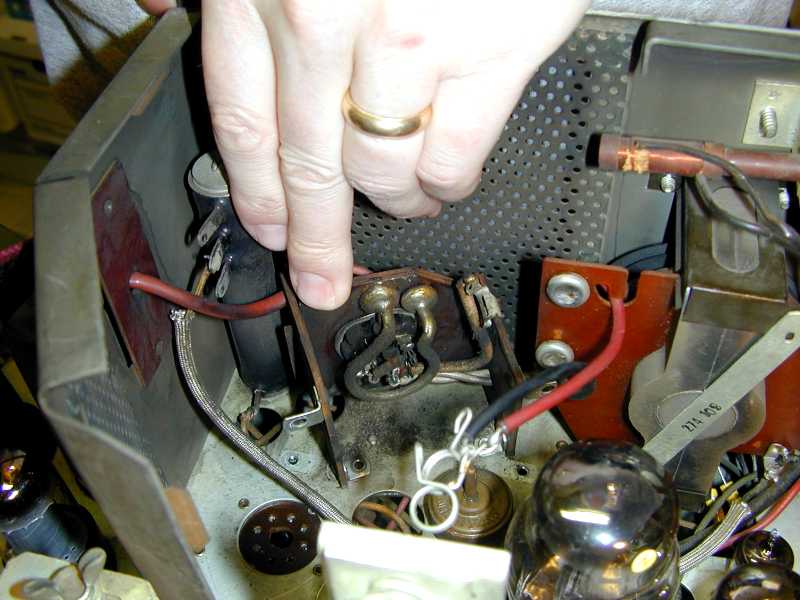
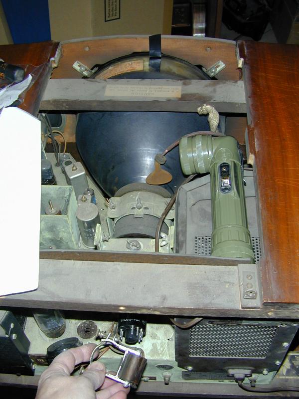
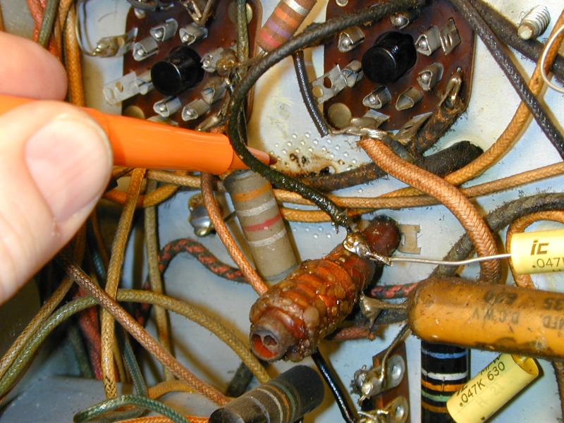
With the faceplate removed, the CRT will be drawn out through the front of the
cabinet. But first, you must unplug the picture tube from its socket and loosen
the coils around the fragile tube neck. In the next photo, I am holding the ion
trap assembly, which slides off from the back.

All of that sounds straightforward, but 60-year old TVs often harbor surprises.
As a small example, the clamp that holds the ion trap on the neck of the picture tube has
a nice little rubber pad inside the clamp to protect the CRT neck.
In my set, the rubber pad had bonded to the neck glass as if glued on with epoxy.
Perhaps the rubber slowly melted over the years from the heat of operation.
I was eventually able to remove it by completely disassembling the ion trap
and gently peeling off the rubber.
Things like that are the result of age, and you won't find them mentioned in any
service manual. You just have to be resourceful and deal with issues as they arise.
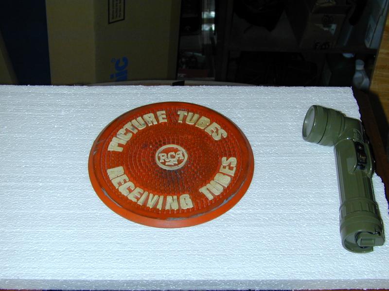
When you're removing a vintage CRT, it's nice to have a vintage rubber
picture tube mat to put it on. Hey, it's even the correct brand!

Notice how thin that CRT neck is. Handle your 10BP4 tube with care!
The bell is heavy. Always carry the CRT by
grasping the front with two hands, not by grabbing the fragile neck.
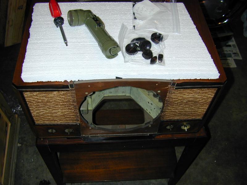
Now we remove the knobs from the front of the cabinet and the screws from underneath.
Then it's time to slide the heavy chassis out from behind.


As soon as the chassis was out, I put the faceplate, top hatch, and backplate back onto the cabinet.
The best precaution against losing screws and fasteners is to put them
back in their original places, rather than pitching them into a plastic baggie
or a cat food can.
The cabinet was in excellent original condition, with scarcely a scratch
under the vintage dust. The stand had some
scuffing on the lower shelf, and a small paint blob on one leg,
but those things were easy to touch up. The paint blob simply
rubbed off with a soft cloth dipped in "Goof Off 2" solvent.
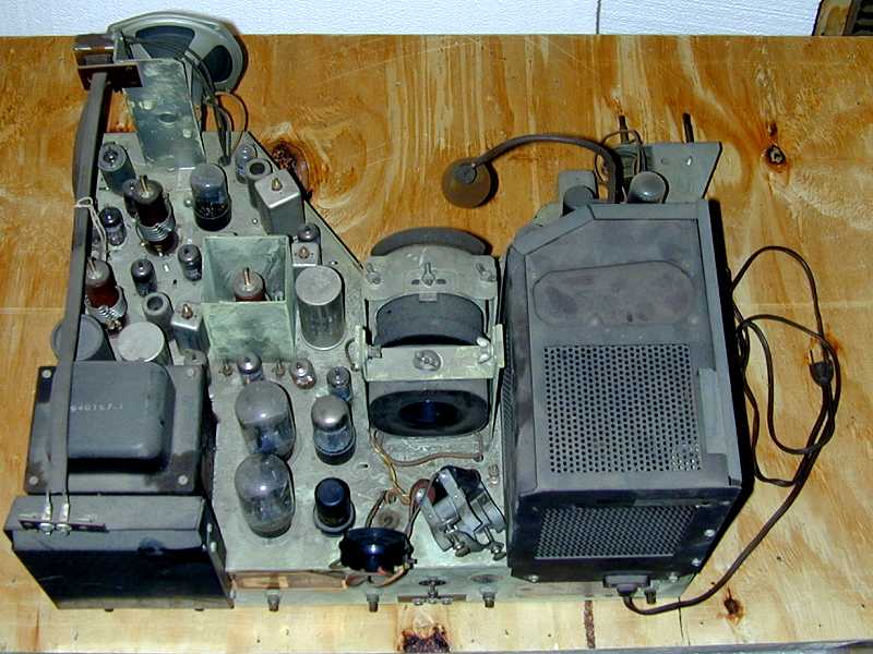
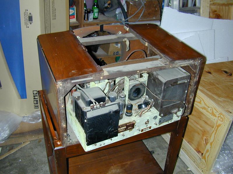
Here is the chassis after removal. On the right is the large cage for the high
voltage components. At lower left are the hefty power transformer, and, behind it,
a flattish metal cage for high-wattage bleeder resistors. We'll peek inside
that second cage later on.
As noted earlier, the chassis provides no support for the
heavy front of the CRT. To test the TV on the workbench, I will have to fashion a temporary support
for the picture tube and be very careful when sliding it in and out of the chassis.
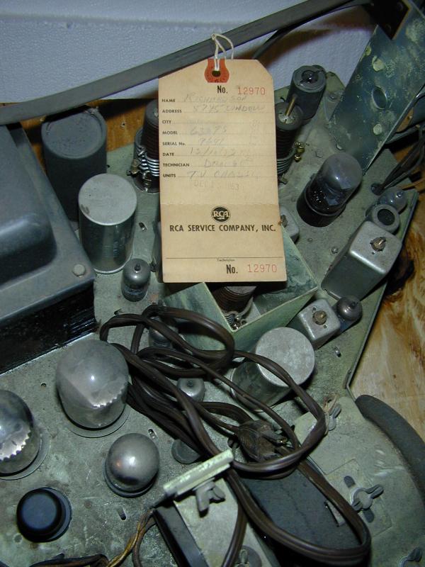
Check out this RCA factory service tag, dated 1953.
I love finding old documentation of this type.

Electronic Restoration
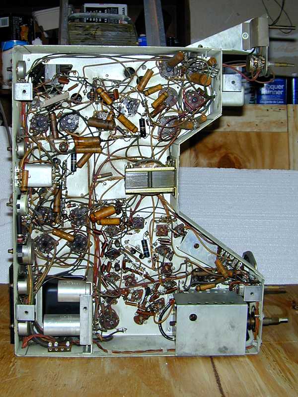
With the chassis out, it's time to get busy on the electronics. Here is
the underside of the unrestored chassis.
The initial steps, as usual, are to check the tubes, clean all the controls with DeOxit,
and replace the old paper and electrolytic capacitors.
The 10BP4 picture tube was in quite good condition (I tested it in another working set
that uses the same CRT). Nine of the remaining 29 tubes were either weak or dead,
requiring replacement.
Replacing Capacitors
I always begin restorations by replacing electrolytic capacitors. The 630TS television uses a
lot of electrolytics—14 in all—and some of them are in rather cramped quarters.
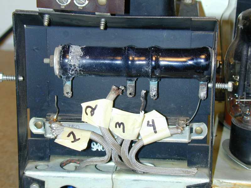
In the next photo, I have begun to disconnect some can electrolytics. Labeling the wires is a good practice.
The numbers on the tags match a sketch that I made.
If you're interrupted and return to the project hours or days later, don't assume that
you'll remember how everything was connected.

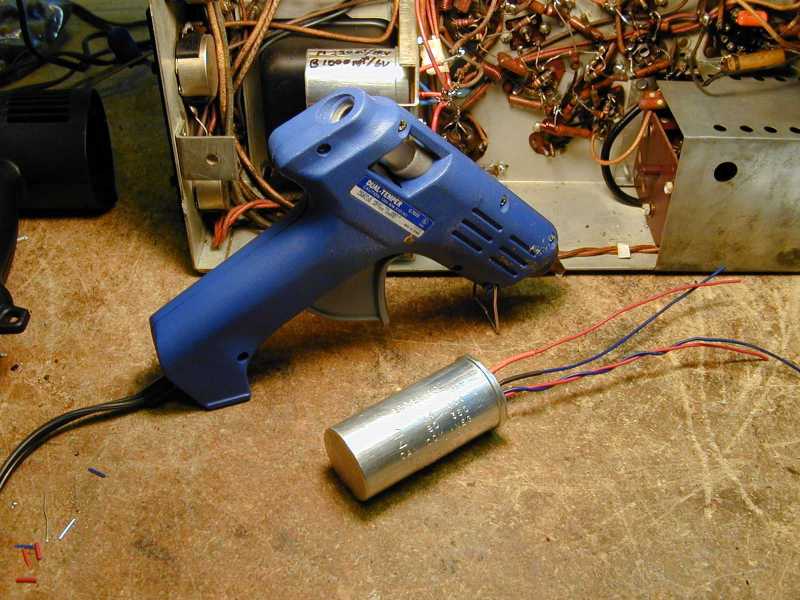
Where the available room left no
other choice, I "restuffed" some of the electrolytics in their original
cans. Here's a photo of an old can whose innards have been replaced with new caps.
The new units are secured inside the can with hot glue and the whole assembly
is ready to reinstall in the chassis.

Another restuffed electrolytic is visible in the previous photo
above the glue gun. I marked the component number and values on the
can, a signal to any future owner (or me, in future years!)
that the capacitors had been replaced.
For the other electrolytics, I
disconnected the original capacitors and wired new replacements under the chassis,
using terminal strips bolted or epoxied to the chassis to make a secure physical connection.
You can read more about capacitor replacement in the article
Replacing Capacitors in Old Radios.
After all the electrolytics had been replaced, I reinstalled the picture tube and
cautiously powered up the television for the first time, using a variac to gradually
increase the line voltage. The CRT lit up and showed signs of life!

OK, so the tube was dim and we had no semblance of a signal, but I hadn't
replaced any paper capacitors at that point. Seeing light from the CRT
was a positive sign, indicating that the power supply was
at least semi-healthy and the picture tube wasn't a dud.
Next, I began to replace the TV's many paper capacitors.
In the course of recapping, I noticed a spot where it looked like a high-voltage
cable's insulation had failed, causing a short-circuit to the chassis.

An easy fix for that sort of problem is to unsolder one end of the
lead and slip the correct length of plastic shrink wrap over the entire
wire, then reconnect it.
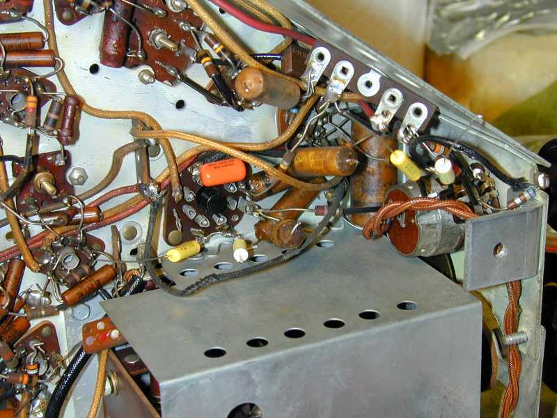
The only tricky area under the chassis is in this corner, where a bunch
of caps are clustered tightly with other components. Here, I have disconnected
some of the old paper caps and begun connecting their replacements.
Again, when dealing with a tangle like this, I often make a sketch,
even if I already have a good parts layout diagram such as the one in the RCA service manual.
It takes only a few minutes, and the last thing you want is to reconnect
everything, then discover that you miswired something at the bottom
of the dogpile!
In addition to paper capacitors, I replaced four 270pf mica capacitors
(C116, C123, C128, and C134) which serve as coupling capacitors in the
picture IF section. Mica capacitors are usually more
reliable than paper ones, but an experienced TV restorer told me that these
can be troublesome, so out they went.
Replacing Resistors
With recapping complete, I made some basic voltage checks and
discovered that we
weren't getting the desired voltages everywhere in the receiver.
Time for a resistor hunt!
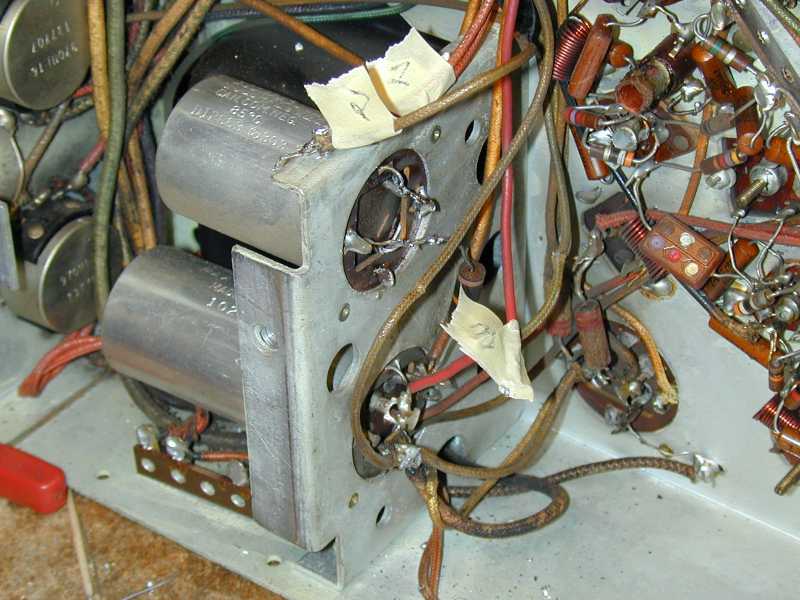
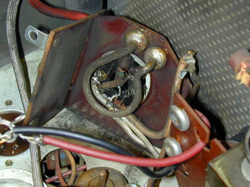
Inside the bleeder resistor compartment, I saw a large, two-section resistor
(R185A/R185B). This is part of a network
that supplies B+ voltages to the entire receiver.
One of its sections had failed completely.
In this photo, I have removed and tagged the leads,
prior to replacing it.
Although it was
manufactured in a single package, the two parts are not connected electrically.
The values of the two sections are also somewhat odd, 1360 and 240 ohms,
respectively.
To replace the higher section, I found a ceramic power resistor
with a slider that could be adjusted to get exactly 1360 ohms. To replace
the lower section, I connected two smaller power resistors in series to make
up 240 ohms. The result doesn't look like the original, but it works just fine.
Mounted lower in the compartment is a flat multi-section resistor. It checked
out OK, so I left it alone.
On the next try, the voltages looked good and the CRT lit up brightly. But after a couple of seconds,
I heard a deadly spitting noise from the high-voltage cage and quickly powered down.
The culprit was a burned resistor tucked under the socket of the high-voltage rectifier tube,
which is mounted on a little phenolic platform standing above other components inside the high-voltage
cage. It took two or three brief power-ups in a completely darkened room before I could
tell where the arcs were coming from.
It took some careful disassembly to reach the resistors buried under that little
platform, but in time the work was done and the area was cleaned up.


High-voltage components tend to attract a sooty dust all over the area,
which is easily cleaned up with denatured alcohol, paper towels,
and Q-tips to reach into the nooks and crannies. I don't think the soot
does any great harm, but my theory is that it's like pushing the refrigerator
away from the wall to clean out the dust bunnies. As long as you've gone
that far, you might as well wash the wall, too!
In the previous photos, notice the round, tan "doorknob" style
ceramic capacitor with the thick copper terminal. Used in high-voltage
circuits of the time, these are extremely reliable. I have never needed to
replace one.
I then checked every resistor 1 megohm and higher in value, and replaced those
whose values had drifted more than 20% from the correct value. High-ohm
carbon resistors tend to change value more than small ones.
Finally, I replaced a handful of resistors whose cases had cracked, as
well as a couple whose leads were pushed through a terminal hole but not
soldered on! These looked like replacements. I guess the serviceman was
in too big a hurry to finish the solder joint.
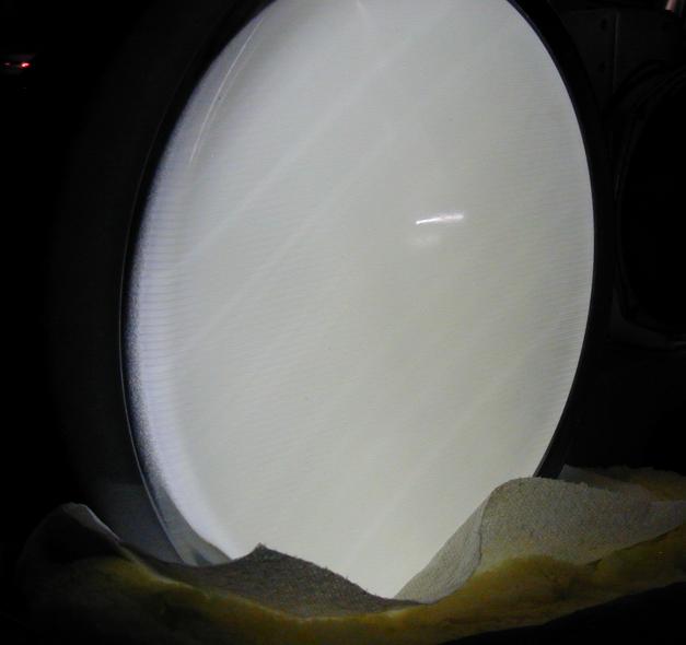
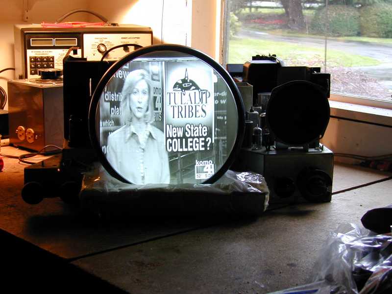
Houston, We Have a Picture!
The next power-up was very gratifying. A decent picture for the first time!
This is a Seattle TV station, received on a rabbit-ear antenna.

Notice how the picture tube is supported in the previous photo. I carved a piece
of stiff foam to support the front of the tube from underneath, covering it
with plastic tape to keep bits of foam from flying onto the tube from static
electricity.
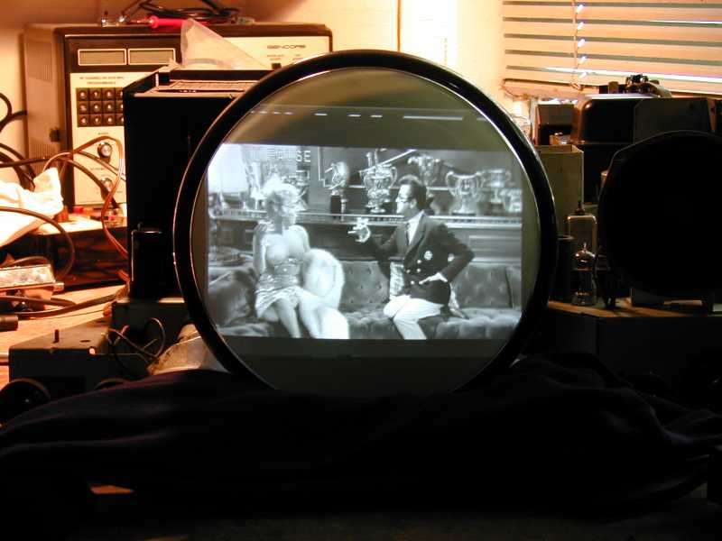
After adjusting various picture controls, the picture was closer to the right
size needed to fit the CRT mask when installed in the cabinet. Here we are looking
at "Some Like It Hot," with
Marilyn Monroe and Tony Curtis.
When Sound and Picture Don't Match
At this point, I had a working television, whose picture I could adjust for excellent
quality, even using my second-best 10BP4 picture tube. Great progress!
The sound, however, left much to be desired. When the TV was fine-tuned for best picture,
the sound on various channels ranged from mediocre to complete silence.
When fine-tuned for best sound, the picture on some channels would disappear.
One weakness of a split-sound audio system is that the IF strips for the audio
and video sections can fall out of alignment with one another, primarily due
to component aging.
Sometimes the divergence between audio and video can be fixed by tweaking
the audio alone.
If you are experienced with radio alignment, aligning the audio section
is no big deal, since it is akin to a simple FM radio.
Aligning the TV's IF section is trickier and it requires additional specialized equipment.
Lacking that equipment and expertise, I brought the TV to a fellow collector and
retired TV/radio repairman who lives nearby. He aligned the television from front to back,
returning it to me in wonderful working order.
Putting It Back Together
At long last, it's time to put the restored TV back into its cabinet.

I would normally do this sort of thing in the workshop, but this thing is
so heavy that I wanted to assemble it within easy carrying distance of
where it was to end up.
For this special TV, I am using the brand-new 10BP4 picture tube which I got
as a spare when I bought my Hallicrafters T-67.
The CRT that came with this set is usable, but not quite as bright. I'll
keep it around as a spare and for testing purposes.
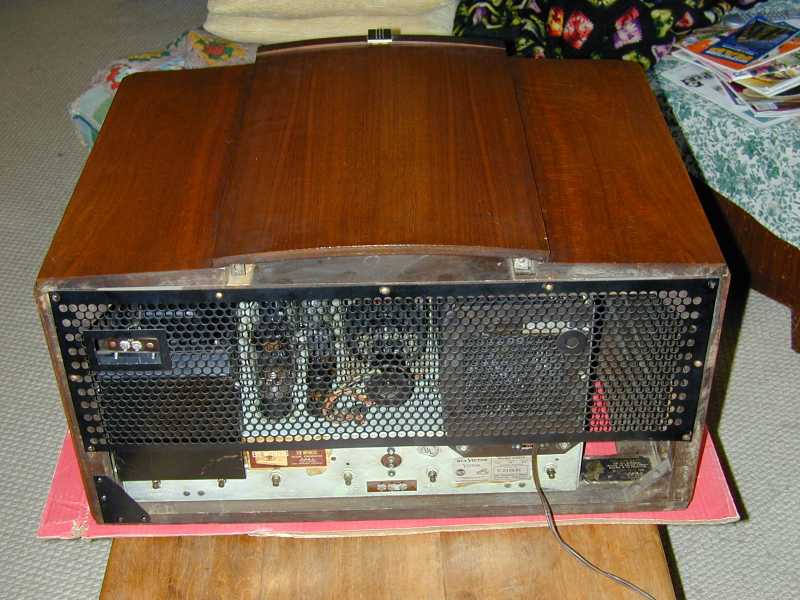
Mustn't forget the back panel. Notice the little triangular metal
brace at the lower left. It must be removed when removing or replacing
the chassis.

It's a-l-i-v-e!!
Phew! All that's left is to move the TV to its final location and
take a few more photos for this article.
Final Thoughts
This was a very satisfying project. I was lucky to start with a
one-owner TV that had not been abused. The restoration took many
hours, but I did not have to deal with catastrophic failures, such
as a burned flyback transformer.
Patience is vital when you're working on an old TV. Notice that the
problem with arcing in the high-voltage cage couldn't be detected
until I had solved more basic problems in the power supply.
This is a pretty typical experience. Fix one problem, then you may
uncover others.
Even a genius won't be able to detect all of
a TV's problems instantly and fix them in one fell swoop. Any sixty-year old tube device
will have a multitude of little problems—most notably,
loads of bad capacitors—as well as a few more serious issues.
If you fix only the serious problems, you may have a TV that works, sort
of, but it will not be safe and reliable to use over the long run.
I always begin with the power supply, since diagnosing other issues
is impossible until you have correct voltages throughout the receiver.
Replace the electrolytics first, unless you want to risk destroying your power
transformer or some other expensive part.
The next step is to perform basic voltage checks and track down
the source of any anomalies.
It's important to know what not to replace. Some TV circuits operate
at very high frequencies, and the values of certain components are critical.
Although I routinely "shotgun" paper capacitors, I leave
mica capacitors (and associated resistors) alone unless I have a specific reason
to think that one is bad. If you replace every resistor in an old TV, you are
wasting a lot of time and laying yourself open to making wiring mistakes, damaging
old terminals or hair-thin coil connections, and so on.
The most finicky parts of any old TV are the vertical and horizontal circuits. If
you replace things willy-nilly in those circuits, without paying attention
to exact values, don't be surprised if your picture degrades in a flash.
Note that many old TVs will not require realignment, unless
someone previously messed things up by twiddling adjustment screws at
random, without the proper equipment. I have restored several early TVs, and this is
the only one which needed a full alignment to become usable.
I believe in taking notes as I go through a project. In this one, every time
I replaced any component, I marked it off in three places: the schematic, the parts
layout diagram, and the factory parts list.
If you take notes as you go, you won't have to rely on your memory for everything.
If you are tackling a TV restoration for the first time, be aware that
televisions produce much higher voltages than any tube radio. The
thousands of volts supplied to the picture tube can knock you across the
workshop. Use great caution when doing any
tests on a powered-up chassis and follow the old-timer's rule
of keeping one hand in your pocket.
I would not recommend a 630TS as a first TV project. Although it's one
of the best-performing early televisions, it's also quite complex. Later
TVs have fewer tubes and fewer components overall, meaning fewer things
to replace and fewer places where trouble may arise. You would
be better off finding an inexpensive mid- to late-1950s B/W tabletop and
cutting your teeth (i.e., making your first mistakes!) on that project.
Finally, I'd like to say thanks to people in the following online forums for their
helpful advice and encouragement in this project: the
rec.antiques.radio+phono newsgroup, AudioKarma,
and Antique Radios.
You know who you are, guys! And a special hats-off to Bob Meader for aligning this TV.
What's Next?
Just as I was finishing this project, I acquired a "roundie," or early color TV with a round
21-inch picture tube: an RCA CTC-11.
I had to make a long drive to pick it up, but the owner was willing to
trade it for a little old Scott audio amp that I had bought
for $7 about ten years earlier.
The cabinet needed work and it was missing a couple of knobs, but it
had an almost-new picture tube and the price was right. I was soon to learn
that color TVs are much more complex than black and white sets. Oh, well—out
of the frying pan, into the fire! Here is the CTC-11 before and after
restoration.

|