RCA Model CTC-11H Color Television (1961)


Shortly after restoring the electronics on my first
RCA CTC-11 color
television, I ran across a craigslist ad that said, "Very Old Color TV $1."
To my surprise, it was another CTC-11 in a different cabinet style.
The price was too good to resist, so I brought it home. The owner
probably would have given it away, but I handed him a $5 bill and told him to buy
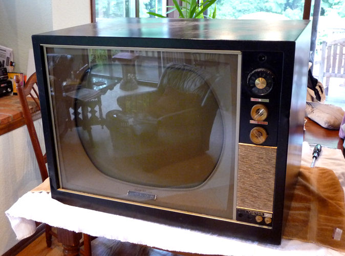
a latte on me. Here is the TV, right after I brought it home.
The cabinet is black painted steel with gold trim. It has short rubber
feet for use as a tabletop, and removable gold wooden legs for standing
on the floor.
RCA produced a dizzying number of CTC-11 variants, with different
cabinets and optional UHF tuners and remote controls. The Sams service
manual lists 43 different CTC-11 model numbers! This chassis is
a CTC-11H.
With a metal cabinet and type KRK98K VHF tuner, this is model 211CB392,
an economy set priced about $100 lower than my other CTC-11 with
wooden console cabinet. The TVs inside are identical.
Electronic Restoration
As with every restoration, I began by testing each tube, cleaning its pins,
and using DeOxit to clean user controls such as the volume. A couple of
small tubes were weak and needed to be replaced. The full
tube lineup is
listed in my other CTC-11 article. The Sams service manual for this TV is
Set 550, Folder 2.
The picture tube looked strong on my Sencore CR70 tester, an
encouraging sign. These CRTs are not cheap to replace. A good
one typically costs about $150-$200.
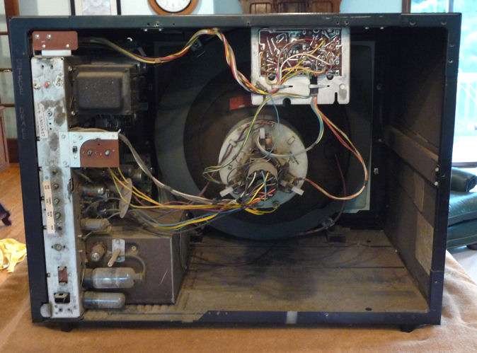
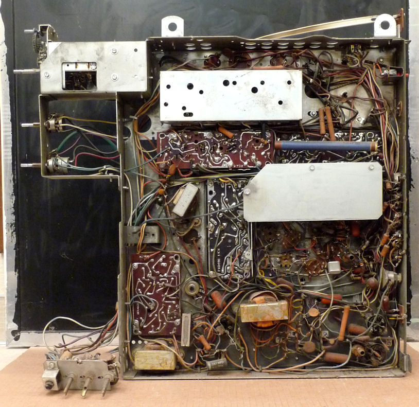
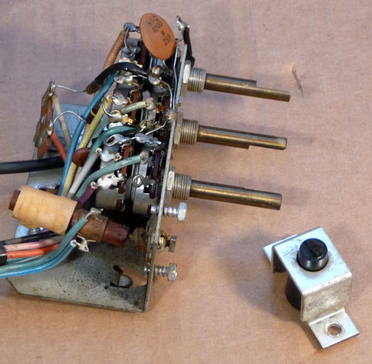
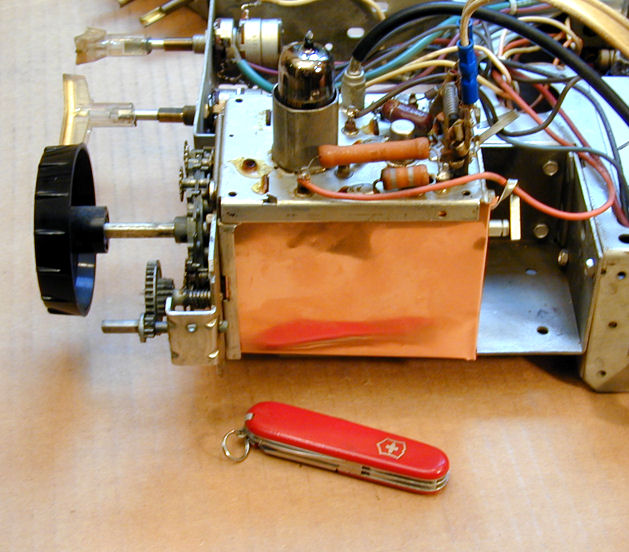
Here is a look beneath the unrestored chassis.
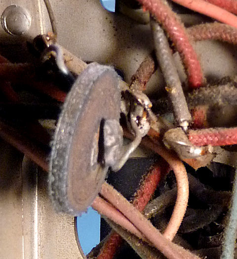
One problem jumped out. The horizontal hold control, leftmost
in this view of the little control subchassis, had been broken in a moving
accident. The plastic shaft was snapped off, the control had been pushed
back from the subchassis, and (I would later learn) the thin threaded
stem that moves the ferrite core inside the coil was bent.

I made a note to fix that later.
No Power
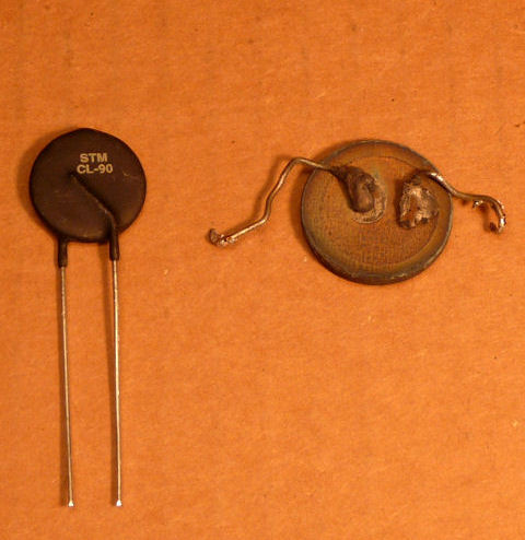
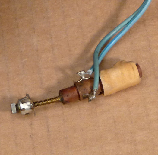
The television was completely dead. The obvious cause was
a bad thermistor in the power supply. Notice how one lead has popped loose.

A broken thermistor like this one blocks all power to the TV. Its purpose
is to prevent a sudden power surge when you switch on the TV. Its resistance
decreases when it warms up, providing a "soft start"
to protect other components.
The second photo shows the bad guy next to his replacement, a new type CL-90.
When I unsoldered the old thermistor's legs from the TV's terminals, they simply
fell off. It might be possible to reattach these, but when a replacement
costs only a buck, I treat myself to a fresh part.
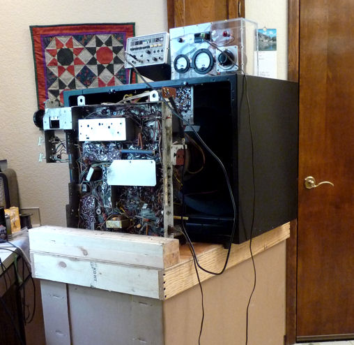
Time for the maiden flight. I put the chassis behind the cabinet on
a sturdy box and reconnected everything. This lets you test
voltages under the chassis while the set is powered. On top are my TV pattern generator at
left and my metered variac at right.
Bringing up the power slowly, with an eye on the variac's meter, I saw
the set come to life. Knowing the horizontal hold control was broken, it
was no surprise to see bad horizontal lock. But there was a visible
picture—Wahoo!—albeit a very dim one.
The good news was that the TV was basically functional, not making any
fireworks or evil sounds. I made a few quick voltage checks and powered the set down.
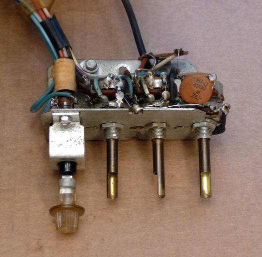
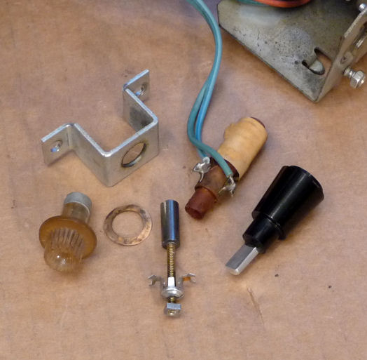
We Control the Horizontal
You can't evaluate a picture that's a blizzard of slanted lines, so
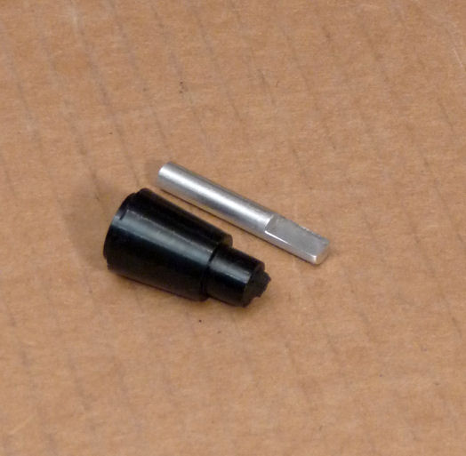
the next step was to fix the horizontal hold control. I needed to replace the broken
shaft end with a half-round piece for the knob to slide onto, then
straighten the bent stem for the ferrite core.
To make the new shaft end, I cut the end off a surplus potentiometer
with a round shaft and filed it half-flat. Then I filed the broken stub
from the larger black plastic shaft portion and attached the new flat end
with epoxy. This was tedious to do with a hacksaw and
hand file, but I don't have good metalworking tools.


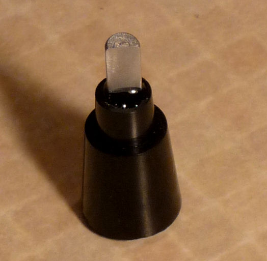
I used a lot of caution when straightening the threaded stem. If I
broke the ferrite core, the control would be useless. It's still not
perfectly straight, but it was close enough to reassemble the control
and make it work.


I later learned that this TV's horizontal lock is extremely stable, so
with luck I shouldn't have to use this control very often. Now all
I need is two new knobs of this type to replace the ones that were
broken in the moving accident. If you have clear knobs like this,
send me an email.
Chroma, Yes — Luminance, No
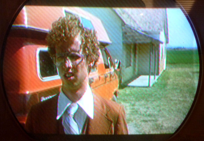
Now I was ready to reassess the TV's picture.
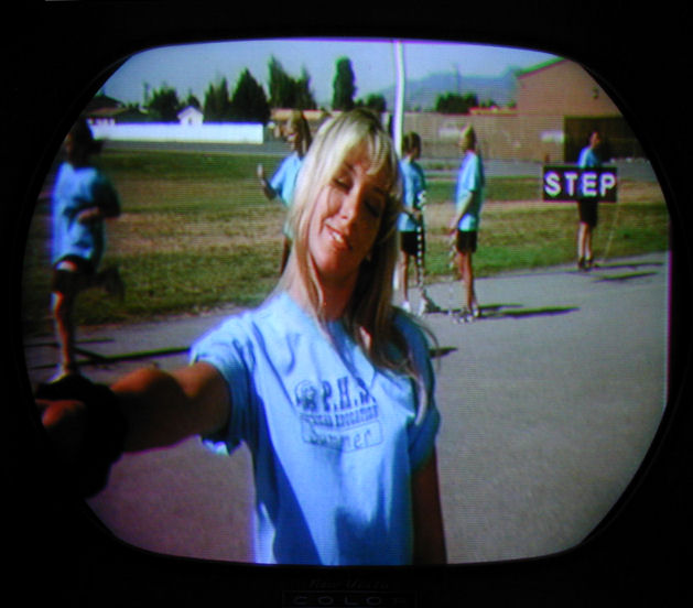
The initial result was puzzling. On the left is this TV's screen. On
the right is my restored CTC-11 displaying the same image.

Many aspects of the "bad" picture are hunkey-dorey. It has excellent
horizontal and vertical lock. Screen geometry is good. There are no major
problems with convergence or purity. Detail and focus are acceptable, and
it looks like the right colors are trying to display in the right places.
But why was the picture so dim? I could change colors with the color controls,
but the brightness and contrast controls had no effect.
I posed the question to a vintage color TV forum, and Bill Sheppard
suggested that the set was displaying the
correct chroma (color) information but lacking the
luminance part of the signal (i.e., the "black and white" brightness
and contrast).
This led me to investigate the video amplifier/output PC board,
which contains two tubes: type 6AW8A for amplification and 12BY7A for
output. Those tubes are connected to the TV's brightness and contrast
controls, respectively.
Checking them under power, I discovered that the
voltage on pin 8 of the amp tube was much too high, almost twice the
specified 120 volts. Something fishy in Denmark.
I checked resistors and capacitors on the board, replacing one tiny
electrolytic capacitor because it was easy to reach and old electrolytics
often go bad. Other components, including the tubes themselves, tested
well within limits, yet the problem persisted.
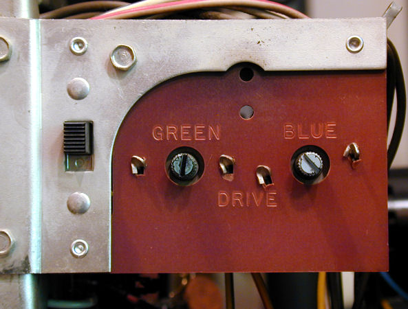
Various ideas were tossed out, until Bill asked whether the TV's service
switch might be dirty. Used only when making video adjustments such as
gray scale, it's an unobtrusive little slide switch in back of the chassis,
next to the blue and green drive adjusters.
I shot a bit of DeOxit into the switch and worked it up and down
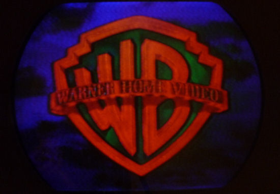
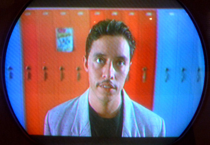
several times, then waited for the cleaner to dry. When I powered
the TV back up, I was rewarded with these pictures. (Ignore the herringbone
effect in the photos; the cheap DVD player in my workshop puts out
a lot of RF interference.)

What We Learned in Class Today
Problem solved! If I had thought to clean that little switch in the beginning,
along with all the controls and tube pins, I would have avoided this
problem entirely. Don't forget to clean the service switch if you run
across one.
Although perhaps unnecessary, this detour taught me a little more about this
TV, and even some incorrect hypotheses were interesting. For example, someone
suggested checking the delay line. "The delay what?" I asked.
A component I hadn't yet learned about, the delay line is a timing device.
On this set, it's a cigar-shaped tube, wound with wire, mounted behind
the video PC board and stamped March 18, 1961. Notice the long blue
component in our chassis photo.
To quote my RCA Color TV Service Manual, "The basic function
of any delay line is to slow down the video so it arrives at the picture
at the same time (same place on the screen) as the chroma signal. A wrong
'size' or defective delay line causes the B & W video to appear at
the left or right of the chroma picture."
And so on, the gist being that a delay line defect
can separate the chroma and luminance, with a
result that's similar, although not identical, to the
symptom I had seen.
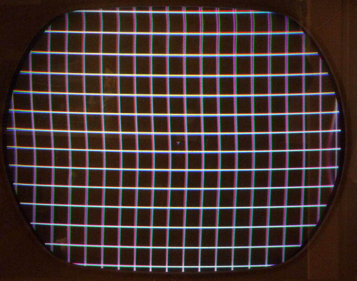
And Now For Some Exciting Test Patterns!
Now I could use the pattern generator for a more scientific look at the picture.


Not too shabby for a 48-year old TV that's still about 98% unrestored.
The color bars are bright. The crosshatch pattern shows slight misconvergence, with red
vertical lines offset from the green and blue lines. However, the
lines are nicely squared off rather than bent, and it shouldn't take much work
to converge the picture tube's electron beams so that all of the lines are
an even white.
If you read the saga of my other CTC-11,
you'll learn that convergence is not always so easy. On that TV, I spent many
hours fiddling with adjustments and rebuilding half of a PC
board before I could get convergence as good as this.
Look at the right edge of this crosshatch pattern, and you'll see
a snaky curved line. It moves slowly up and down, making the other vertical
lines "breathe" slightly to the horizontal in the same rhythym.
This is ripple from the power supply, which should clear up after I replace
the remaining twelve electrolytic capacitors.
Although I had completed initial "make it work" repairs, installing fresh
electrolytics is vital for safety and reliability. See my other CTC-11 article
for details.
A Tale of Two Tuners
The TV's tuner also left much to be desired. It was either very worn
or very dirty—or both. Clicking the tuner knob into
a regular channel position produced nothing but a snowy screen and
static from the speaker.
I could only tune in a station by carefully
nudging the tuner into a position between two channels.
For instance, to receive channel 5, I had to turn the selector about halfway
between 4 and 5.
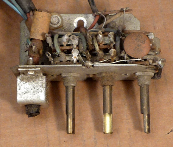
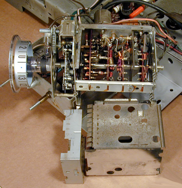
At left is a first peek into the tuner for this TV. Contrast this photo with
the second, which shows the tuner for my restored CTC-11.


Missing from this tuner are its protective shields, shown removed
from the tuner in the second photo. These keep dirt
out of the delicate mechanism and block RF interference
like the herringbone pattern seen before.
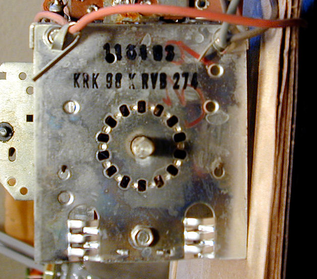
To clean the CTC-11 tuner, you need to unbolt it from the chassis. Unplug
the RF cable and antenna connectors, but leave the other leads attached.
This lets you turn the tuner around and upside down.
Freeing the also tuner reveals the version: KRK98K in this case,
which makes this television a CTC-11H.
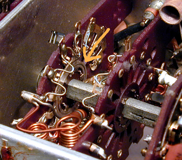
I initially tried to clean the tuner by carefully spraying
the contacts with DeOxit and then turning through all of the
channels several times. I have used this method to clean many
radio bandswitches, but it was useless in this case.
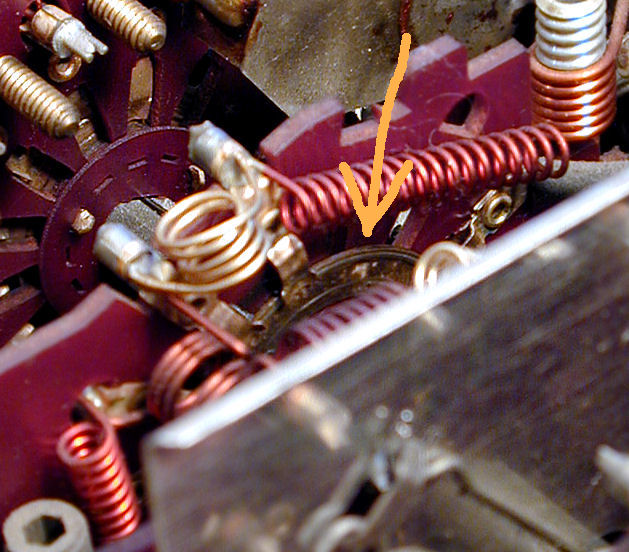
Here is the tuner after spray cleaning. Notice how much dirt remains on
the contact marked with an arrow. It is dark brown with accumulated grime.

Time to get serious. I spent the next couple of hours carefully
hand cleaning every contact in the tuner, using Q-tips dipped in
DeOxit. Where the space was too tight, I tore most of the fluff
from the Q-tip head and wrapped the remaining fibers tightly around
the stick. This required a lot of patience. I also used a strong
light with a large magnifying lens.
The contacts eventually cleared up. Here is the same
switch wafer after cleaning, seen from the other side of the tuner.
The round portion has some scoring but it will make good
electrical contact.
Next, I cleaned the entire tuner inside and out with alcohol to remove
any lingering traces of DeOxit from my unsuccessful spraying attempt.
Finally, I went back over all of the contacts with an electronic
conditioner and lubricant.
The front mechanism outside the tuner cage was cleaned
and relubricated with a sparing amount of grease. I also tightened
a little setscrew on the main shaft to eliminate slop in the tuner
action.
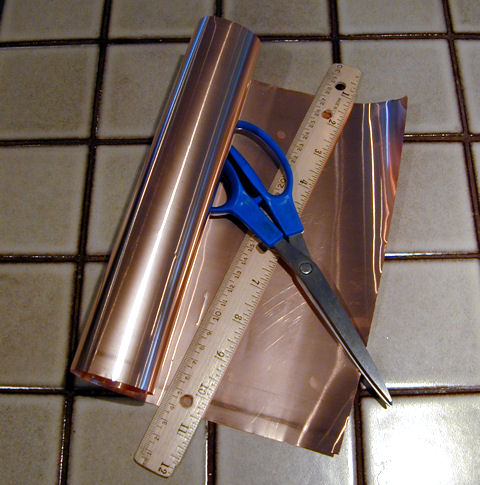
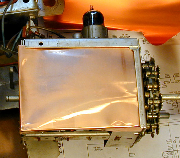
The TV still lacks shields. My chance of finding original parts is slim,
so I made simple replacements out of heavy copper foil from a craft store.


Cleaning made a big difference. The picture looks better than ever and
the fine tuner works, as well.
Replacing Electrolytics is Easy and Fun!
Well, not really. This television has 13 electrolytic capacitors.
Nine of them are housed in three cans in a row atop the
chassis. I replaced all of 'em in a marathon session. It's a
tight squeeze to mount all nine electrolytics in the narrow channel
underneath, but I didn't have the patience to "restuff"
the old cans, and the TV works the same either way.
Now the TV operates nicely, without a trace of the power ripple that
I noticed in an earlier test pattern. The picture looks even stronger
and I'm confident about playing it for long periods. The article for my other CTC-11 has more information about recapping, if you're interested.
Final Thoughts
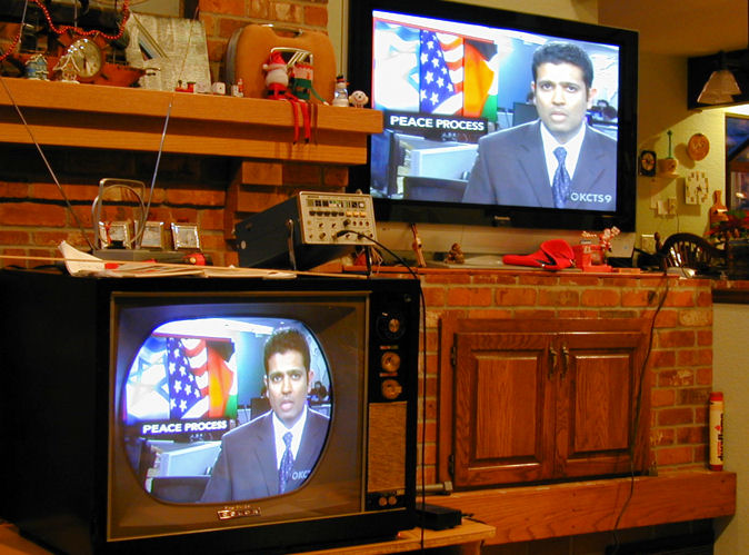
To finish up, I repeated the entire setup process, starting by degaussing the
picture tube and setting the grayscale, then adjusting the purity and
convergence. Here's the CTC-11A playing in our family room, with a
plasma TV in the background for comparison.
The picture quality is outstanding and the colors are quite accurate.
(Both pictures are a little washed out because I have the brightness
set for daylight.)
It's hard to overemphasize the importance of doing careful setup for
a color TV. If you simply replace capacitors, you may get a set that
shows lots of colors, but isn't accurate enough to enjoy in everyday
viewing. An excellent book is the RCA Color Television Pict-O-Guide,
widely available in the used book market. It details these procedures,
with plenty of color illustrations and theory. I have two editions,
from 1957 and 1964. The 1964 edition is more useful for this
particular model.
While I was sporadically working on this TV, I ran across two 1940s black
and white bargains: an RCA T-100 tabletop and a DuMont RA-103 in
a "Meadowbrook" console cabinet. Each of them
cost $40. The DuMont even came with schematics and a box containing
39 good tubes. You can read about them by clicking on the icons below.

A couple of years later, I came across an RCA CTC-7 that I couldn't resist.
It was made a few years earlier than the CTC-11 and it's interesting to
compare the two.

A couple of years after restoring this television, I was experiencing a
space crisis and sold this set to a fellow collector
in Canada. He had more room than I do, and you can't keep 'em all!
|