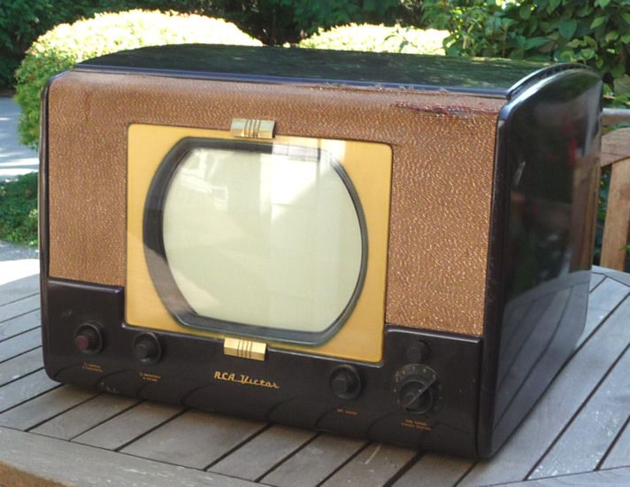
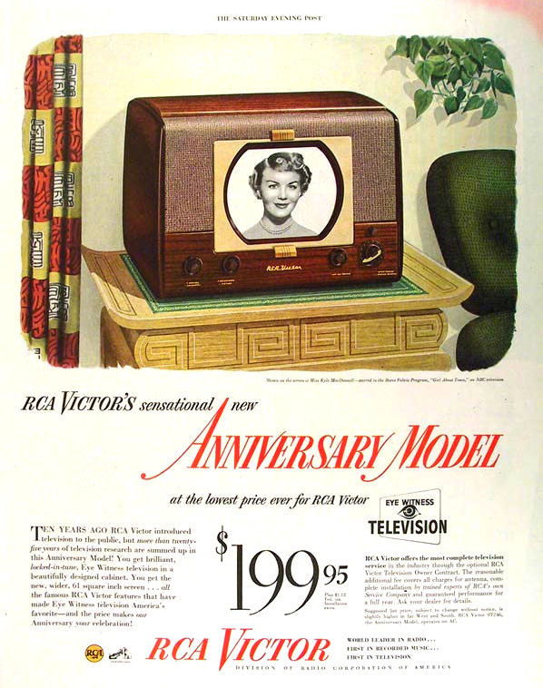
RCA Model T-100 Television (1950)


This RCA model T-100 television from 1950 sports a classic postwar
design. Sleek cabinet, proven electronics, and a "big"
10-inch screen . . . what's not to like?

I had promised not to buy any more vintage TVs until I finished
my CTC-11C color "roundie,"
but this one was too cheap to resist.
Up From the Depths
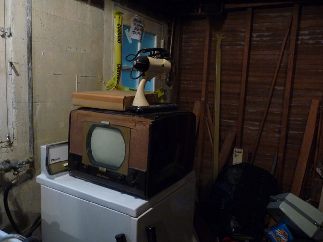
My first sight of the TV at an estate sale was depressing. It sat
on a washing machine in a dark basement, covered with dust. The
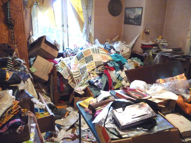
house was incredibly messy, as the second photo shows.


The TV was priced at $160, much too high in my view, so I decided
to return the next day. On the way out, I noticed a filthy little TV on
top of some trash bags by the garage. I asked the estate sale boss if I could take
it. He grumbled and said, Yes, if you promise not to dig through any more garbage!
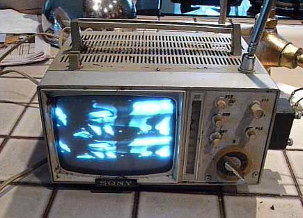
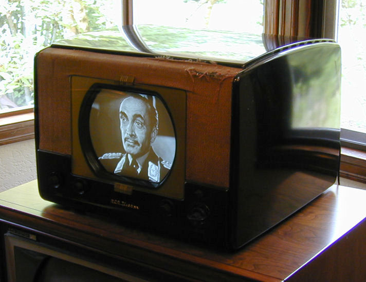
The rejected TV looked so forlorn in the rain that I couldn't
bear to leave this wounded soldier behind. I let it dry out overnight, then
powered it up on a variac. To my surprise, it almost worked.

OK, it has a few problems, but I'm betting I can fix them.
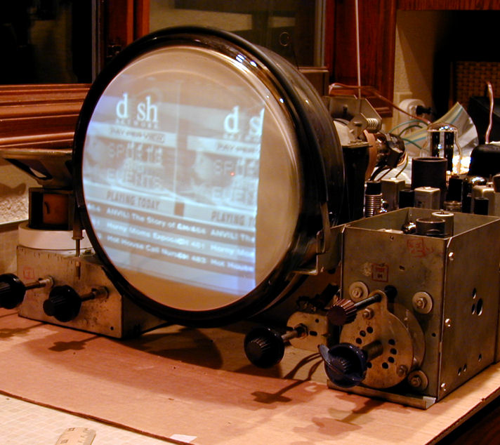
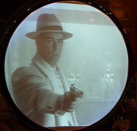
That's President Obama discussing health care reform on a Sunday news
show. The set is receiving the signal through its own antenna. I have
a home TV transmitter that I feed from our satellite dish.
First Look
Back to the T-100, it was still on the washing machine when I returned
the next day. We struck a deal for $40. After scrabbling around,
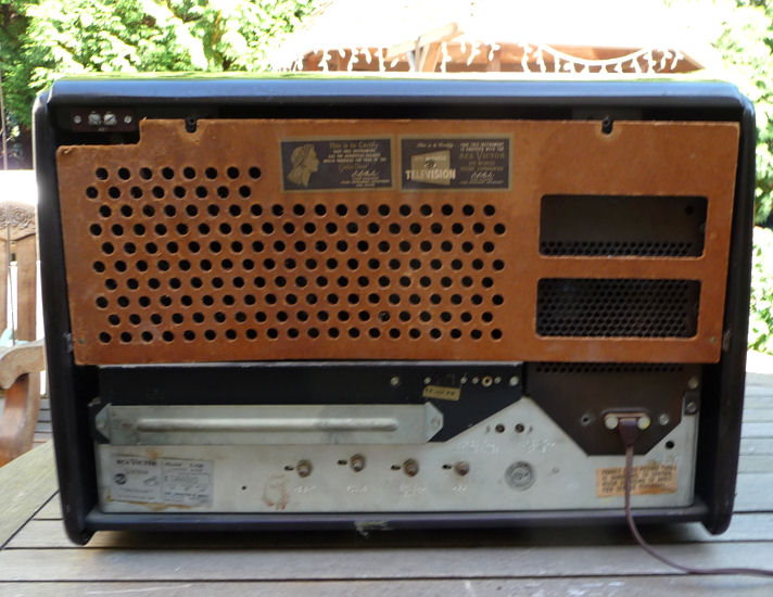
I found the TV's back cover in a pile of stuff on the floor.
I talked to the house's owner at the sale. He was a child
when the family bought the house in 1950, and remembered
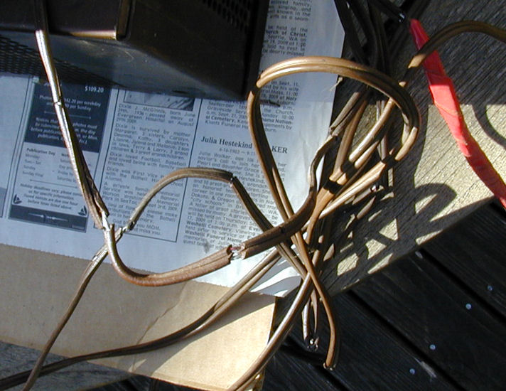
this as their first television. Here it is on the deck,
right after I brought it home.
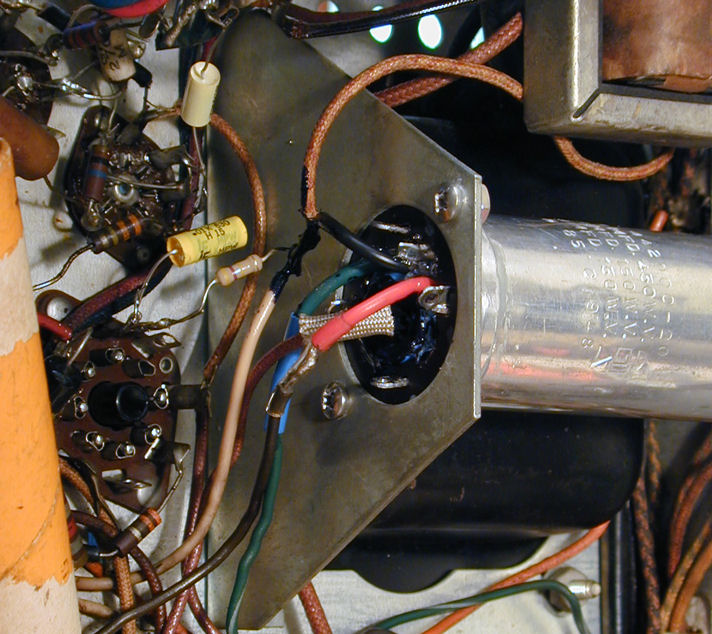
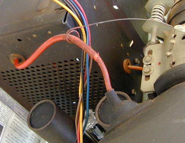
Some problems are impossible to miss. Look at the ruined power cord. Something
tells me the TV hasn't played in long time. The red high-voltage cable to
the picture tube was damaged by sparks arcing through its insulation.
A springy wire support provided a convenient discharge path
for nine thousand volts! In the second photo, I have slid the
support away from the spot where sparks had chewed through
the insulation.


Before doing anything else, I replaced the power
cord and painted the CRT cable with corona dope, an
insulator for high-voltage components. I may eventually install a new
cable, but the dope will do for now.
Electronic Design
The T-100 was produced four years later than my RCA model
630TS, evolving
from that classic electronic design. Among other things,
it uses 24 tubes rather than 30 and it features automatic, rather
than manual, gain control.
Both TVs use a 10-inch 10BP4 picture tube. Here's the complete
T-100 tube lineup.
| Tube |
Type |
Function |
| V1 |
6AG5 |
RF amplifier |
| V2 |
6AG5 |
Mixer |
| V3 |
6J6 |
Oscillator |
| V4 |
6BA6 |
1st video IF amplifier |
| V5 |
6AG5 |
2nd video IF amplifier |
| V6 |
6BA6 |
3rd video IF amplifier |
| V7 |
6AG5 |
4th video IF amplifier |
| V8 |
6AL5 |
Video detector / Sync limiter |
| V9 |
12AU7 |
Video amplifier |
| V10 |
6AU6 |
1st audio IF amplifier |
| V11 |
6AU6 |
2nd audio IF amplifier |
| V12 |
6AL5 |
Discriminator |
| V13 |
6AV6 |
Audio amplifier |
| V14 |
6K6GT |
Audio output |
| V15 |
6SN7GT |
AGC amp/Vert osc/Vert disch. |
| V16 |
6SN7GT |
AGC rect/1st sync separator |
| V17 |
6SN7GT |
Sync amp/2nd sync separator |
| V18 |
6K6GT |
Vertical output |
| V19 |
6SN7GT |
Horiz AFC / Horiz Oscillator |
| V20 |
6BG6G |
Horizontal output |
| V21 |
6W4GT |
Damper |
| V22 |
1B3GT |
High voltage rectifier |
| V23 |
5U4G |
Low voltage rectifier |
| V24 |
10BP4 |
Kinescope |
This chassis was offered in almost a dozen tabletop and console cabinets,
using 10-inch or 12-inch picture tubes. My chassis is type KCS38. Here is the Sams service manual
(Set 93, Folder 9); to download it, right-click the icon and choose Save Target As:
Like the 630TS, this TV has a "split sound" audio system, meaning
that the sound signal is picked off midway through the video IF amplification
process and put through its own IF amplification. Later designs simplified this
parallel-IF scheme, to reduce the overall parts count and somewhat simplify
troubleshooting. Although my T-100 never showed this problem, in some split-sound
sets the best audio quality doesn't match up with best picture when tuning.
Checking Tubes
An initial step in every restoration is to check every tube and
clean its pins. At this time, I also clean the controls (volume, etc.)
with DeOxit spray. Two of the small tubes were missing, so I replaced
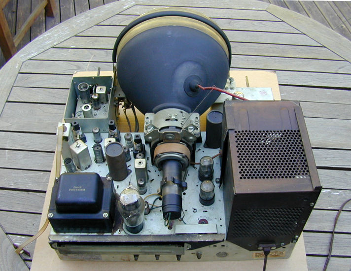
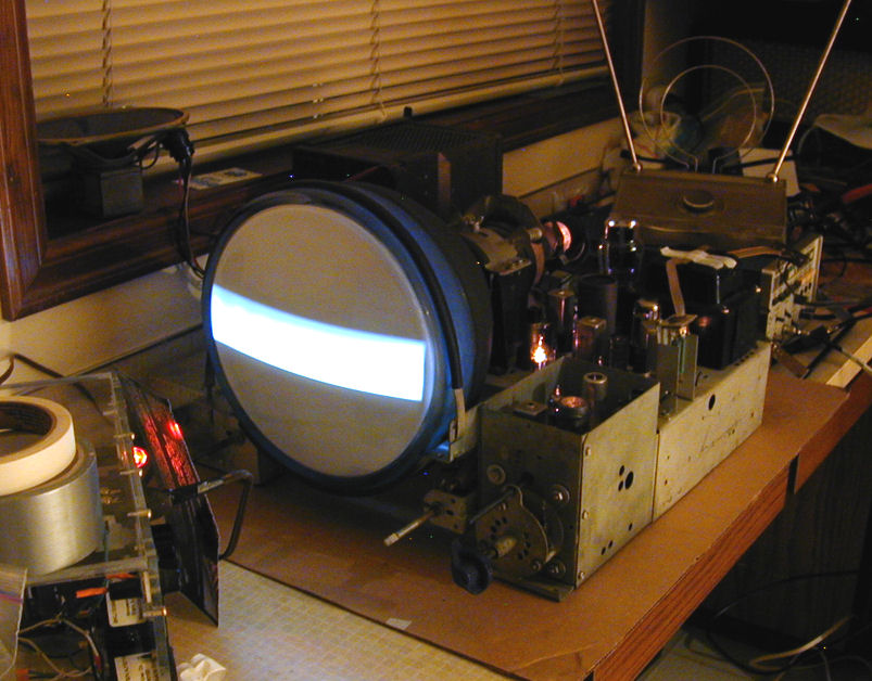
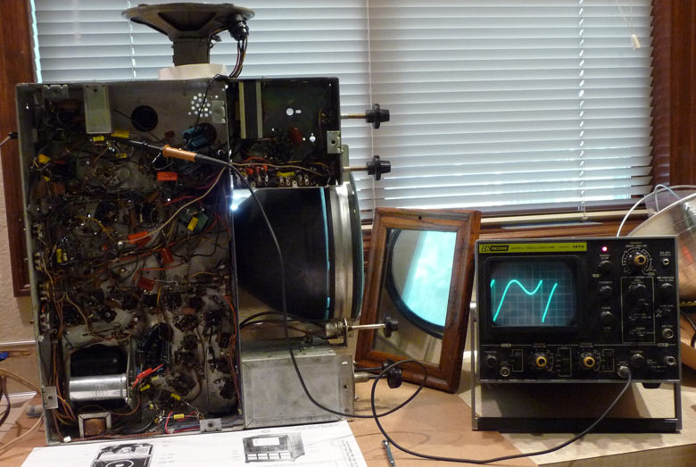
them. The picture tube looked feeble on my Sencore CR70 tester, showing
close to zero emission. That's the CR70 next to the TV chassis in
the next photo. It's sitting on top of my pattern generator, waiting
for the first time I power up the set.
Increasing the filament voltage from the standard 6.3 volts
to 7 volts resulted in somewhat better emission, so I left the
picture tube to "cook" at that voltage overnight. My
CR70 also has rejuvenation capability, but I didn't feel like
messing with that at the time. A spare 10BP4 picture tube was
sitting in the workshop if I needed it.
The next day, I cautiously powered up the TV for the first
time, keeping a watchful eye on the meter in my variac.
After a little fiddling, I was gratified to see the
screen light up.
Everything else about the TV was poor. No sound, no
signal on the blank screen, no hint of vertical or horizontal
sync lines, and the dim bar of light was visible only in a dark
room.
Such things are to be expected in an unrestored 60-year old television,
of course.
On the positive side, I could see that the TV should not be impossible
to restore. The power transformer and flyback transformer were not
toasted, and quite a few things have to be working reasonably well
to display even a faint image like this.
Capacitors, Capacitors
The whys and hows of replacing capacitors
are covered elsewhere on this website, so I'll just hit some
highlights.
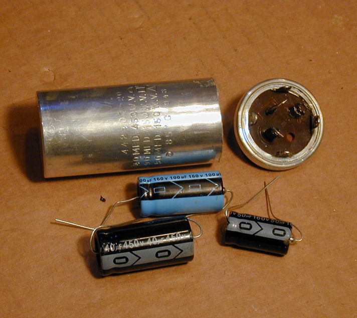
This television has 13 electrolytic capacitors contained in
four multi-section cans, three cans with three caps apiece,
and one can with four.
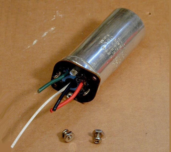
One of the cans is mounted under the chassis.
I "restuffed" it with three new capacitors.


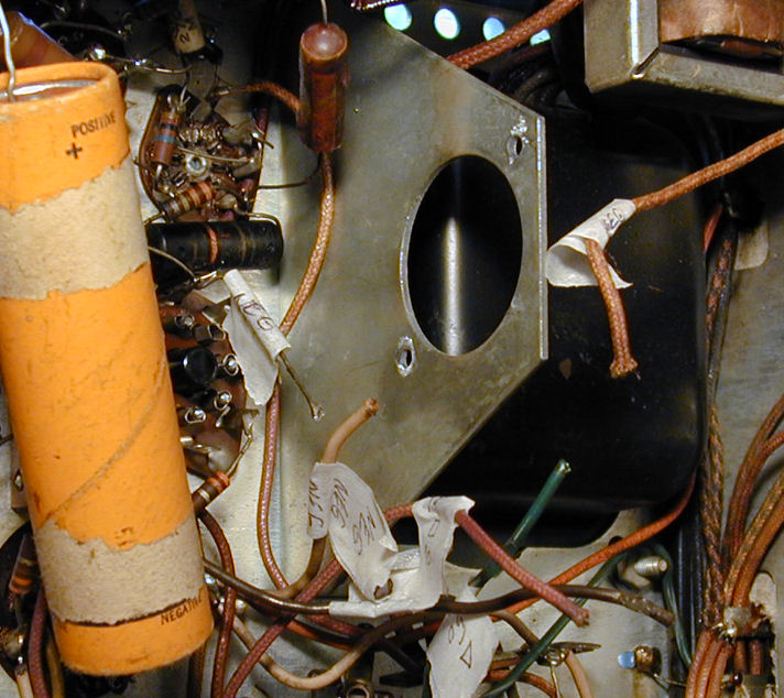
For this job, I often label the disconnected wires with tags.
Drawing a sketch of the connections is another
good practice. If you're interrupted partway through the task,
you may not remember how everything goes back together.
The new capacitors were a bit too large to fit perfectly in
the can, but I made things work. Capacitors with radial leads
are usually smaller than ones with axial leads like these.
Although the result isn't as beautiful as some restuffing jobs I've
done, the caps work properly and I didn't clutter up the
area, which would have made other components hard to reach.
Notice how I also replaced two small capacitors and a
resistor while I was in the neighborhood.
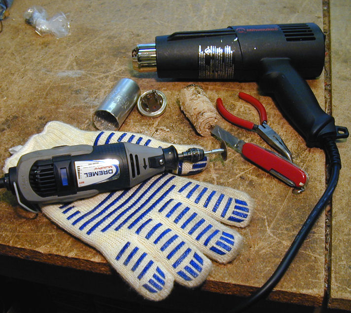
If you're wondering why old electrolytics go bad, look
again at this photo showing how I removed the innards.
See the little pile of dust above the oven glove? That's dried
electrolytic paste, which fell out when I removed the innards. In a
good electrolytic, the paste will be wet and pliable. In a bad one
like this, it's crusty junk that crumbles at a touch.
There is no way to reliably "re-form" such a capacitor,
although some people try. It's garbage. Replace it.
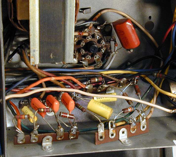
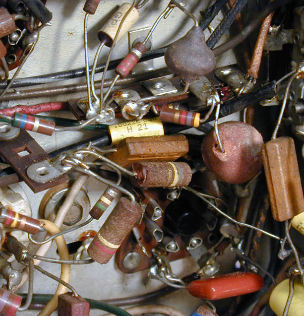
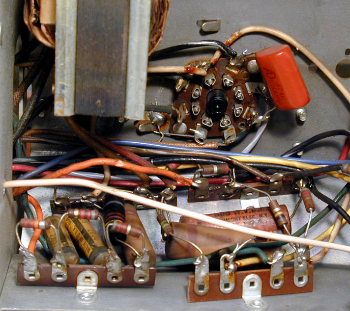
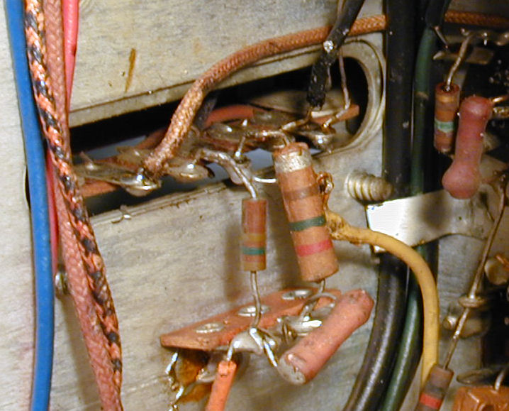
The rest of the recapping was routine. This area near the
vertical output transformer has a cluster of paper capacitors.
Replacing them was easier than it looked at first. Modern
caps are smaller than old ones, so it's easier to fit them
into tight spaces.

First Picture
With new electrolytics in place, it should be reasonably safe
to power up the TV. The original picture tube tested almost
dead, so I subbed a stronger spare from the shop.
The first look was weird. This is a TV with a misadjusted ion trap
and a cockeyed yoke.

The ion trap is a magnet on a circular mount that slips around the neck
of the picture tube. When correctly placed, the picture is bright and
clear. When off the mark, the picture is distorted or completely
dark. After replacing the CRT, I had just guessed about the right position
for the ion trap. My guess wasn't very close.
I hadn't noticed it before, but when checking the yoke adjuster screws,
I found that they were loose. Slipping in the new picture tube evidently
jostled the yoke out of position. Or maybe some past "repairman"
was playing around. As we'll see later, there was also evidence of
monkey business in the tuner. In any case, the yoke issue, together with the
ion trap problem, created the image shown above.
Both conditions were cured in a couple of minutes. The next photo may
look poor, but it's actually encouraging.

Four good points are worth noting. The picture is bright enough to be
seen in normal lighting. The image is rectangular, as it should be.
The image is reasonably centered. Finally, although it's not obvious
from the photo, the vertical hold is functional (there is no
vertical roll).
So much for the good news. The horizontal synchronization was way off,
making a torrent of zigzagging lines.
Adjusting the horizontal hold control was useless.
Loss of horizontal sync often means that the horizontal circuit is not running
at the necessary frequency of 15,750 cycles per second. One of the paper
capacitors that I replaced was connected to the horizontal oscillator
transformer, so tweaking that adjuster seemed a logical place to start.
Not perfect, but better. The picture is stable, although it is
overlapped. The oscillator is running too fast, roughly double
the correct frequency since we see almost two complete images.

In addition to the horizontal frequency, the service manual mentions
adjustments for the horizontal linearity, locking range, horizontal drive,
and width. It would be a mistake to start randomly changing all of those
adjustments without the right equipment in place, but I found that a couple
more very slight tweaks produced a solid picture at last. Hooray!
Time For Midterm Exams!
Despite these positive signs, we're not done by a long shot. Although the
TV is working—sort of—there are several unknowns. Time to give
the set a physical.
Voltage checks around the chassis revealed that the power
supply was basically sound. Several tubes that I checked had voltages
in the right ballpark.
The high-voltage supply was another matter. While trying out the TV during
recapping, I had seen the picture come and go at unpredictable intervals,
sometimes accompanied by the snapping sound of sparks—never a good
sign.
Although I had tested the tubes and carefully cleaned inside the H-V
cage, it's not unknown for "good" tubes to give up the ghost
when given the right voltage for the first time in decades. I rechecked
the HV tubes, which were still good. I also looked carefully for any
telltale signs of HV arcing, finding none.
High voltage is dangerous, but there's a simple test
that tells whether your H-V section is working at all. With the
H-V cage removed, you power up the set, put on a rubber glove,
then carefully extend a screwdriver with a well insulated
handle until its blade is about half an inch away from the
cap on top of the H-V rectifier tube.
A healthy H-V supply will make a fat spark jump from the
tube's cap to the screwdriver blade. You may also hear a
hissing sound. I saw the lucky blue spark,
but still had questions about the funky H-V lead to the
picture tube.
Next, I tested whether high voltage—9,000 volts
in this case—was actually reaching the picture tube. You
can't do this with an ordinary multimeter. I use a Pomona
H-V tester.
I carefully unplugged the lead from the picture tube bell and
taped it to point well away from the chassis. Powering up the
set and wearing rubber gloves, I saw a solid
8,000 volts on the tester.
That's 1,000 volts shy of ideal, but good enough to
light up the CRT while I address other issues.
When replacing paper capacitors, there were two, both rated
for 1,000 volts, with oddball values which I didn't have on hand.
Not surprisingly, they are part of the H-V supply circuit.
I'll retest the H-V level after the new parts arrive in the mail
and I install them.
The AGC (automatic gain control) was also questionable. This
T-100 television is similar to my RCA 630TS,
but differs in having AGC. The 630TS has a "picture control," or
manual gain control, which you adjust to compensate for the
differing strength of signals from various stations. An AGC
circuit does this automatically, as the name implies.
This television showed extreme sensitivity to the strength of
the incoming signal. While testing, I used my home transmitter
setup (which I'll describe in a later article) and a rabbit
ear antenna. This simulates the environment the TV was designed
to operate in, whereas the signal from a modern DVD player or
other source may easily overload the receiver.
To call the AGC twitchy is an understatement. Connecting
or disconnecting the antenna, walking around the room,
touching the antenna terminal with my fingers, or simply
waving a hand near the antenna terminal might make the
picture tube go completely black, or erupt in a wild display
of static, accompanied by snap, crackle, and pop.
Note to self: after dealing with more urgent problems, you
need to thoroughly check out the AGC circuit and set it
to factory specifications.
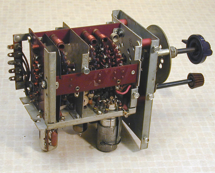
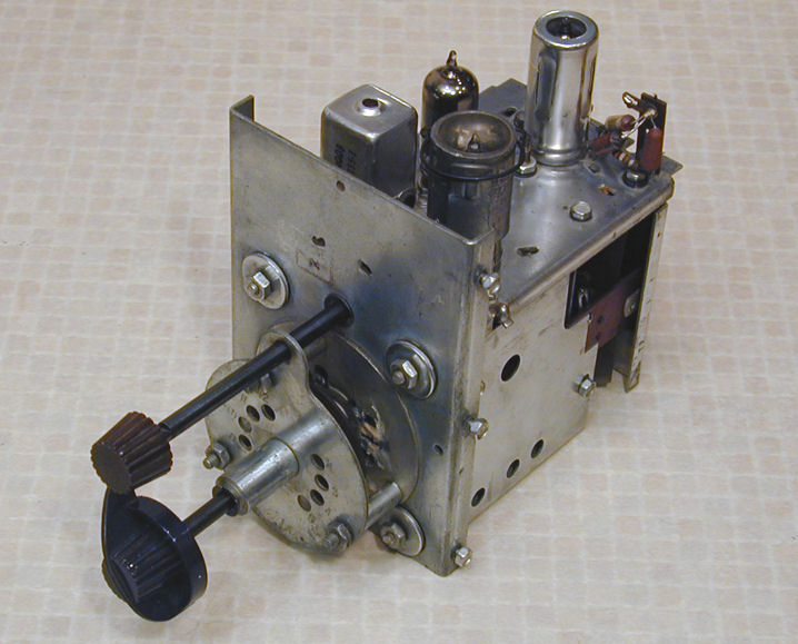
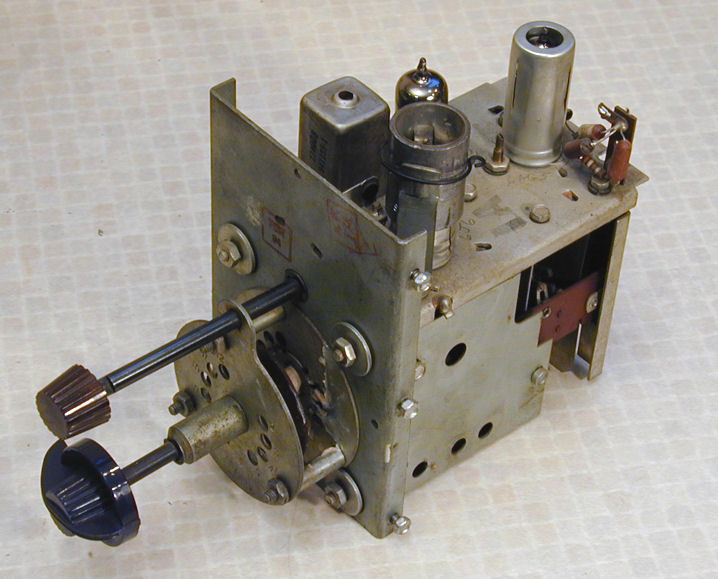
Tuner Disassembly
During every trial of the TV, it was obvious that the tuner needed
serious attention. It wasn't merely scratchy. You could tune in a station only
with great difficulty, and every channel change sent the picture
bonkers, accompanied by loud static from the speaker. This happened
on every channel, not just a few.
Tuner cleaning is a job in itself, so I had left it until now.
To remove the T-100 tuner, you must unsolder several
connections. One is on top, wedding the
antenna transformer to the 6AG5 RF amplifier tube.

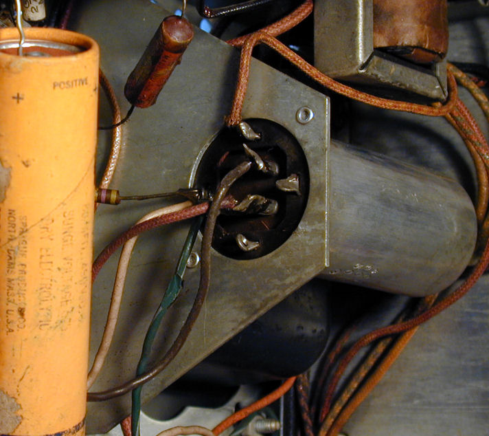
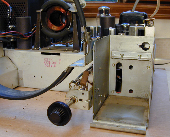
Setting the chassis on its side, you will see the other connections.
A board with five terminals protrudes through a slot in the back
of the tuner cage. Unsolder all six leads (four wires and two resistors).

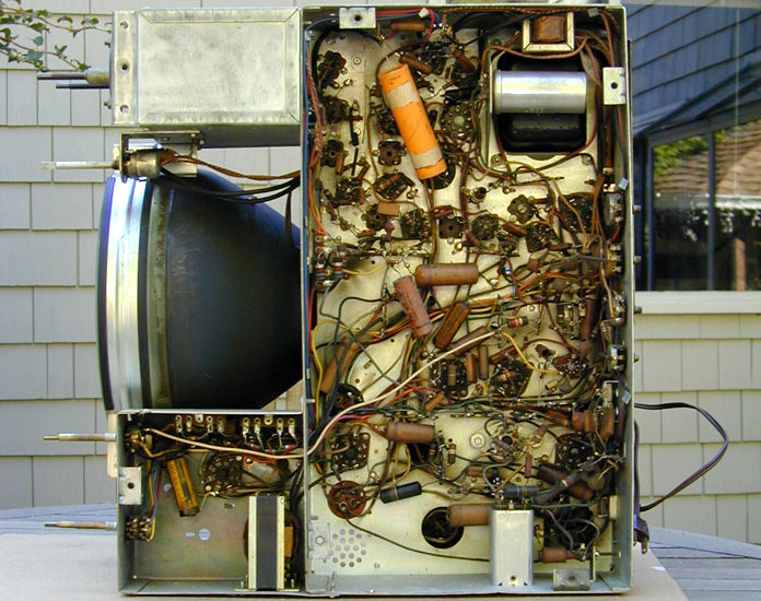
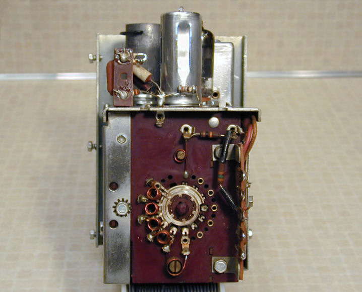
Several screws secure the tuner cage to the chassis. You must remove the picture
tube to reach all of them. Here, the CRT and tuner have
been removed and you can see the tuner's terminal slot in the chassis.

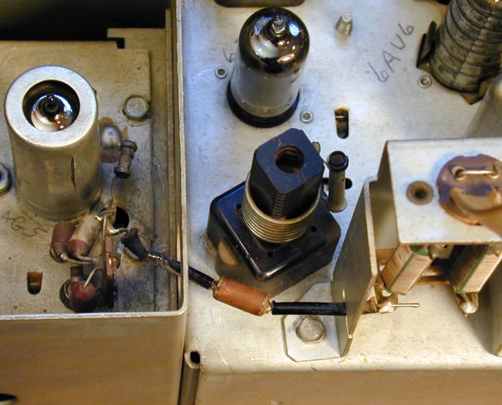
With the CRT removed, I could see the chassis number KCS38
stamped in red ink. The little paper capacitor tucked in by
the volume control can also be replaced at this time. It's
an easy one to overlook.
Here is our victim in all his grimy glory, coated with decades of
tobacco tar and household cooking grease. Notice the three screws
in the edge nearest the camera. Always put screws back in the holes
they came out of. Then you won't mix up screws of different sizes,
or discover that you're missing some when it's time to reinstall the tuner.
Visible at the rear is the little terminal where I unsoldered the lead
from the antenna transformer.

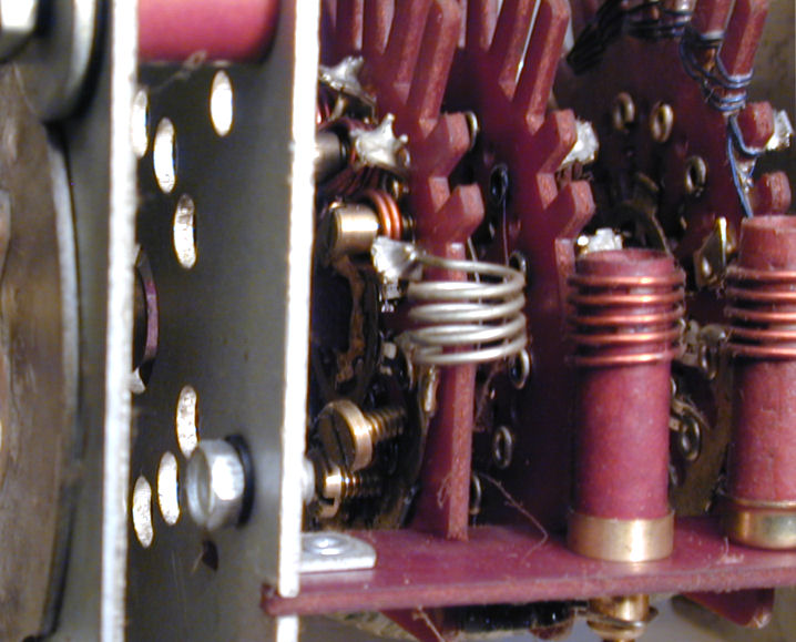
Next, I have removed the tuner's shield and turned it upside down.
The innards consist of several switch wafers and assorted coils
and resistors. At left, you can see the five-terminal board
whose leads I unsoldered a few minutes ago.
Before we start cleaning, here's a little surprise.
Yes, that's a loose screw hanging slantwise out of
its hole. I found another just like it rolling around the tuner
cage. These are the oscillator adjustment screws for channels 7 and
12.

Perhaps someone was twisting screws in a vain
attempt to make those channels come in. Don't loosen a
screw all the way if you're adjusting the RF oscillator
(rarely needed, by the way). It was a major pain to get
the loose one back into its hole.
Tuner Cleaning Dos and Don'ts
If you're asking whether now's the time to hose everything down with
electronic spray, the answer is a stern No!
RCA factory literature warns against sprays of any kind,
which may damage composite materials, or, in a later type of tuner,
change the value of a neutralizing capacitor.
I have gotten excellent results by hand-cleaning all of the
wafer contacts with DeOxit and Q-tip swabs. You can buy DeOxit as
a liquid, but most people get the spray cans. Spritz a little
into a small container and dab your Q-tip into it, then
rub the switch contacts as you rotate the tuner. It demands
patience and a strong light to reach everything. Take your
time. This is a job you only want to do once.
I also cleaned grime from the rest of the tuner interior, using 90%
isopropyl alcohol and more Q-tips. This may not be necessary,
but I don't like to leave dirt behind in a job like this.
After the contacts were clean, I went over them again using
Q-tips and a suitable electronic lubricant. Don't skip this step
or your tuner will feel stiff and wear out prematurely.
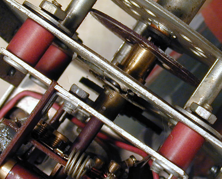
The detent mechanism in the tuner front also needs cleaning
and relubrication. At center in
the next photo is a ball bearing peeking
out from between a little pressure plate and a metal race. Above
the ball is a dab of whitish grease.

The ball is part of the tuner's detent mechanism, which
clicks into position as you turn the selector knob to each channel.
The ball moves around a circular race. When it comes to a new channel,
the pressure plate presses the ball partway into a hole, where it
rests, holding all of the tuner's switch contacts in alignment,
until you turn the knob again.
After 59 years, most of the old grease in this mechanism was
long gone. What little remained around the edges was as hard
as old taffy. I carefully cleaned away the dried grease with a wooden
toothpick and popsicle stick. Then I sparingly applied white
Lubriplate grease to the ball and all around the race, using
tiny dabs on the end of a toothpick.
I also used Lubriplate on the fine tuning mechanism.
On this TV, the fine tuner moves a slug up and down inside the tuner
body. A rotating fiber cam drives a little lever up and down, just
like an oil derrick. Lightly grease the cam where the lever
slides on it to ensure smooth operation.
Our cleaning marathon is finished! Here's a shot of the backmost
switch wafer. Previously, it was dark with oxidation
and dirt.

The tuner's interior is chock full of little coils
like those seen in the previous photo. Don't
bend or damage these delicate coils, or you'll live to regret it.
Don't replace any resistors, either, unless you have the equipment
and expertise to realign the receiver.
After reinstalling the shield, I cleaned the exterior,
just for fun. This doesn't improve performance,
but it makes me feel better, after doing all that
work that nobody will ever see.
Hello, Fawlty Towers . . .
With everything back in place, I was startled at the improvement.
The TV still had horizontal issues, and I hadn't checked out the
AGC, but the picture and sound were greatly improved.
For this trial, I hooked up a DVD player that can send output to
either channel 3 or 4. Both looked equally good, as did reception
from my home transmitter, which was currently broadcasting on
channel 5. I tested other channels using my Sencore VA62A universal
video analyzer, a bulky solid-state device that creates test
signals for any channel.
Everything looked good, including channels 7 and 12, whose
oscillator screws I had adjusted about midway after reinserting
them in the tuner.
Tuner cleaning was tedious, but it was well worth the effort.
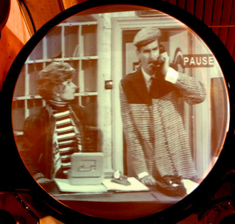
Controlling the Horizontal
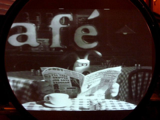
The horizontal synchronization was still lousy.
Lock was easily lost when changing channels, and it disappeared completely
after about ten minutes, suggesting that a component was changing value
after it heated up. The next photo shows the screen just before sync evaporates.
We see leftward "tearing," and pull-in at the right side. The
image is actually cut in half and wrapped around the screen. In the
real image, Basil Fawlty sits at Sibyl's left and she stands at the
right screen edge. Here, she is moved to the center. To her right
is the vertical blanking bar—normally off the screen during the
horizontal retrace interval—and Basil's part of the image
is wrapped around at the right.
The horizontal oscillator is still running too fast, although not as fast
as previously, when the screen contained almost two complete images.
I followed the factory drill for adjusting the horizontal oscillator,
but the problem persisted after warmup. Looking closely at the
schematic, I noticed a coupling capacitor leading to the oscillator
tube. Its value (.0022 mfd) suggested it was a paper cap, but I
hadn't checked it off as being replaced.
This was one case where keeping notes of my work really helped.
Sure enough, the original tiny cap was hiding under a terminal board,
concealed by a mica capacitor and resistor. Here is the replacement
after I carefully nudged the other components aside.
Bingo! After readjusting the oscillator frequency, the horizontal lock
was stable, even after warmup. But now I saw something new. In
the next photos, notice the faint purplish or brighter blue tinge
at the upper left and lower right edges.

Color in a Black and White Tube?
The color difference looked strange to me. Aren't black and white tubes
supposed to look black and white? I readjusted the ion trap on the picture
tube, to make sure it wasn't creating any edge shadows. That
didn't cure the problem. The color difference was still there, most
obvious in bright scenes with low contrast, and visible to anyone
regardless of room lighting.
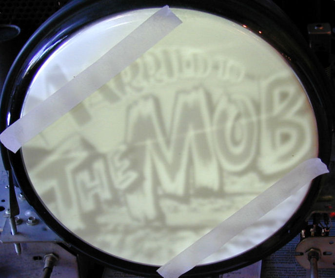
Another TV guy suggested rotating the picture tube, to isolate whether
the problem was in the tube itself. Before
doing so, I marked the tube with strips of tape to roughly match
the problem areas. I also cranked up contrast and brightness to
accentuate the color change.

This led me to a solution. Can you guess what it was?
I noticed that, if I rotated the tube clockwise, the colored
areas would roughly match the area not seen when the TV is installed
in the cabinet and the tube is behind its rectangular mask. I turned
the tube and adjusted the vertical height to fit the mask.
Problem solved. My theory is that this is a high-mileage tube,
operated, as most round tubes were, behind a rectangular mask in
the cabinet. The
area scanned by electrons grew more brownish with age, producing
a color contrast. Or, perhaps the scanned center area was simply dimmer and
the color difference was a trick of the eyes.
Regardless of the cause, moving the problem zones out of the viewed
area did the trick.
Can We Go Home Now, Mom?
The previous picture looked decent, but not perfect. Brightness and
contrast weren't the greatest, and I still didn't like the horizontal
linearity and width.
Time for another round of adjustments! (We'll be home soon, kids.)
A dim picture can arise from several causes, including a weak picture tube.
Speaking of which, I was still using the spare CRT, which had never
actually been checked. I put it on my Sencore CR70 tester and confirmed that it
was in fine shape, with high emission and a good score on the
"life test." Whether aged or not, it looked strong enough
to run a marathon.
The AGC had put questions in my mind throughout this restoration, so I
carefully set it as described in the manual. I also adjusted
the ion trap, the horizontal oscillator, horizontal locking range,
horizontal linearity, and vertical height and linearity.
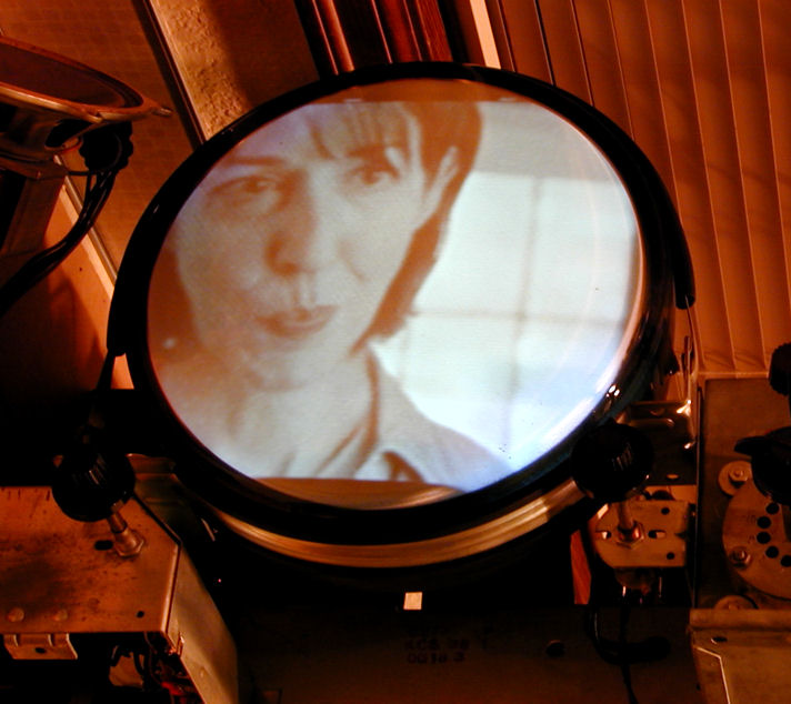
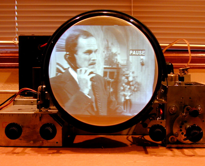
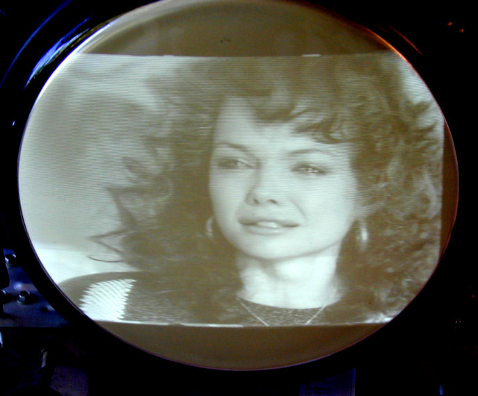
Here's the result. The first pic is
a still image snipped from digital video that I took. The second was shot
live, without pausing the VHS tape playing on the TV.

This picture's as good as any restored television in the house, including
my beloved RCA 630TS. Before wrapping
things up, I wanted to confirm that the horizontal was as good as I could make it.
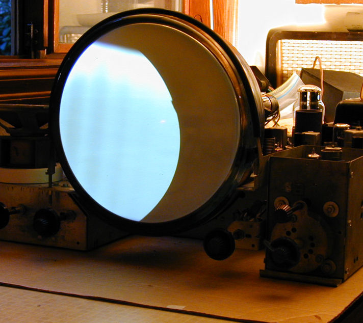
What Does the Oscilloscope Say?
I decided to check the horizontal waveform using an oscilloscope. This
would be a good time to practice my mediocore 'scope skills and to compare
this crucial waveform to the theoretical ideal.
Here are the instructions.

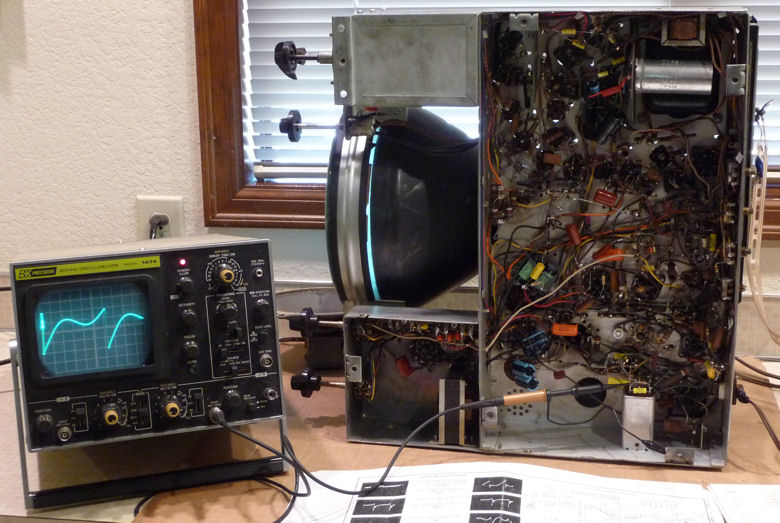
The first photo gives a "before" view of the waveform. Its shape is generally
correct but the peaks aren't level. The scope's probe is connected to
terminal C of the horizontal oscillator transformer, as directed.

Notice the ladder-style antenna cable connected to the chassis rear. The
TV is using rabbit ears to receive an over-the-air signal from my home
transmitter. This approximates the real environment the television was
designed for.
The second photo shows a better waveform. (Oh, duh. Had I read the instructions
more carefully before starting, I would have noted that I needed to flip the
chassis the other way to access both adjusters, one
through a hole in the side of the chassis.)

Now the waveform peaks are level.
The little mirror lets me watch the picture during adjustments.
The instructions require frequent switching off signal and back on again,
followed by adjustment of the hold control.
All of the horizontal adjustments are interactive to some extent, so
after the waveform looked right, I did another round with the horizontal
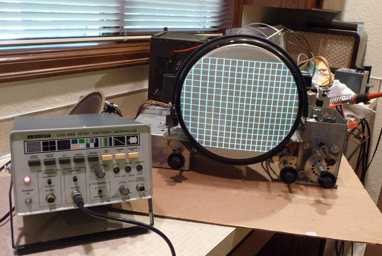
locking range, drive, and linearity. Switching to a pattern generator,
here's what I saw.

The picture is rock solid with great action on the horizontal hold. I
couldn't get the linearity perfect, however. The squares on the left side
are wider than those on the right, and the center dot isn't centered
in the CRT. With different combinations of adjustments, I could make
the pattern look worse (or degrade horizontal stability), but I couldn't make it better.
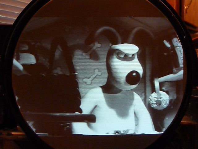
I Hereby Declare Victory
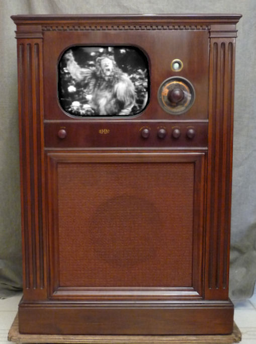
That degree of non-linearity can be seen in a test pattern but isn't
really noticeable in normal viewing. (Look back at the photos of
Wallace and Gromit if you don't believe me.) I had already replaced just about
every related component, apart from the linearity coil itself, so I decided
to quit while I was ahead.
This TV's picture is bright, crisp, and stable, and its audio is
excellent. Not bad for a sixty-year old! All I have left in this
project is to replace the torn grille cloth and polish the knobs. Meanwhile,
I'll put the TV back in its cabinet and enjoy some old movies.
It Ain't Over 'Till . . .
Soon after that, I brought the TV into our family
room to watch a movie with my wife and son. Although the picture was fine,
the sound was faint. The TV was watchable in a large room, but only
with the volume turned up all the way, something I hadn't noticed when
playing it on the workbench with my ears two feet from the speaker.
The horizontal off-centering bugged me, too, so I hauled it back
to the workbench again.
It took only a few minutes to adjust
the audio IF (intermediate frequency) transformer and
discriminator to produce more volume with no loss of fidelity.
Although this television doesn't have electronic centering controls,
I was able to center the picture by adjusting the tension
screws on the focus coil.
I'm going to call this the "Family Room Test." A television project
isn't truly finished until you can watch a full-length movie with
the TV in its cabinet, where things run hotter. You are not allowed
to make any comments about the TV's performance, either praise or
apologies, and if you leap up midway through the movie to fiddle
with anything, the TV flunks the test!
In fact, some service shops did much the same thing, playing
the TV in its cabinet for several hours before returning it
to the customer as fixed.
Here's the T-100 in its current condition. The picture is nice and bright, as
you can see. Perhaps some day I'll find a close match for the grille cloth.
In the meantime, this TV looks and sounds great.

Do You Have Enough TVs Yet?
A couple of days before finishing this project, I stumbled across another television
on the local craigslist. It was another postwar classic, a 1948 DuMont RA-103
in a Meadowbrook console cabinet. And another low, low price of $40. Such bargains!
The photo shows the restored TV, several months after I got it.
You can read the whole story in my DuMont RA-103 article.
|