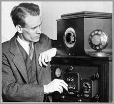
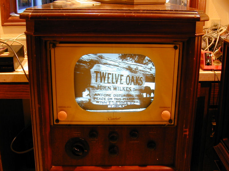
Capehart-Farnsworth 661-P Television (1948)


Charming, distinctive, and seldom seen, this 1948 Capehart-Farnsworth 661-P
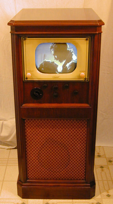
television is a favorite of mine. With a 10-inch picture tube and a tall,
slim profile, it takes up less space than most vintage consoles, a
bonus in our crowded home.
Finding the Capehart-Farnsworth 661-P
When I saw this Capehart-Farnsworth advertised 150 miles away, I made a beeline to the owner's
house for a look. The asking price was $250, but after I pointed out some
issues, including a damaged picture tube, they parted with it for a
reasonable $120.
Although I had intended to remove the chassis for transport, everything seemed
very secure when I checked it out. I removed the knobs, and then, with the seller's
help, carefully laid it on quilts in the back of my SUV.
First Look
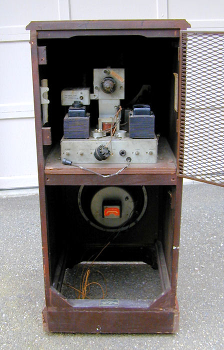
Here is the TV, immediately after I unloaded it at home.
The cabinet stands 42 inches high, 19 wide, and 22 deep. It's in decent
cosmetic condition, with minor scuffs, many tiny dots of latex paint,
and a couple of little scrapes in the grille cloth.
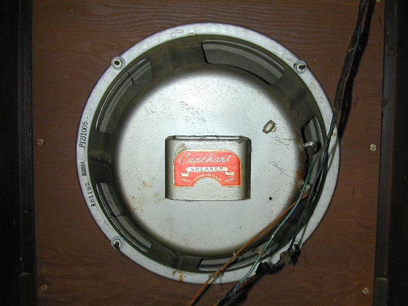
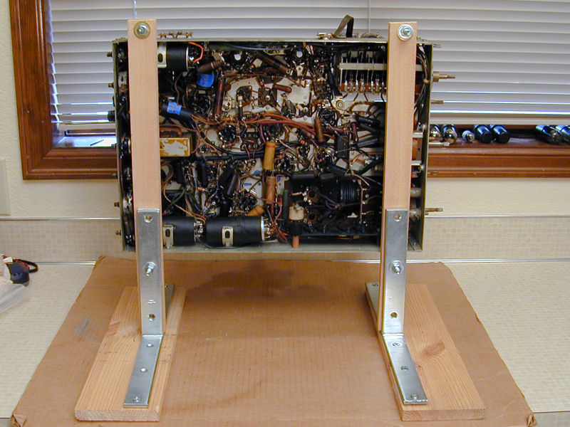
From the rear you can see the chassis above and a generous
12-inch speaker below.
The hinged metal cover has been swung open in this view. The power cord
mounts on that cover with a safety interlock.
Here's a closer view of the speaker. Capehart's high-end radios were known for
fine audio, so I'm curious to hear what this TV sounds like.

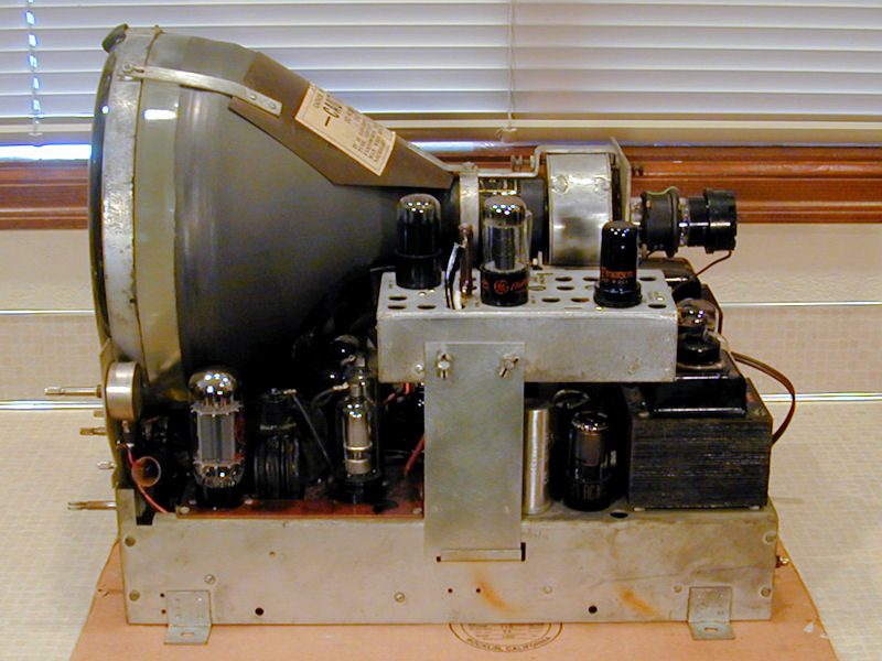
A peek at the chassis reveals why I wasn't willing to pay top dollar
for this TV. The tubes are all missing, except the picture tube, whose
base has been torn off. The CRT socket is lying in one of the
empty rectifier tube sockets.
The small tubes are common types, so they won't be difficult to find, but replacing
a couple of dozen will cost a bit. The picture tube is a bigger problem. Although it's
possible to reattach a base if the wires are intact, that tube might be a dud for
all I know, which could add another $100 to the parts bill . . . if I could find
another good one.
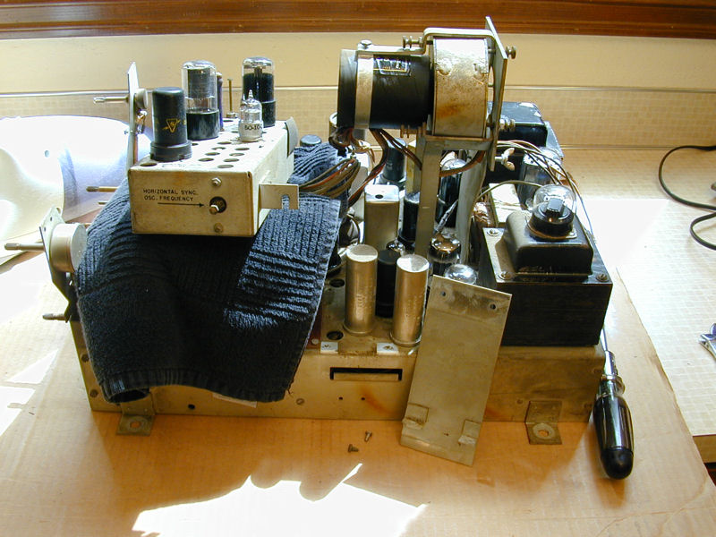
Two notable features are seen in the previous photo. There are two
power transformers and the one on the left has a rotary switch, likely to
adjust for different line voltages. Mounted up and behind the left transformer
is a small subchassis that houses horizontal sync circuitry.
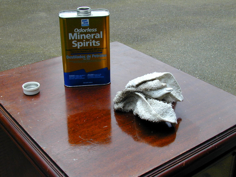
Before bringing the TV indoors, I wiped the cabinet inside and out with
mineral spirits. I'll clean it more later, but at least this will
remove any mildew and spiderwebs.

Who Were Capehart and Farnsworth?
The Capehart-Farnsworth moniker links two notable figures in radio-television
history, although they were not partners, and each of them eventually
lost the company that bore his name.
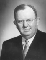
Homer Capehart
Homer E. Capehart was a businessman and politician who grew wealthy manufacturing
phonographs, radios, and jukeboxes, and served as a Republican Senator from
Indiana from 1944-1962.
Starting out as a salesman, Homer Capehart founded the Automatic Phonograph
Corporation in 1927, which became the Capehart Corporation in 1928, with
headquarters in Fort Wayne, Indiana.
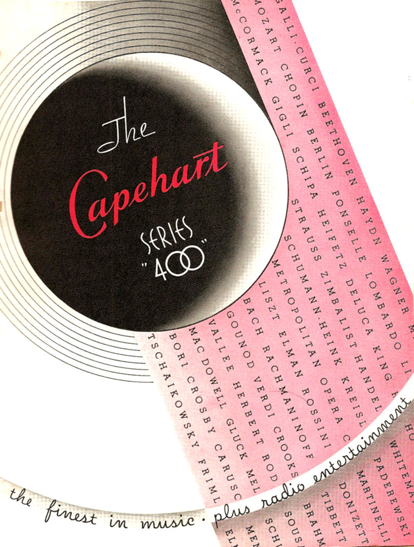
Capehart phonographs and radios from the late 1920s and early 1930s were aimed at
the luxury market, housed in large, ornate cabinets and sporting lofty names like
Amperion and Orchestrope. Nowadays, certain Capehart sets are eagerly sought by
collectors, particularly for their audio components.
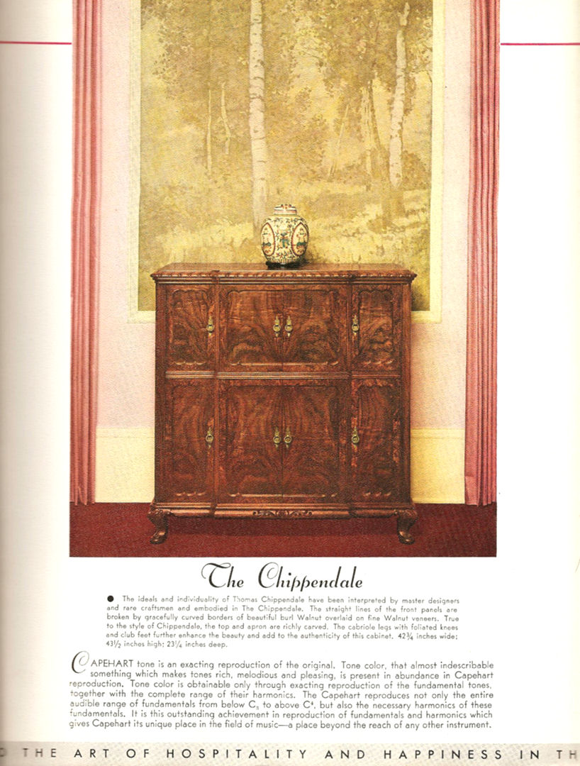
Here is a brochure for the 1932 Capehart 400 radio/phonograph
in a Chippendale cabinet:
From early days, Homer understood the market
potential of an improved record changer. Devised in 1928, the Capehart
Turnover record changer
could play both sides of a record and it could also play records of different sizes.
By 1932, Homer had been pushed out of his own company by investors. He
promptly bought the rights to the Simplex Multi-Selector automatic record changer,
which allowed patrons to choose a specific record rather than play whichever record
came next in the stack.
In 1933, the Simplex changer was bought by Wurlitzer, which was then on the
brink of bankruptcy. Homer Capehart also joined Wurlitzer, where, as
vice president and sales manager, he achieved a dramatic turnaround
in the company's fortunes. Before Capehart, Wurlitzer leased fewer than 300 jukeboxes,
or roughly 1% of the US market. Three years later, under Capehart's aggressive
leadership, the total jukebox market had tripled and Wurlitzer's
share had skyrocketed from 1% to nearly 50%.
This
video
shows a 1936 Wurlitzer Model 412 with Simplex changer, playing a song.
While early Capehart products had been marketed to the elite, the
jukebox, used in public places, was pitched as a democratizing
influence. Speaking as a Wurlitzer executive, Homer Capehart declared that,
"Poor people have the right to enjoy good music with their beer
or sandwiches."
In 1938, six years after Homer's departure, the Capehart company
was bought by Farnsworth for its brand recognition and
manufacturing facilities.
By the 1940s, Homer had turned to politics. He was elected as a Republican
Senator and served three terms, under Eisenhower and Kennedy, until his defeat in 1962.
Capehart-named products, under different owners, were sold until 1965.
Homer passed away in 1979.
Philo Farnsworth
Philo T. Farnsworth was a Utah farm boy who became interested in
electronic television in his teens. Prior TVs were largely mechanical,
relying on devices such as mirrors or spinning discs. In 1930,
Farnsworth received a television
patent
based on his "image dissector."
Although Farnsworth fans sometimes call him the inventor of television,
that's an exaggeration. Television, like the automobile, was not
invented by a single person. Both were complex devices whose time had
come, and both were the result of people developing similar ideas in
parallel—and often in competition—over a period of decades.
Farnsworth was embroiled in patent litigation with RCA during the
1930s and he sought connections with the British company of John Logie Baird,
a Scot who had created a successful mechanical TV system.
He worked at Philco for a couple of years and his image dissector camera
tube was one of two types adapted in Germany to televise the
1936 Olympics
in Berlin. (The other type was the iconoscope, which later formed the
basis of United States television broadcasting.)
By 1938, the Capehart company was fizzling and Farnsworth had left Philco.
Having gained a $1 million licensing payoff from RCA for his 1927 patent,
Farnsworth bought the Capehart company. He moved to Fort Wayne, home
of the Capehart factory.
The new company was called the Farnsworth Television & Radio Corporation and
it sold electronics, including my 661-P television, under the Capehart and
Farnsworth names. Capehart supplied a factory and a bankable reputation, while
Farnsworth supplied engineering drive and a desire to develop consumer products.
Both names were used in postwar advertising, with Farnsworth representing economy
sets and Capehart the luxury line.
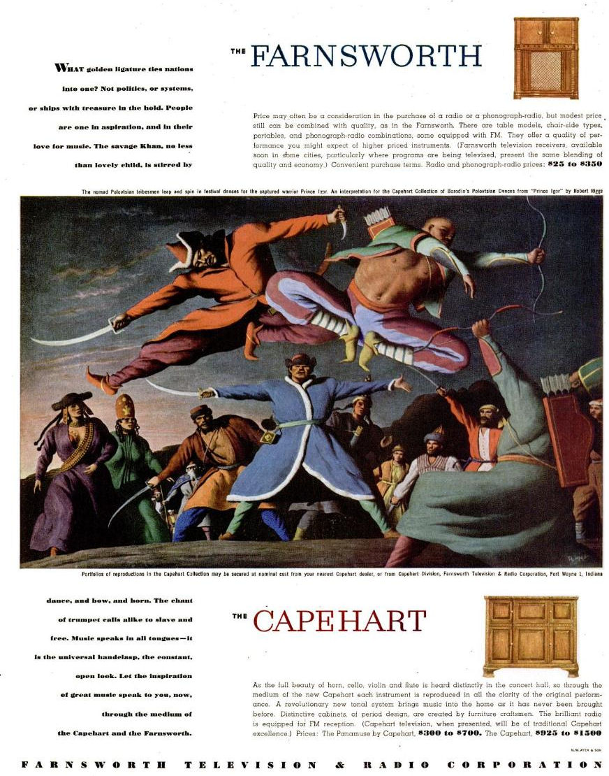
In this Life magazine ad from September, 1946, Farnsworth radios present a
"blending of quality and economy" and they are priced from $25-$350.
Capehart "instruments" are aimed at the well-heeled music lover and
they are priced from $300 to a regal $1500—the cost of a new automobile.

The 1946 product line didn't include TV. The ad promised that television
receivers would be "available soon in some cities, particularly where
programs are being televised."
By 1947, television made its first appearance in a Farnsworth ad. Notice the
little tabletop in the lower right corner:
Evidently, Farnsworth TVs weren't quite ready for market. No
model number is given for that set, and while it resembles a model GV-260, the
ad states, "AM radio also available." In fact, no Farnsworth
tabletop of the 1940s included a radio, and given the already crowded cabinet,
it would have taken a miracle to shoehorn a radio chassis in there, too.
The GV-260
did reach the market in 1947 and its streamlined cabinet makes it highly desirable
to collectors. The Early Television Foundation owns a rare GV-260 prototype
and their article
provides interesting details about that model.
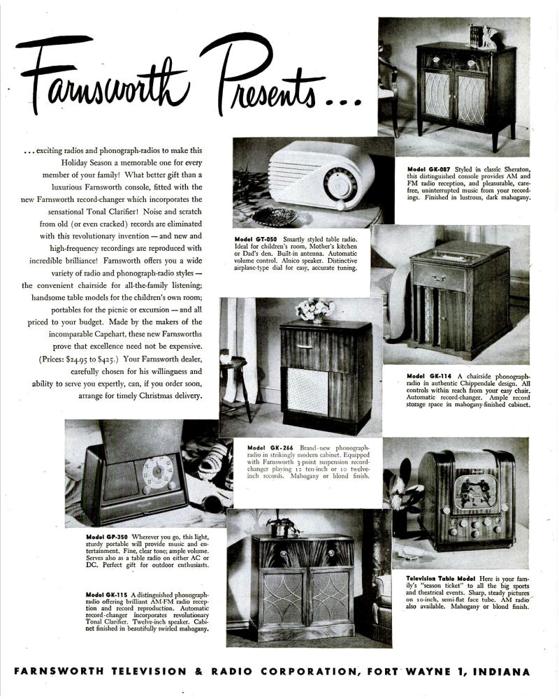
1948 brought new Farnsworth TVs, including my model 661-P. The
610-P
and 651-P
look exactly like the 661-P, except in a smaller tabletop cabinet. The mammoth
501-P was a
TV/radio/phono in a breakfront cabinet, seen here in a 1948 ad:
(The 501-P looks imposing, but if I'd designed the cabinet, I would have
put the TV screen in the middle, at a comfortable viewing distance,
rather than on top, where seated viewers had to crane their necks to watch it.)
Farnsworth's company prospered from government contracts during World War II,
but it wilted in the postwar years. In 1949, he was forced to
sell the company to International Telephone & Telegraph. Philo spent his
remaining years primarily doing research into other subjects.
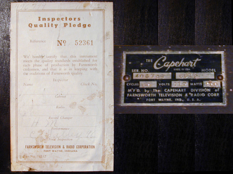
Since the company resulted from acquisitions, you will find the names Farnsworth, Capehart,
and Capehart-Farnsworth used somewhat interchangeably. My TV's serial number plate
and service manual calls it "The Capehart," built by the Capehart division of the
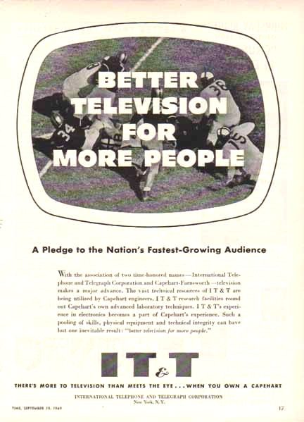
Farnsworth TV & Radio corporation. This 1949 IT & T ad describes the merger of
IT & T and "Capehart-Farnsworth television," referring to "Capehart's advanced laboratory techniques" and reducing Philo to a mere hyphenate:

Farnsworth radios are much easier to find than televisions.
My GT-051 and ET-064 Farnsworths were built in Fort Wayne in the late 1940s.


The company sold TVs in small numbers throughout the 1950s and it ceased production in 1965.
These televisions were conventional for their time, reflecting technology commercialized
by other companies, notably RCA. By the mid-1950s, the Farnsworth name had all but
disappeared. IT & T marketed its TVs as Capeharts and fine print at the ends of
ads identified the company as the Capehart-Farnsworth division of IT & T.
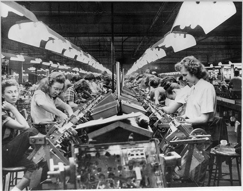
The Library of Congress has an interesting photo of women working the TV assembly
line at Fort Wayne in the early 1950s. Then, as now, electronics were designed primarily
by men and assembled primarily by women.

Although their names appeared on the labels, I doubt that
Homer Capehart or Philo Farnsworth had any real involvement in
the 1950s products. By then, Capehart was serving in the U.S. Senate and Farnsworth
spent his time researching subjects like radar and nuclear fusion.
Philo spent his later years pretty quietly, one exception being a 1958 appearance
on the TV show I've Got A Secret, where he successfully stumped the panel
and declared that he "invented television at age 14." He passed away
in 1971.
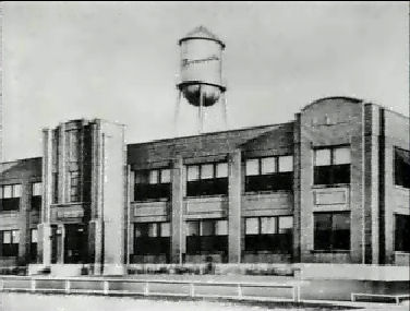
The old Farnsworth factory in Fort Wayne was demolished in 2010:

So, what was Farnsworth's true legacy? That will be debated for as long
as people watch televisions. To some people, he personified the myth of the lonely
inventor, sparked by inspiration and struggling against mighty forces to
bring his ideas to life. Others see him as a stubborn hick, weak in
business sense and delaying the adoption of television for years through
his refusal to play nice with others. My personal view falls somewhere
between those extremes.
You can learn much more about early television history at the
Early Television Foundation website.
Description
The Farnsworth 661-P uses a ten-inch 10FP4 picture tube, equivalent to the 10BP4, which
was the most popular late-1940s CRT. The 10BP4 was used in my 1946
RCA 630TS as well as my
RCA 721TCS,
Admiral 24C15,
Hallicrafters T-67,
RCA T-100,
Westinghouse H-181,
and many other sets by various companies.
A memorable feature of this TV is its tall, narrow console cabinet.
Most 10-inch TVs were either tabletops, such as
my Hallicrafters T-67 and RCA 630TS, or larger
"combos" that housed a TV, radio, and phonograph in one
cabinet. Admiral made a few 10-inch TV-only consoles, such as
my 24C15, and RCA made the notable
721TCS.
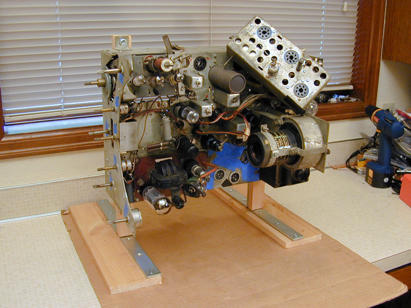
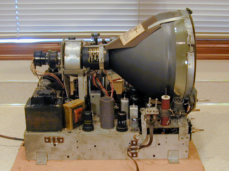
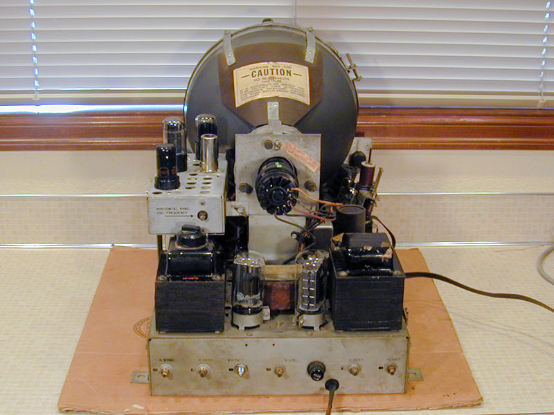
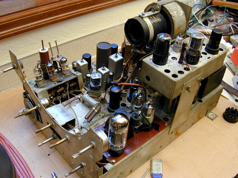
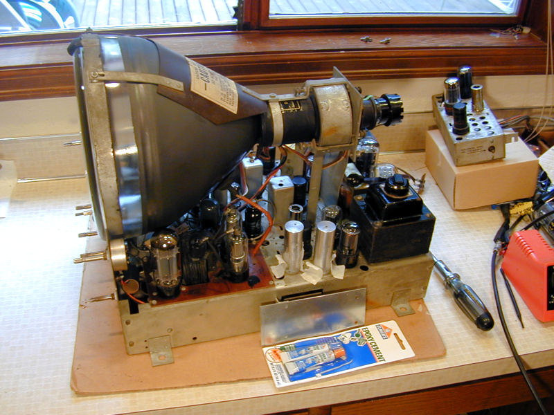
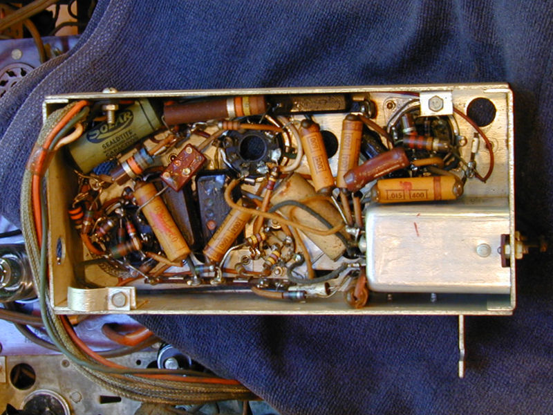
Here's a look at the restored chassis.


In the first photo, you can see the tuner at lower right, mounted at a slight
angle from the main chassis. The third photo shows how the horizontal AFC
(automatic frequency control) subchassis is suspended above the main chassis.
A two-page schematic is available from Sams, folder
95A-1.
The factory service manual is much more detailed; click the following icon to download
the 15-megabyte file. (Thanks to
Chuck A for scanning and hosting this manual.)
Much of the 661-P's electronic design is similar to other TVs of the day.
The horizontal AFC circuit is the
RCA "Synchrolock" system, a carbon copy of which is used in my
630TS.
The 661-P and 630TS both use a "split sound"
audio system, and, consequently, both TVs use more tubes than later sets:
29 in the 661-P and 30 in the 630TS.
The power supply has two transformers and two low-voltage rectifier tubes.
Each transformer supplies roughly half of the tubes in the TV.
One transformer, labeled "Television" in the manual, is
switchable for different line voltages.
The high-voltage section uses a voltage doubler with two 8016
HV rectifier tubes; the 8016 is equivalent to the more common 1B3GT.
Here are the types and functions of the Capehart's tubes.
| Tube |
Type |
Function |
| V1 |
6J6 |
RF amplifier |
| V2 |
6J6 |
Mixer |
| V3 |
6J6 |
Oscillator |
| V4 |
6AC7 |
1st video IF amplifier |
| V5 |
6AC7 |
2nd video IF amplifier |
| V6 |
6AC7 |
3rd video IF amplifier |
| V7 |
6AL5 |
Video Det./DC rest./Sync sep. |
| V8 |
6AU6 |
1st video amplifier |
| V9 |
6K6 |
2nd video amplifier |
| V10 |
6BA6 |
1st audio IF amplifier |
| V11 |
6BA6 |
2nd audio IF amplifier |
| V12 |
6AU6 |
3rd audio IF amplifier |
| V13 |
6AL5 |
Discriminator |
| V14 |
6J7 |
Audio amplifier |
| V15 |
6V6 |
Audio amplifier |
| V16 |
6SK7 |
Sync amplifier |
| V17 |
6SH7 |
Sync stripper |
| V18 |
6SN7 |
Sync clipper/Sync clipper |
| V19 |
6SN7 |
Vertical Oscillator |
| V20 |
6SN7 |
Vertical amplifier |
| V21 |
6AC7 |
Reactance |
| V22 |
6K6 |
AFC oscillator |
| V23 |
6AL5 |
Sync discriminator |
| V24 |
6L6 |
Horizontal oscillator |
| V25 |
5U4G |
Low voltage rectifier |
| V26 |
5U4G |
Low voltage rectifier |
| V27 |
8016 |
High voltage rectifier |
| V28 |
8016 |
High voltage rectifier |
| V29 |
10BP4 |
Kinescope |
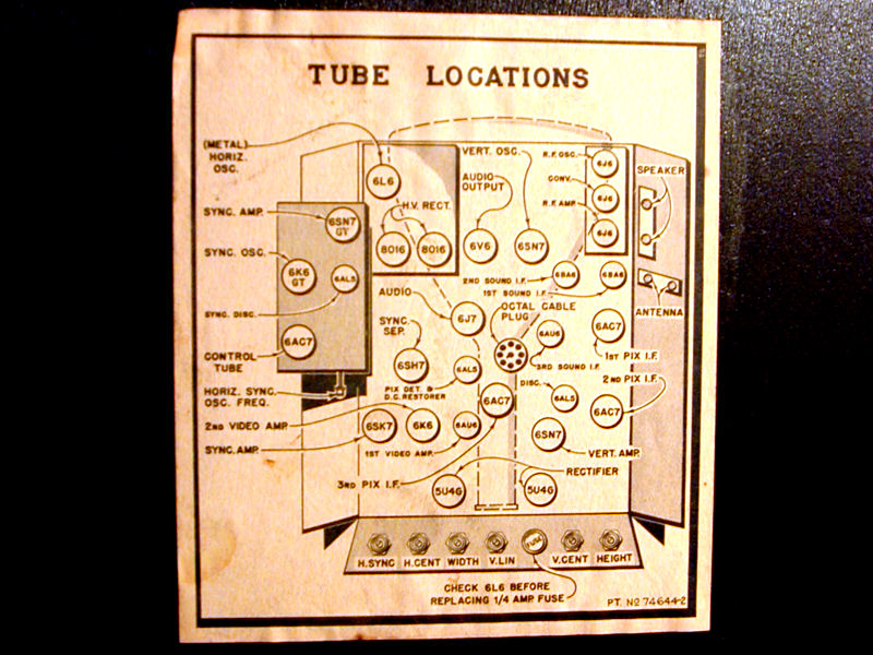
The 661-P's deep, narrow chassis made for a compact cabinet, but it didn't simplify
life for the serviceman. As the tube layout diagram shows, several of the 661-P's tubes
are well hidden under the picture tube. Some are impossible to remove
without pulling the chassis from the cabinet.

The inspection label and serial number plate are located on different parts of the cabinet,
but I combined them in one photo, which identifies this as set 496799:

I would not take that number to suggest that Farnsworth—a small company—made
nearly half a million of these TVs. Manufacturers used many different schemes for
serial numbers, which don't necessarily refer to a single model or even start
numbering at zero, for that matter.
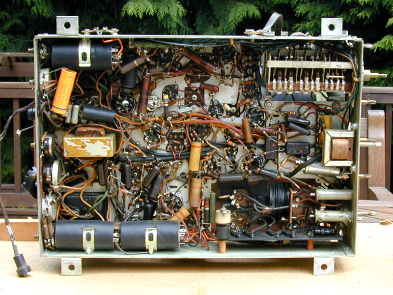
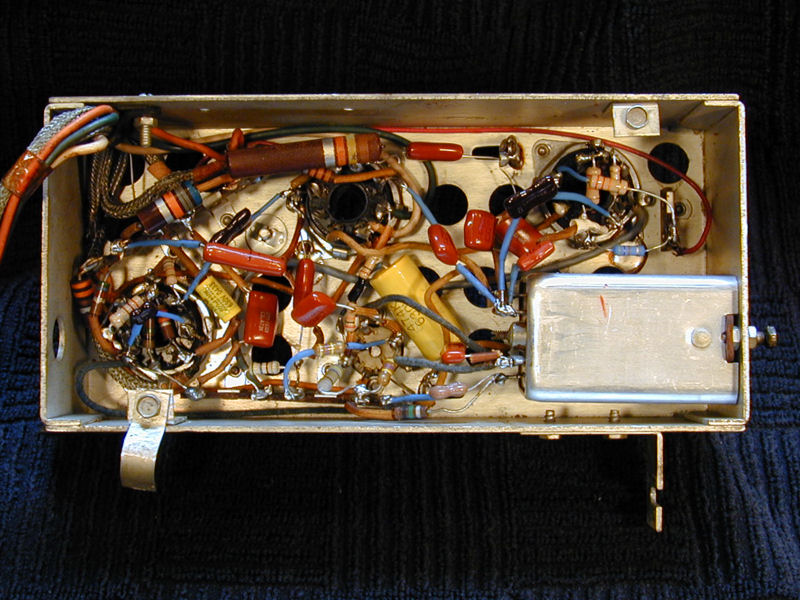
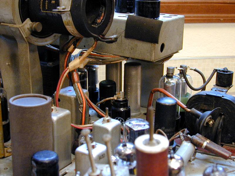
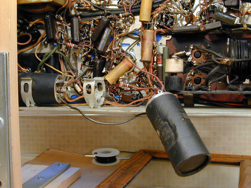
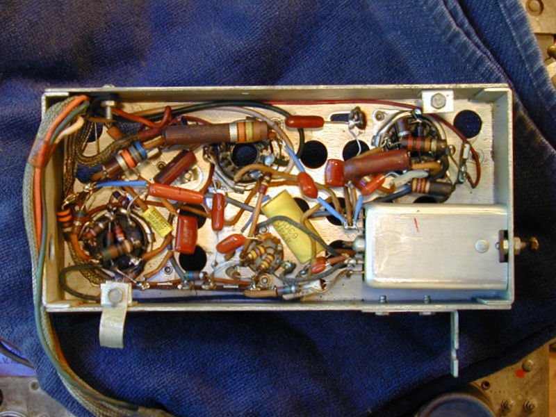
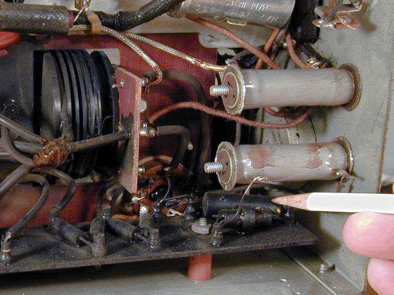
Here is our first look beneath the unrestored chassis:
The three big black cylinders contain nine electrolytic capacitors for
the power supply. At lower right is the high-voltage section and at
upper right is the tuner.
The tuner is unusual. Unlike the conventional turret or wafer types, it uses
ganged air variable capacitors, more often found in
communications radios.
These capacitors tune continuously by their nature, but the tuner has
mechanical detents to make it click into place for each station. A
similar General Instruments tuner is found in my
Scott 800/B radio/TV/phono console.
Here's a view of the tuner from the side, above the chassis. Although many tuners
are fully shielded to reduce interference from external sources,
this one is somewhat open to the breezes.

Electronic Restoration
I always work on the electronics before the cabinet and
other cosmetics. If a TV can't be made to work, I don't want
to invest a lot of money or time making it into a
beautiful but useless "shelf queen."
Cleanup
The chassis was covered thickly with dust, but that
was easily cleaned up and I saw no rust underneath.


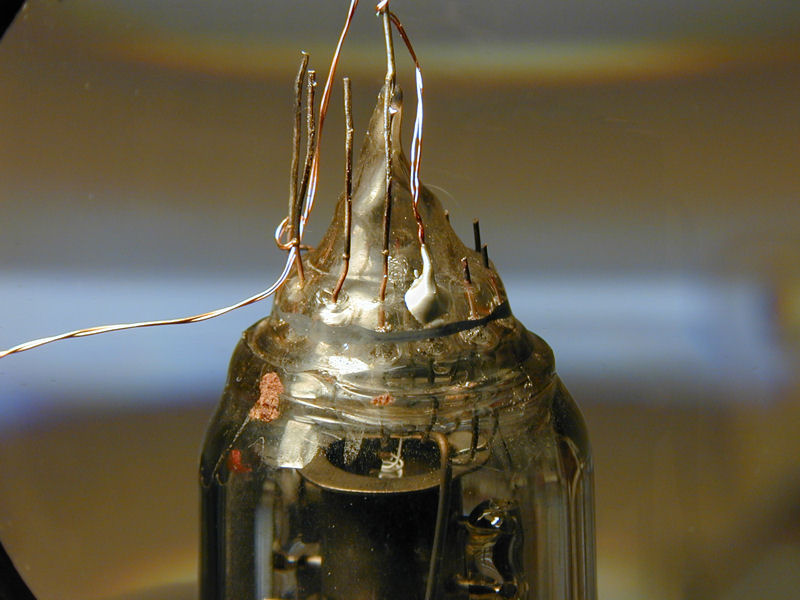
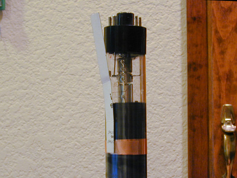
Moving indoors, I took a close look at the picture tube base. Not
encouraging! The 10BP4 CRT base uses five leads. Four of them are intact,
although bent, but the fifth is broken off flush with the glass.
Who knows whether this can be repaired?

In the previous photo, you can see this TV's unusual ion trap
magnet, which is shaped as a wide, full collar rather than a curved
magnet held by a narrow clamp. Removing the magnet tells us that the
tube is a 10BP4, and now we can see that the broken lead (left
arrow) connects to the CRT's second grid (right arrow). The
10BP4 data sheet
tells us this is the lead for pin 10.

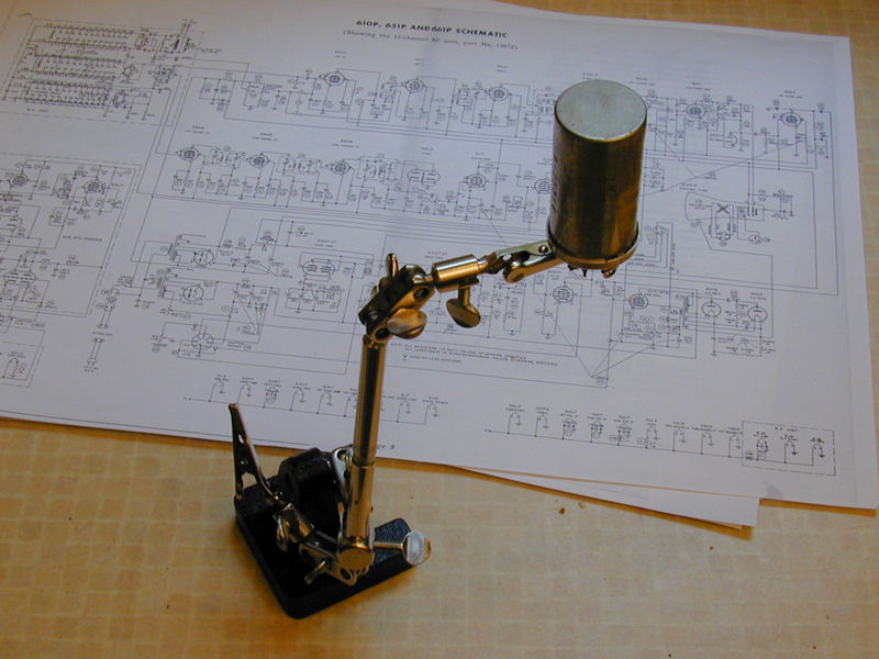
Repairing the Picture Tube Base
This looked grim, but I had read about
reattaching loose CRT bases, and even repairing a broken lead by grinding
away the glass and soldering a new wire to the stub.
Calling on the VideoKarma
TV forum for advice, I got several
suggestions, including tips on how to grind the glass with
a tiny diamond burr or how to secure a new lead with
silver-filled epoxy. For more details, I'll refer you to
that discussion.
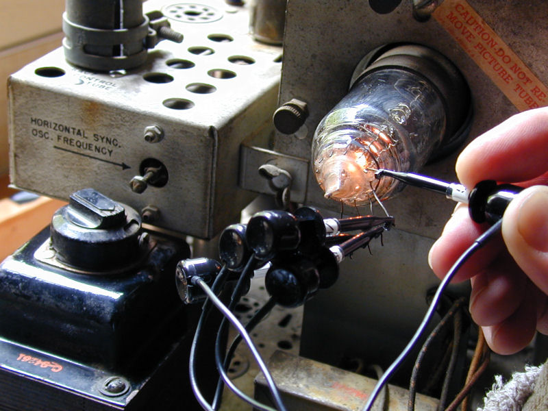
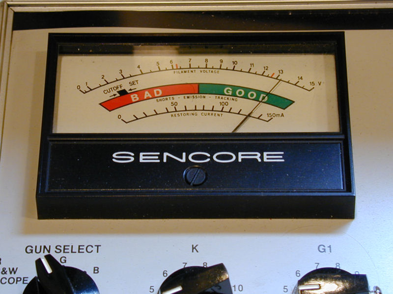
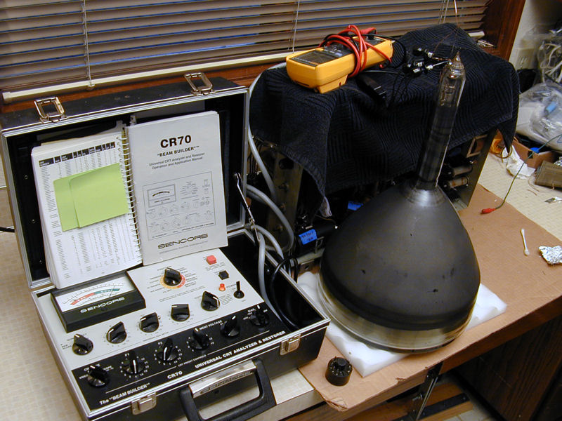
Before attempting the repair, I tested the CRT using the universal adapter
on my Sencore CR70 tester. If the tube's a dud, why waste time trying
to fix the base? The stub was too short to grip with a test lead, so I held the lead
against it.


Woo-hoo! This CRT's emission is as strong as any I've seen on that tester. It would be
a shame to discard it without chancing a repair, especially since the last
CRT rebuilder in the United States closed up shop last year.
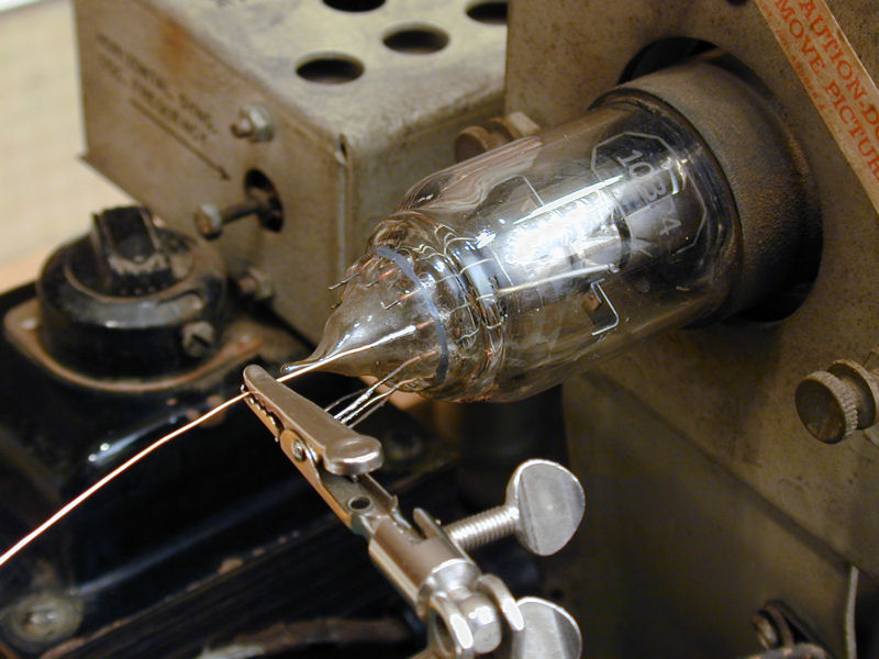
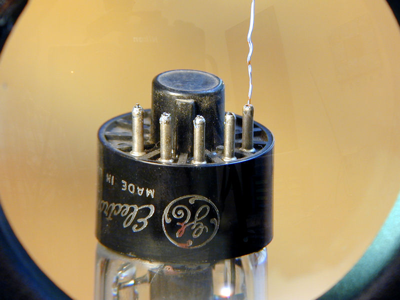
The next photo shows my first attempt at soldering a new lead to the stub. I had
first scraped the stub shiny with a razor point and cleaned it with soldering flux
to improve adhesion. (In hindsight, I should have used a thinner strand of wire,
rather than one that approximated the gauge of the original leads; a thinner
wire will bend under stress before it breaks the joint.)

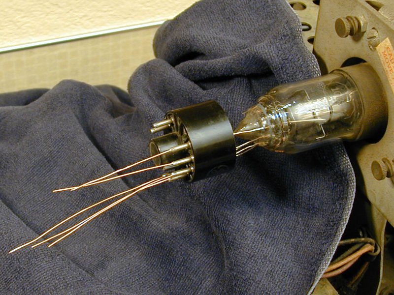
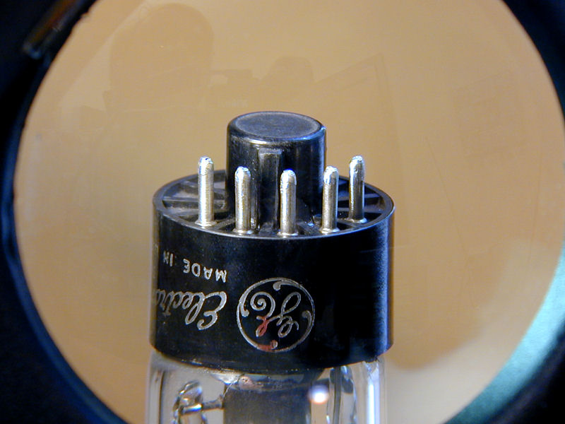
So far, so good. In the following photo, I have attached guide wires to the other leads
and begun to slide the base cap onto the tube end. At this stage, the new lead was
electrically connected and I got the same strong results on my CRT tester.

Alas, the joint broke loose when I gently wiggled the cap into place. The surrounding
glass makes a very effective heat sink, so perhaps this was a "cold"
solder joint, sufficient for an electrical connection but lacking the adhesion
needed for a lasting bond.
The experiment taught me two things: ordinary solder won't work here, and that
heavy un-stranded wire is too stiff. Following the advice from VideoKarma folks,
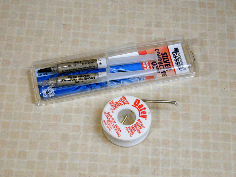
I ordered some silver-filled epoxy and found a roll of silver solder
used in a previous project.

The conductive silver epoxy is designed expressly for electronic repair, such
as fixing broken printed-circuit boards. It doesn't come cheap: these little tubes
contain about 1/3 ounce of epoxy and they cost $31. Still, that's much less than
it would cost me to buy a new, strong 10BP4 tube.
I removed the stiff guide wires from the original leads, re-cleaned the stub, and then
carefully silver-soldered a double twisted strand to it. Without disturbing the wire,
I applied silver-filled epoxy around the joint and let it cure overnight under low
heat.
Before trying to attach the cap, I re-tested the tube to confirm that the repair
was successful. As one forum member pointed out, the grid doesn't carry much
current, so even a small electrical pathway should be sufficient.

I initially tried soldering new guide wires to the other leads, but this
was tricky, since you need to make a butt joint rather than wrap
the new wire around the lead, which would make it too thick to fit through
the pin. Instead, I carefully straightened the old leads and adjusted their
spacing to fit the cap precisely, holding the cap pins next to them as a guide.
Then it was simple to slide the cap on.
In the next photo, I have installed the tube base over the leads. You can see
the new stranded lead sticking out of pin 10.

To remove old solder from inside
the pins, I simply heated each one and then rapped the cap on the workbench. After trying
the fit, I partly removed the cap, squeezed some RTV "sensor safe" sealant
inside, pressed it onto the CRT neck, and then let the RTV cure for a few hours.
The next photo shows the final repair, after the leads have been trimmed
and the pins have been re-soldered.

Whew! I had been nervous about this repair, but it proved to be
simple. It's still possible that the joint will fail under the stress of
heating and cooling during normal use. That would be more worrisome if it
were attached by nothing but a miniscule dab of solder. With the
reinforcement of conductive epoxy, I'm hoping it will last a long time.
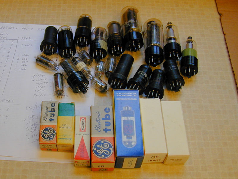
Gathering Parts
With CRT repair out of the way, I began collecting the parts needed
for this project. In addition to the usual
capacitor replacement, I needed to supply over two
dozen tubes.
Digging deep into my tube stash, I came up with 21 of the 28 needed
small tubes. The seven additional tubes in boxes were ordered by mail,
as were new caps.

Now I could populate the chassis. The tube socket holes were probably dirty
from sitting empty for years, so I wiped each tube's pins with DeOxit before
insertion and then unplugged and plugged the tube several times. Now
our little Capehart is looking more civilized!

The previous photo shows a slightly different view of the tuner than previous
shots. It's mounted at an angle to avoid bumping the bell of the picture tube.
Remember, this same chassis was used in a tabletop cabinet, so keeping it narrow
made sense.
If you are ordering capacitors for one of these TVs, note that the service manual's parts list
doesn't include every part in the chassis. It's more of a price list. While it lists every
type of component used in the TV, it didn't list their quantities, as
many service manuals do.
Thus, the parts list shows a Part Number 90, a 30/30/20-mfd multi-section electrolytic can.
If you look at the schematic, however, you see that Part 90 is used at three
different places on the chassis, so to replace those three cans, you need nine
capacitors, not three.
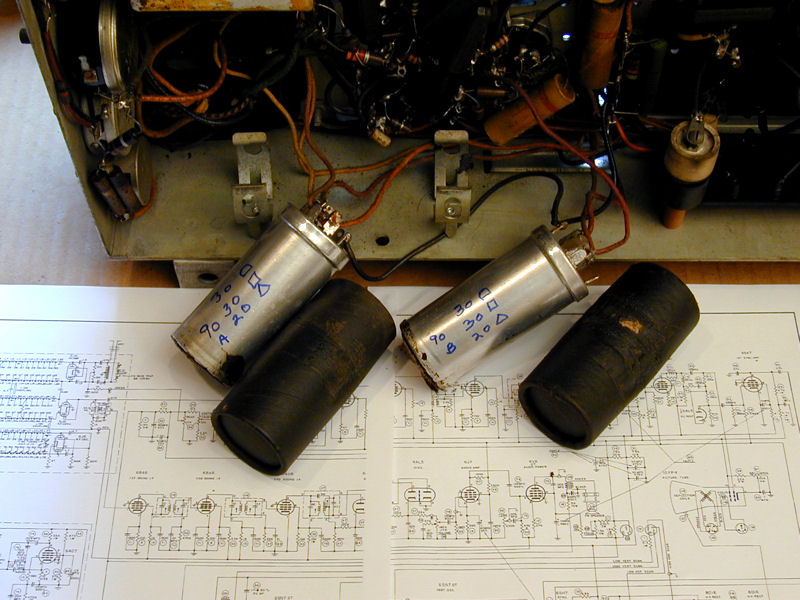
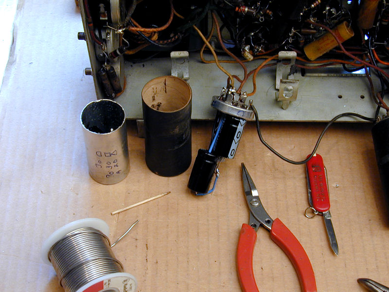
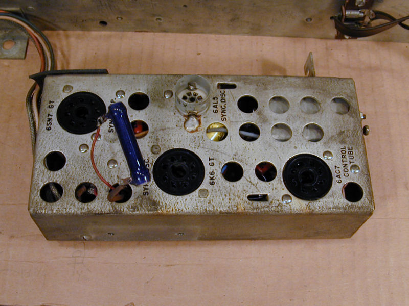
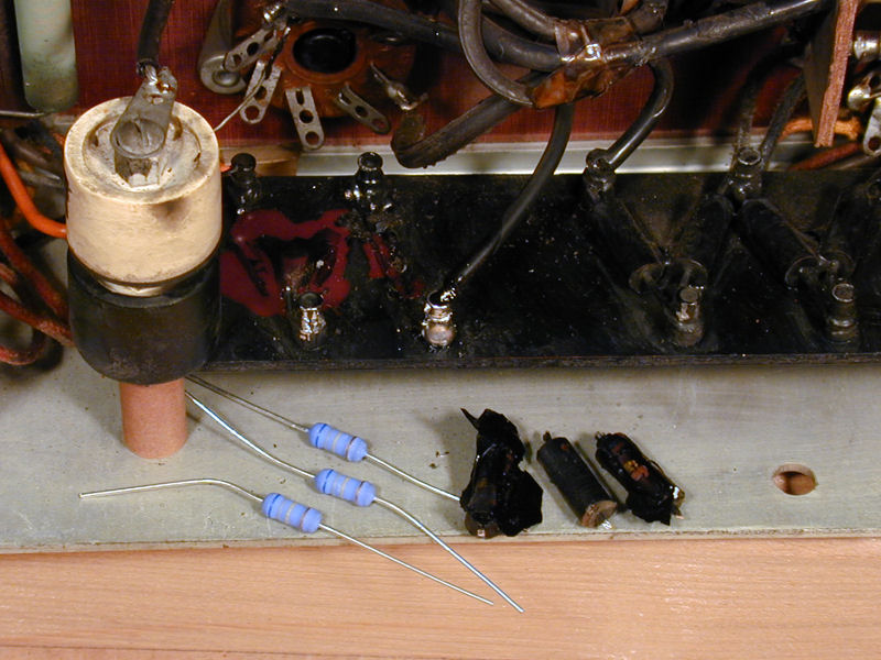
Replacing Electrolytic Capacitors
Since capacitor replacement is a common procedure, I'll refer you to my
recapping article for the basics. The next photo shows
two of the Part 90 type electrolytics.
To keep things straight, I named the three
cans 90A, 90B, and 90C, marking each with that name on the schematic.

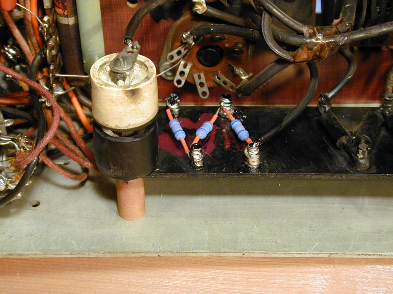
Here, I'm restuffing the original containers, installing the new
caps on the old bases without unsoldering all of the leads. You can read
more about that technique in my
RCA CTC-7 article.


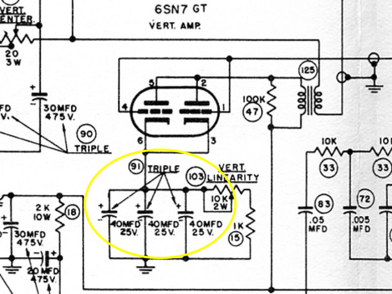
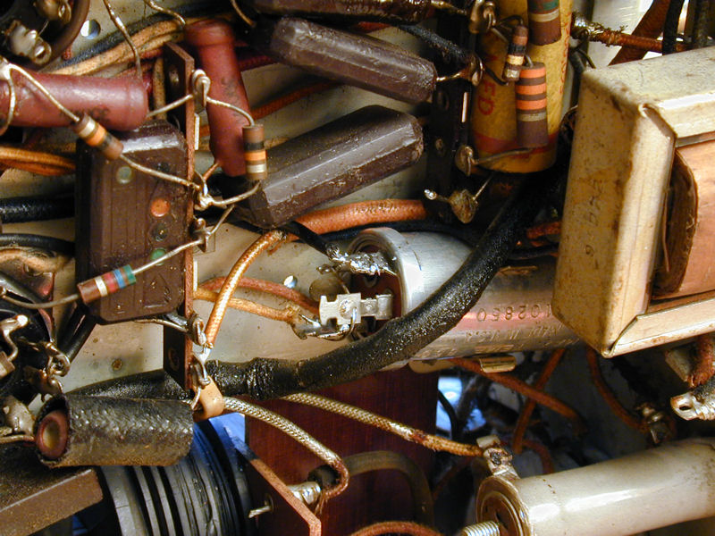
Capacitor 91 is another multi-section electrolytic in a can, comprising three
40-mfd capacitors rated at 25 volts. The schematic shows its positive leads
connecting to the cathodes of the 6SN7GT vertical amplifier tube.


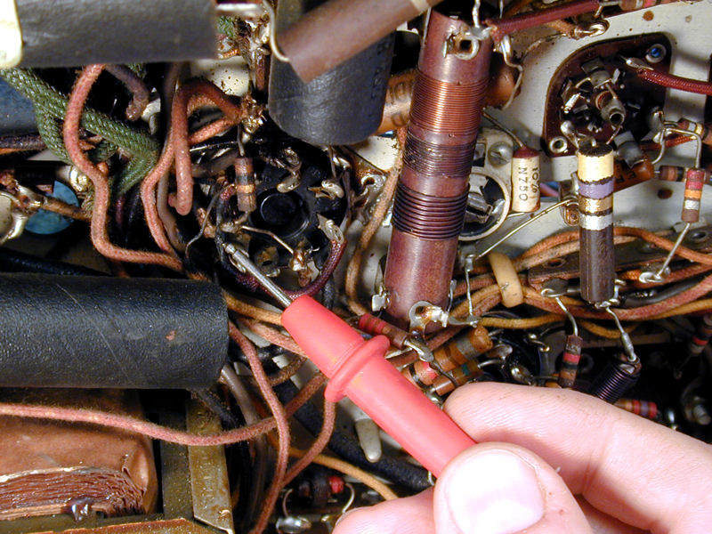
As often occurs with schematics, parts close together in the logical diagram
may be far apart in the physical layout. The vertical amplifier tube is on the opposite
end of the chassis from this can. Tracing Part 91's positive lead to that socket,
I found an ugly sight. These leads were badly burned. One of them lost its insulation
completely. Perhaps one or more of these capacitors suffered a short circuit.

I made a note to check the other components connected to that tube's
cathodes: the vertical linearity potentiometer (Part 103) and a
1K resistor (Part 15).
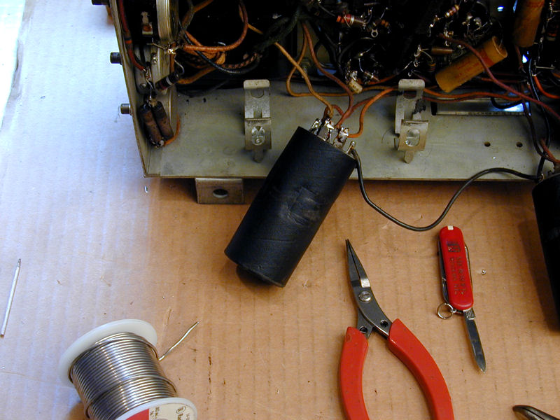
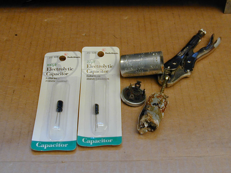
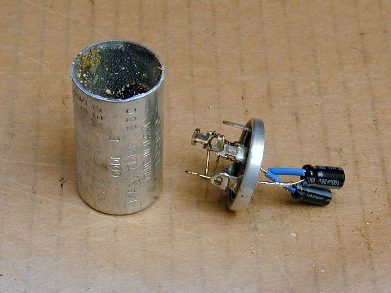
The Part 91 can holds three 40-mfd capacitors wired in parallel,
which equals a single 120-mfd cap. Using parts I happen to have on hand, I'll
replace them with a 100-mfd cap and a 22-mfd cap wired in parallel (both are rated
for 35 volts DC). The rightmost photo shows the restuffed can, wired into
place and ready to go.


The leftmost photo shows the old capacitor innards pulled from the can.
In a healthy capacitor, this material would be moist and fresh, completely
filling the can, not a shrunken, dried out carcass. It's unlikely
that the TV could have worked properly with that junk part in place.
You might wonder why Capehart used this can containing three capacitors,
since they are paralleled to act as one cap. Economy is
my guess. Perhaps they got a great deal on a carload of 40-40-40 cans,
or the Capehart-Farnsworth factory used the same can in more than one radio or
TV model, either as a single 120-mfd cap, an 80-40 can, or a 40-40-40 can.
In any event, my replacement will work just like the original.
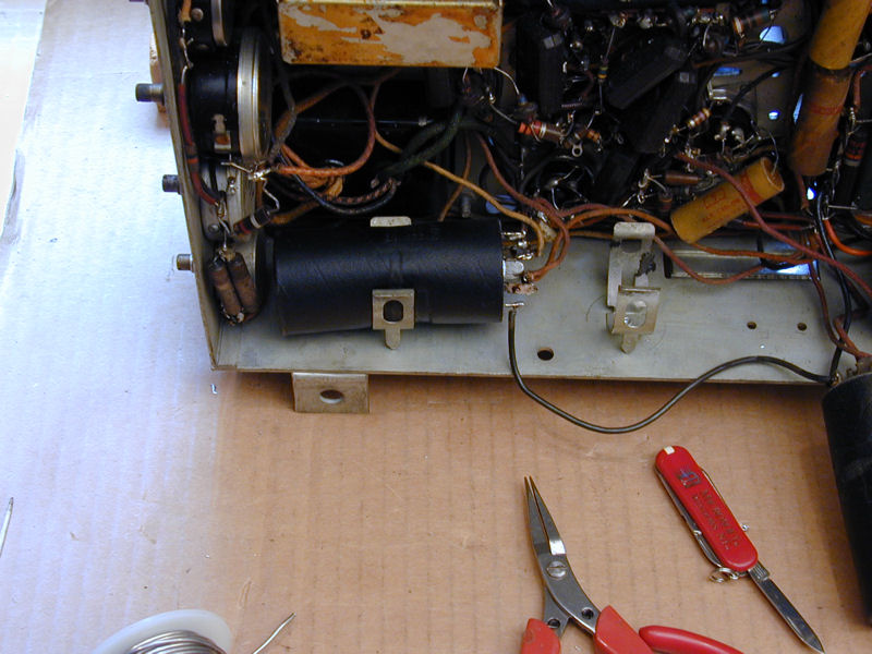
That concludes the quick 'n easy portion of our program. When I saw how
the next two cans were hidden under the horizontal AFC subchassis, my first reaction
was, "You've got to be kidding!"

Fortunately, the subchassis is connected by flexible cables.
In the next photo, I have loosened its wing bolts, swung it aside,
and then removed its support bracket from the side of the chassis.
(You can also detach the subchassis completely by unplugging its cable
from the main chassis.)

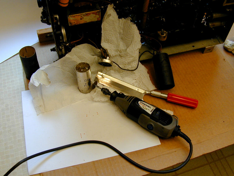
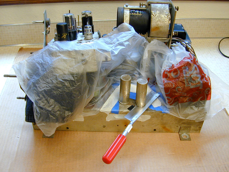
Sawing the cans takes less time than taping and masking the area.

Installing the replacements will be easier if I mount the chassis on the stand that I
built to hold my
DuMont RA-113 on the workbench. Sturdy
bolts run through the chassis' own mounting holes, securing it to the stand.

Each of these cans contains three electrolytics. Part 89 has three 10-mfd/450v
capacitors, while Part 93 has two 500-mfd/10v caps and one 40mfd/10v cap.
After installing the new caps, I took photos from underneath to show the can bases all wired up.
The can for Part 89 was too small to hold all three new caps, so I wired one separately under the chassis.
I also needed to swing aside the big cardboard-coated can capacitor and temporarily remove
the white and black "doorknob" capacitors from the high-voltage doubler board.


That part of the chassis is so crowded that I couldn't have fit all of
the new electrolytics directly underneath. Simply reaching the cans' terminals to
solder the new connections was rather challenging.
Much later in the project, after hours of playing on the workbench, I was
satisfied that the new capacitors worked reliably. I reattached their
cans with two-part epoxy, temporarily holding them in place with a few
licks of tape.

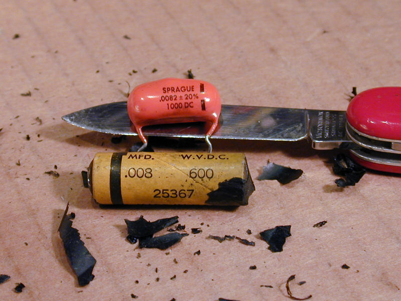
Replacing Small Capacitors
Replacing the small non-electrolytic capacitors was straightforward,
with a couple of exceptions. If the underside of the main chassis seemed
crowded, it couldn't hold a candle to the horizontal AFC subchassis.
In the first photo, I have flipped over the subchassis and removed
its bottom cover. This small space contains twelve (!) paper capacitors. The
second photo shows the subchassis after initial recapping, which opens up more
elbow room.


Three hidden capacitors are easy to overlook. The first is above the chassis,
concealed by a shield over the volume control. I removed the shield and
set it aside for this photo:

The second hidden cap is in the same area, but underneath the chassis.
We saw this spot earlier when restuffing an electrolytic can (first
photo). The .05-mfd molded paper cap can't be seen until you remove the audio
output transformer (second photo).

There's no need to unsolder anything from the audio transformer. Simply
remove its mounting screws and swing it out of the way while replacing that capacitor.
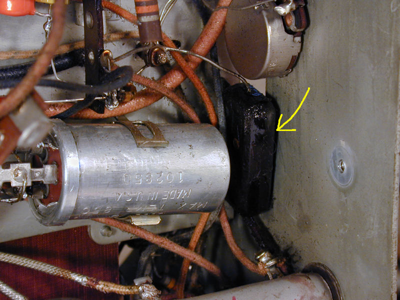
Hidden in a different way is this paper capacitor on the high voltage board.
Painted with black insulation, it's easy to miss unless you're carefully
reading the schematic and checking things off. I happen to have a 1000-volt
rated cap on hand that will be more than adequate to replace it.


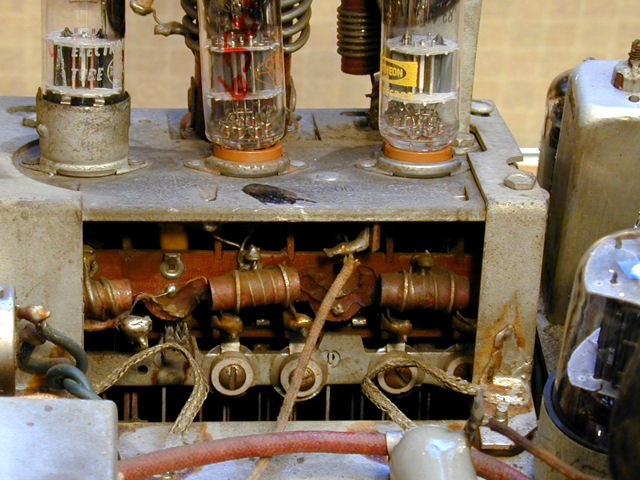
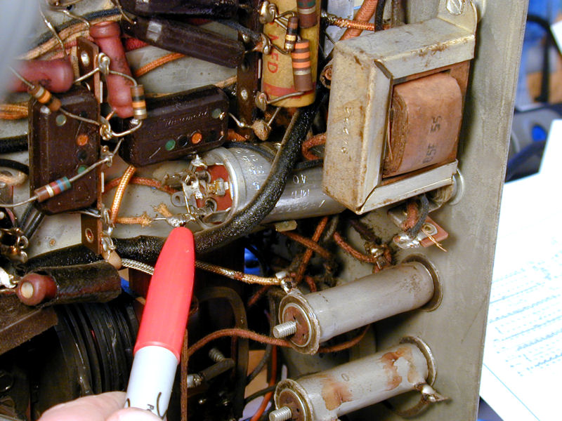
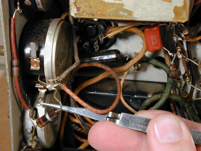
Replacing the Ruined Width Control
I had earlier noticed signs of overheating, including burned wires
and a couple of components whose leads had either burned or broken off.
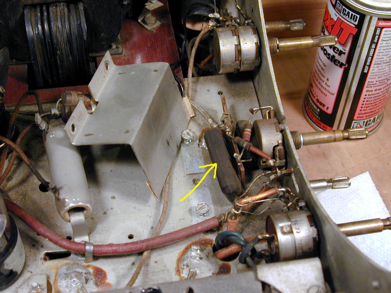
While inspecting for other damage, I noticed that the Width potentiometer
had wires connected to only one terminal—the middle, or wiper, terminal.
In the next photo, I'm pointing to the empty terminal where something obviously was
connected before.

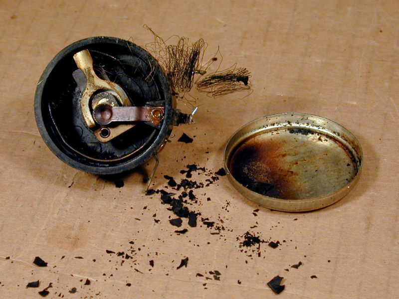
When I turned the control, it made a scraping sound inside. I opened it
to learn that its wirewound resistive element was ruined, clearly the
victim of a meltdown:
No chance of repairing something like this. I ordered a replacement and continued
checking controls and resistors.
A glance at the schematic (yellow oval) explained why the repairman had moved
one of the leads from the end terminal of the potentiometer to the middle. This
bypassed the potentiometer, taking it out of the circuit.
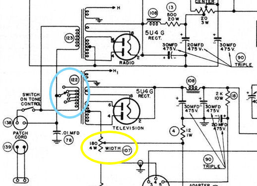
With that modification, the width was not adjustable, but at least the television
would operate.
Charred remains like this send up a red warning flag. Parts don't burn up for
no reason! As I continue this project, I'll look for what caused
this catastrophic failure.
Resistors and Other Bad Stuff
This set uses lots of power resistors, and a few of them were bad. This photo
shows a wirewound resistor on top of the horizontal AFC chassis. The old one
was open; this replacement will stand vertically as soon as I put in its mounting
screw.

Mounted on the phenolic board for the high voltage doubler are two chains of
resistors. My DuMont RA-113 uses a
similar doubler circuit. In this TV, the 680K resistors in one chain had drifted
far beyond the specified value, so I replaced them:


Everything on the doubler board, including these resistors, was coated with insulating paint to
reduce corona from high voltage. Another corona-reduction strategy, which you should follow when
replacing parts here, is to make all solder joints smooth, with no spiky protuberances.
I might recoat the board with corona dope after I'm satisfied
that the HV circuit works correctly.
I generally try to avoid "shotgunning" (unnecessarily
replacing) resistors, which are more reliable than capacitors.
In this set, however, the closer I looked, the more bad ones
I found.
I paid special attention to the horizontal AFC subchassis, whose circuits
demand precision. I had heaved a sigh of relief after replacing a dozen capacitors in
that cramped space. It would have been wiser to check all of its resistors,
then, too. By the time I finished this second pass, I had replaced about a
dozen resistors, leaving only a few original parts in the
subchassis other than the transformer and tube sockets:
Before powering up, I did another round of testing, relying on the resistance chart
in the factory service manual. This uncovered more sketchy resistors.
First Power-Up
At last, I was ready to try the set, using a metered variac to
monitor how much current it drew. The picture tube displayed a raster,
suggesting that my CRT repair had succeeded.
This is not a coherent screen image, but a few things are working.
The low-voltage power supply is providing heater and B+ voltage,
and the high-voltage power supply is making enough juice to light
the screen.
In addition, with a signal source connected, I could hear faint audio
from the speaker. This told me that the tuner and audio sections
worked, at least marginally.
This trial lasted only a couple of minutes, long enough to observe the
screen and make some basic voltage checks.
I noted with dismay that the TV drew more than 360 watts, well over the
specified 300 watts. One common cause for this would be
a short circuit in a power transformer (bad news, if true).
The screen was also very dim, suggesting inadequate high voltage,
which in turn might mean a defective flyback transformer (worse news, if true).
To add to my worries, when I turned the TV back on for more checking,
the raster and audio disappeared.
Get Busy, Sherlock!
Musing over ugly possibilities, I pulled the plug and
put my detective hat back on. The evidence of a past meltdown, combined with
excessive current consumption, made me loath to reapply power until I
had thoroughly examined the TV.
First, I checked my dozens of capacitor and resistor replacements,
confirming that the right values were installed in the right places, and ticking
off each one on the schematic to ensure that nothing was missed.
Finding no mistakes, I went back to the manual's resistance chart, repeating
measurements for each pin of the TV's 28 small tubes.
In the course of these two passes, I replaced even more marginal resistors.
Checking the Horizontal Output and AFC Circuits
This TV's horizontal output circuit is a little different.
It uses a 6L6 tube where my other 1948 sets use a 6BG6. It also
has no high-voltage damper tube and no adjusters for
horizontal drive or linearity.
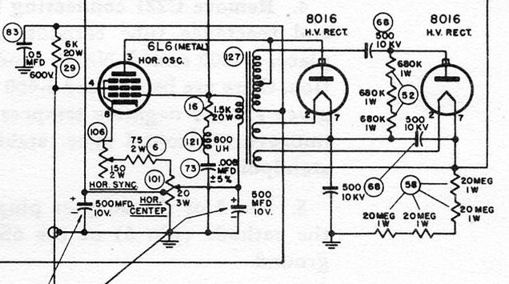
I paid close attention to every component around the 6L6 tube and I
traced continuity around and through the flyback transformer, confirming
that its windings were not open (although they still might harbor
small internal short circuits).
The horizontal AFC subchassis holds the rest of horizontal sweep circuitry,
so I went through the same drill there.
Testing the Power Transformers
In a conventional design, you could remove the horizontal output tube
and power up the set, at least briefly, for voltage checks. Since this
setup was unfamiliar, I asked the VideoKarma TV forum whether this seemed safe.
Bill (aka oldcoot88) endorsed pulling that tube and he also suggested a basic test
for the power transformers: monitoring the current draw and heater voltage
after pulling the 6L6 tube, then pulling the two 5U4G low-voltage
rectifier tubes one by one, and finally measuring the draw with all
tubes removed. Here are the results:
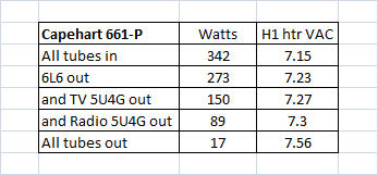
Drawing only 17 watts with all of the tubes removed suggested
that the power transformers had no shorts. Good news!
Executive summary: after hours of testing, I hadn't found any big
problems, although I had replaced a few more components as a precaution. Of course, it's
reassuring to know when things work correctly. However, the TV's heater voltage was
still too high, causing excessive current consumption.
Will The Bad Tubes Please Raise Their Hands?
While all of the tubes were out, I decided to re-test them.
They had been tested when I put them in, but as long as I had spent hours
eliminating other potential trouble sources, why not eliminate these, too?
Surprisingly, three tubes tested bad: one in the tuner, one
of the video amps, and one of the 8016 high-voltage rectifiers. Or, perhaps not
so surprising, I grumbled, since I'd scrounged pretty hard to find 21
tubes in my workshop, even borrowing a few from other sets. Those three
might have been marginal in the first place, and just happened to give
up the ghost.
No wonder my previous trial ended with a blank screen and no audio.
A dead HV rectifier means no high voltage, hence, no light on the screen.
A dead tuner tube means no signal, hence, no audio (or video, for that matter).
Our First Real Image!
I was running short of tubes at this stage, but I located
three replacements, finding fresh 1B3GT and 6AC7 tubes in my stash and
borrowing a 6J6 from my
DuMont RA-103.
After installing all of the tubes, I tried another of Bill's suggestions: using a variac
to reduce the line voltage until the TV drew the specified 300 watts, and then measuring
the heater voltage. He guessed that the correct heater voltage would be achieved with
a line voltage around 105-110 volts AC.
Bingo!
As predicted, 110 volts on the line input gave a heater voltage of 6.3 volts.
Although the horizontal frequency was initially far off, after adjusting that and a
couple of other controls, my 661-P made a real picture for the first time in
decades.
The image was stable, but problems remained in the vertical circuits:
notice the bright foldover band at the bottom, for instance. The height and vertical
linearity controls were overly interactive, too, making it nearly impossible to
get sensible linearity without distorting one part of the image or another.
Back to the workbench, where I finished replacing every last resistor
related to the vertical tubes and controls.
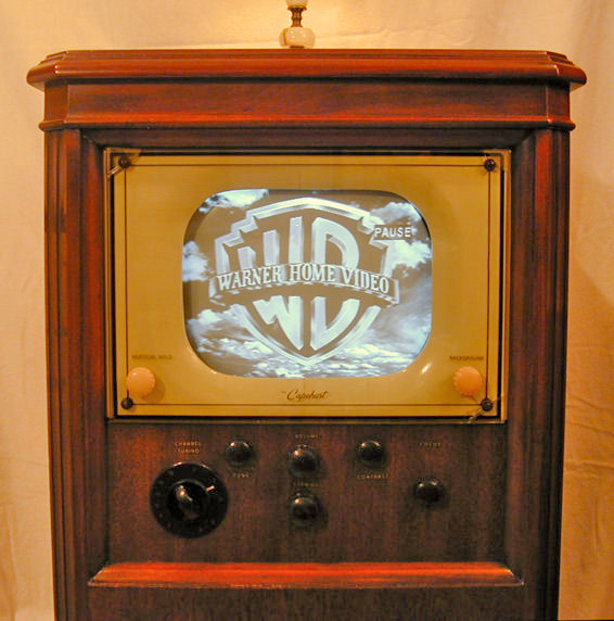
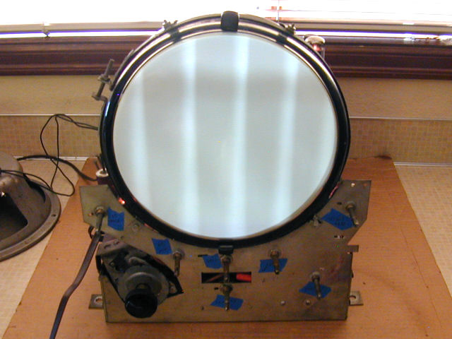
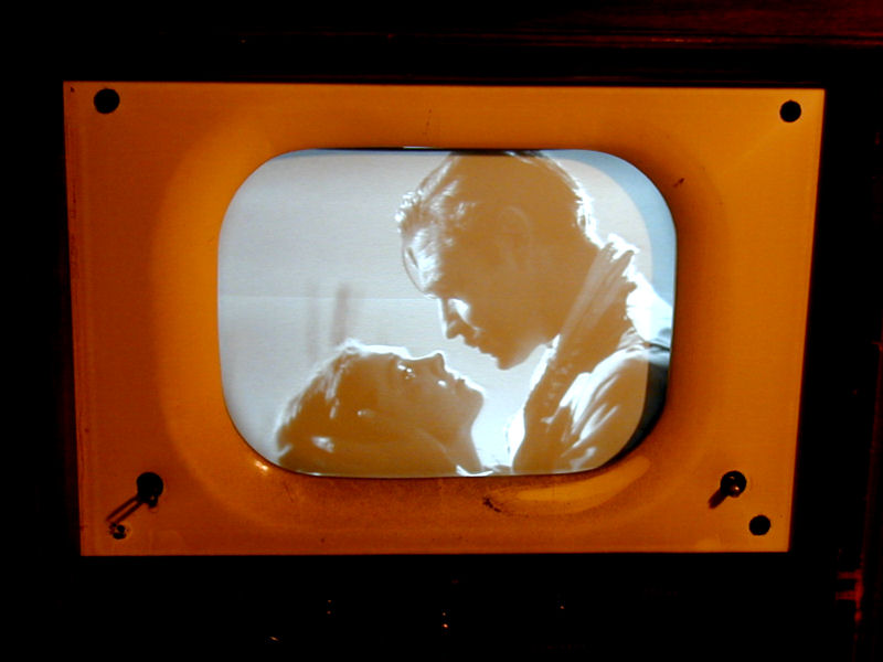
A Better Image
After those replacements, and further adjustments of the picture controls,
the image looked much better.
Now we have good contrast and brightness, with excellent focus. The vertical
foldover is cured and the horizontal and vertical stability are great.
Although the audio was initially weak and fuzzy, I improved that by carefully
tweaking the audio IF adjusters while listening to a weak signal, aiming at
maximum volume and clarity. This "bareback"
adjustment isn't as precise as following the factory procedure with a signal generator
and oscilloscope. However, the TV now has clear sound and plenty of volume, so
I'm content for the meantime.
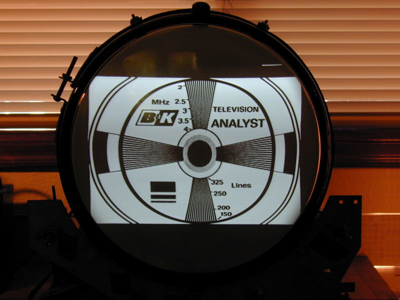
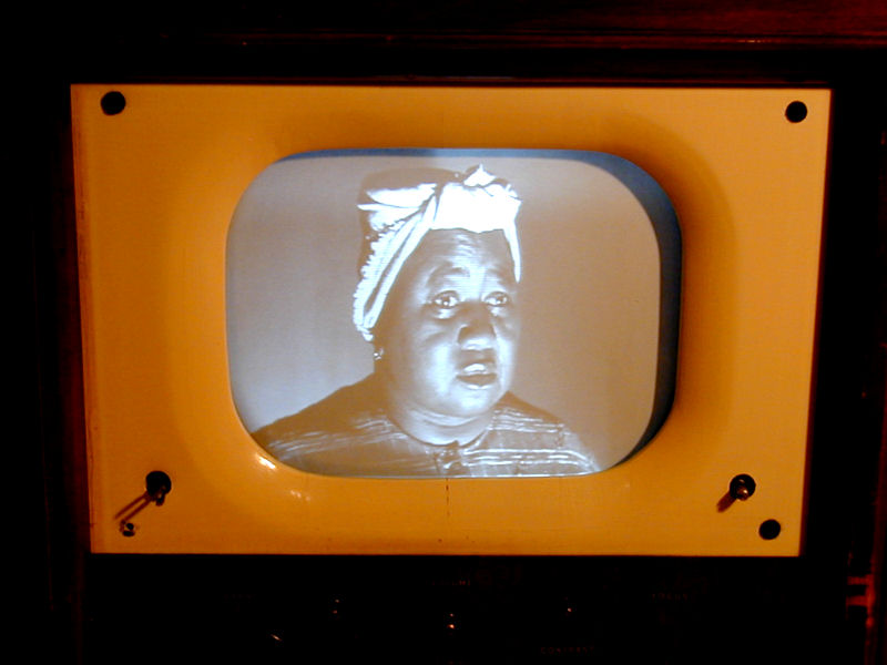
For the previous photo, I tried to adjust the height and width to fit the
small mask in the Capehart's cabinet. The vertical is correct, but
I couldn't reduce the width enough. Excessive width can be a symptom of
weak high voltage, so that remains on my to-do list.
Reducing the Line Voltage
It's clear that I can get good performance from this TV at reduced line
voltage. The question is how to manage that. The line voltage at our house
generally runs around 120-121 volts AC. With that input, the heater voltage
(hence, the entire TV) runs too "hot," drawing too much current.
The old width control was burned up and I had found other toasty remnants
here and there. While playing the TV earlier, I could feel warmth on the
chassis by the width control. I certainly don't want the control to overheat
and melt down again.
Speaking of the width control, the Capehart manual has this entry in a
list of problems and possible causes:
The TV was now playing happily and I had previously inspected the 6L6 wiring,
so that eliminated possible causes A and C, leaving cause B: breakdown of filter
capacitor and short of B+ voltage to ground.
Of all the ills that old TVs and radios can suffer, bad electrolytic
filter capacitors are just about the most common. I'll bet that someone fried
that width control by turning on the TV after it had sat unused for years and
the power-supply filter caps had dried out.
There are various ways to reduce line voltage. I could use my variac, of
course, but I need it for everyday use, so that's not ideal.
I could also build a humbucking transformer and plug
the set into that, but I didn't have the necessary parts on hand.
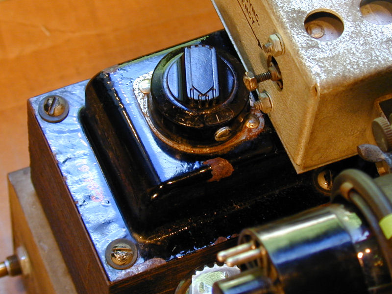
While thinking about this, I remembered that one of the
power transformers (labeled Television in the manual) has
a voltage switch on top.

The manual calls this the voltage selector and it specifies the line input as
a range from 105-120 volts AC. Clearly, the intent is to let you adjust for different
line voltages. This schematic of the low-voltage power supply shows
the voltage selector on the Television transformer (blue oval):
Looking at my voltage selector, I surmised that it was on the lowest setting,
for 105 volts. If I switched it to 120 volts input, that should reduce the transformer's
output and solve the problem!
Unfortunately, I couldn't get the switch to budge, after removing its
setscrew. It couldn't be turned, pulled upward, or moved at all. Perhaps it had
never been moved since 1948 and now it's stuck for good.
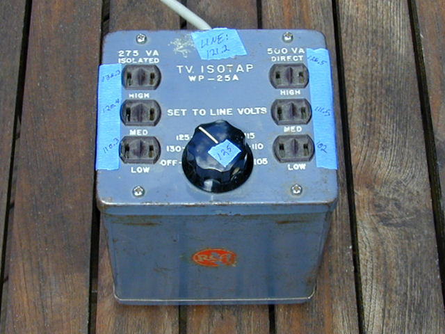
Then I remembered another item from the workshop: an old RCA
"TV Isotap" that I bought at a swap meet years ago.

Built for TV service, the Isotap lets you change your incoming line voltage
to different AC voltages and it provides both isolated and direct outputs.
In the photo, I had marked our house's line voltage at the time, 121.2 volts,
and the voltages available at the Isotap's plugs when its switch was set for an
incoming level of 125 volts.
Problem solved! I almost never use the Isotap (a variac is more flexible), so I
can leave the 661-P plugged into it indefinitely, using an output
that approximates 110 volts.
Mid-Course Status Check
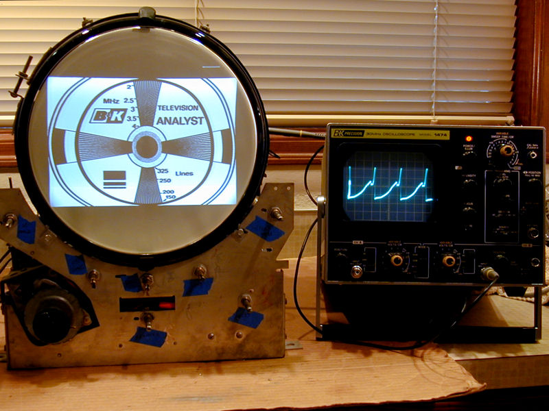
At this stage, I'm satisfied with most of the electronics, but
The horizontal linearity isn't perfect. The test pattern shows how
the left half of the image is stretched relative to the right half.

This degree of non-linearity isn't very noticeable in everyday viewing, and,
given that the TV has no horizontal linearity adjuster, I may
have to live with it.
Since the horizontal AFC system was a little unfamiliar, I was curious to see
what sort of waveform it produced. This photo shows the sawtooth waveform that
is fed to the 6L6 output tube:
It's a very stable waveform and the horizontal lock is rock solid. The
designers were so confident in this system that they didn't provide a
horizontal hold control on the front of the cabinet, and in fact, none
is needed in everyday viewing.
The only front horizontal control is the Framing control, which lets you
adjust the horizontal centering. This is in addition to the centering control
on the rear apron, so I'm a little curious why the designers provided it
in front. Centering is not something you need to adjust every day, and
this TV has outstanding horizontal stability.
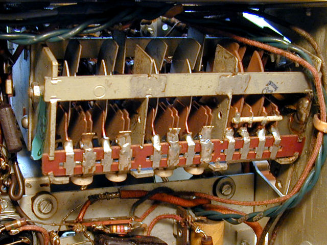
Tuner Mechanism
As noted earlier, this television's tuner uses air variable capacitors
with mechanical detents. These photos show the tuner from below and from
one side.
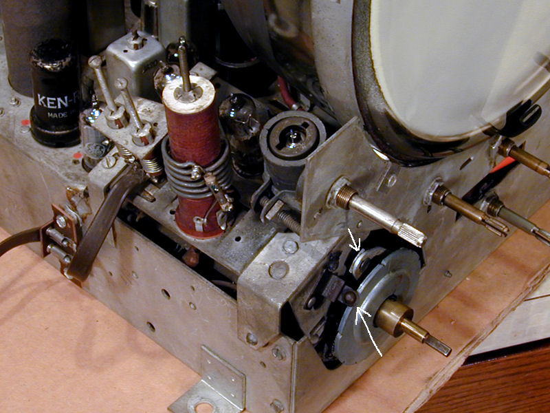
The following photo shows the detent mechanism. The lower yellow arrow
points to a spring arm with a ball that clicks into little slots
on the disc edge, securing the tuner at the right spot for each station.

The upper yellow arrow points to a hinged lever connected to a
"clutch" that's mostly hidden inside the tuner. This switches
between the low VHF stations (2-6) and the high ones (7-13). As you may
know, the VHF television band has a gap between stations 6 and 7, which
is partly occupied by the FM radio band from 88-108 megahertz. When you move
the tuner between channels 6 and 7, the clutch automatically switches
between the low-channel and high-channel ranges, skipping the FM radio
band entirely.
It's interesting to compare this tuner to those in my
DuMont RA-103 and
DuMont RA-113.
DuMont made a virtue of the fact that their continuous tuners
covered the FM radio band, providing radio reception as
a "free bonus" integral with the television.
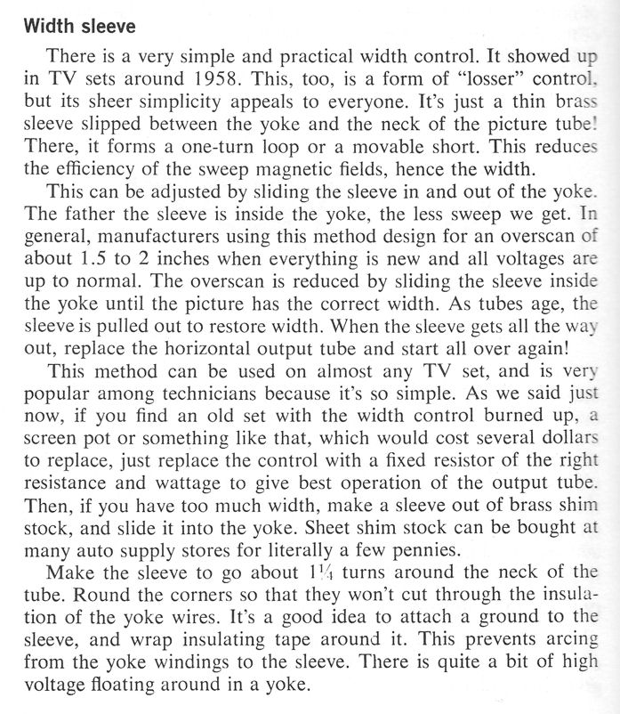
Experimenting with a Width Sleeve
Earlier in the project, I had been unable to reduce the width enough
to fit the CRT mask. Bill suggested trying a width sleeve,
which was a new concept to me.
I found an explanation in an old TV service book:

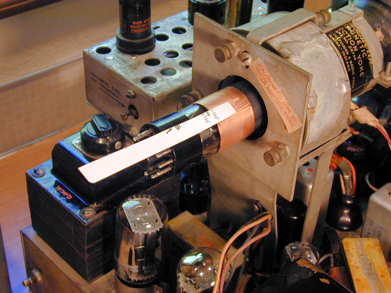
I cut a strip of copper foil, rolled it up, and taped on a cardboard arm,
so that I could slide it in and out of the yoke after
reinstalling the ion trap magnet and CRT socket:

Just as advertised, the sleeve was effective in reducing
the sweep field. So effective, in fact, that I could block the sweep
completely by sliding it in only a short way.
Clearly, that sleeve was wider than necessary, and there was so little
clearance between the yoke and the CRT neck that sliding it was extremely
tricky. I cut the sleeve down:

This narrower sleeve's electronic effect was less drastic, but it was even
more difficult to slide. The soft foil bent easily and got stuck at the
slightest obstruction. No doubt a stiffer metal would work better, but I had nothing suitable
on hand, so I tabled the experiment for the time being.
Later in the project, when I prepared to reinstall the chassis in the cabinet, I
made the final round of tweaks, including adjusting the yoke. Now,
I was able to set the width without any extra tomfoolery. I'll remember
the width sleeve trick in case I need it in a future project, however.
The biggest difficulty in this case resulted from the type of
ion trap magnet
used by Capehart. It's a wide collar that has to be pretty close to the yoke
for optimum brightness. This scheme would work better with a CRT that uses
a different style magnet, or no magnet at all.
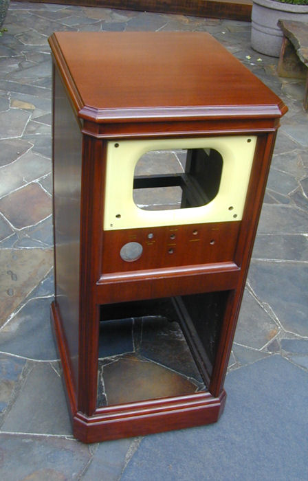
Cabinet Restoration
After puttering with the electronics for weeks, I finally turned my
attention to the cabinet.
Safety Glass
First order of business: removing the CRT safety glass and cleaning the mask. Here
are before and after photos. In the first photo, notice how much sooty dust I had disturbed
with one light finger wipe. The soot came off easily, using clear water and a damp towel.


From casual inspection, I had assumed that the mask was a piece of
butter-colored plastic behind the safety glass. In fact, it is amber paint
on the wooden cabinet, whose cutout opening has gently rounded
edges.
After cleaning the glass, I reinstalled it. For the first time, I can see
the TV working in its cabinet with knobs in place.
Before replacing the glass, I made a high-resolution scan of it.
The painted lettering and pinstripe lines are in perfect condition, but
it has little cracks in two corners of the glass. With a scan in hand,
it would be possible (although difficult) to make a replica
if I can't live with the cracks.
Calling in the Pros
After taking a closer look at the cabinet, I decided to turn it over
to a professional. I have done worse cabinets than this one,
but I don't enjoy refinishing as much as the electronic work, and
when I'm not having fun, I tend to get impatient and cut corners.
I removed the back cover, safety glass, and speaker board, and then
brought the cabinet to
Michael Mueller
in Seattle for a facelift. A short
time later, the cabinet was back, looking like new. Thanks, Michael!
Final Assembly
Now for the most enjoyable part of every project—putting the restored
chassis back into the refinished cabinet. Here's the chassis, ready to go.
Incidentally, after taking these photos, I substituted a metal 6L6 for the
glass 6L6 horizontal output tube I had been using. The manual specifies a
metal tube, but I found no perfomance difference between glass and metal,
although swapping tubes (not surprisingly) required readjusting the
horizontal frequency.
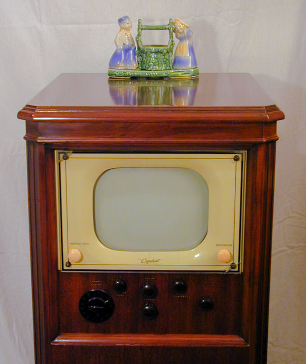
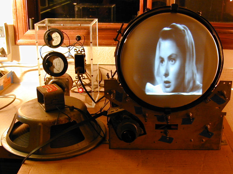
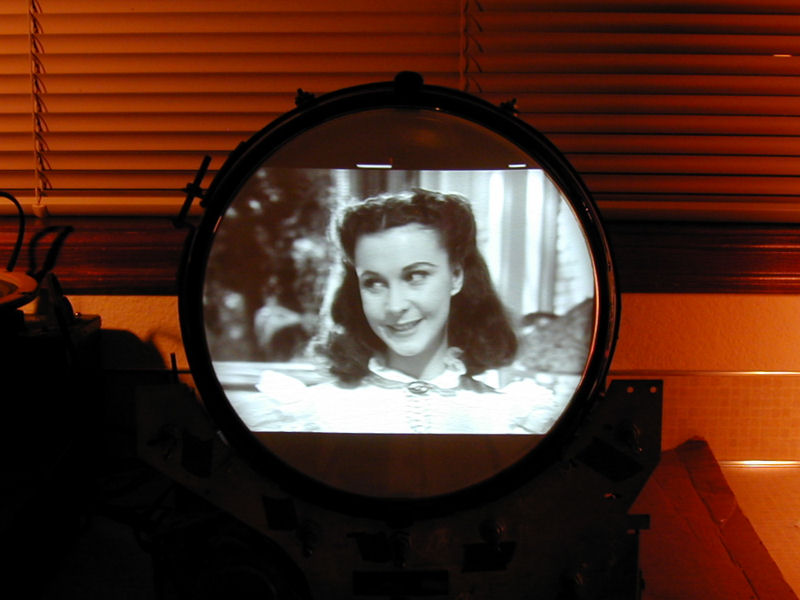
Here are some photos of the finished project.
The audio quality from the 12-inch Capehart speaker is very nice, and I appreciate
having a tone control, a rather unusual feature in such an early television.
Here's a brief video clip showing the TV in action. The sound quality from
my video camera leaves much to be desired, but at least you can tell
that the whole thing works.
Final Thoughts
This was an enjoyable project. Repairing the CRT was simpler than I
expected. The cramped chassis was not a joy to work on, and I ended up
replacing more components than usual, but the final result was very gratifying,
and there's some intriguing history behind this television.
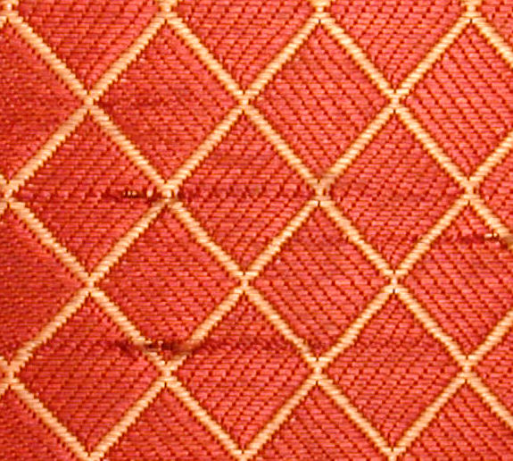
I would like to replace the grille cloth, which has some scrapes and
a stain that I wasn't able to wash out. Here's a close view of
the pattern, which has 1/2-inch squares.

I haven't found a decent match with any of the usual suppliers, so if anyone
knows where to find a suitable replacement, send me an email.
The original color is a darker maroon, as I could tell by removing the speaker
board and inspecting the edges that were protected from UV fading.
|


