Westinghouse Model H-181 Television (1949)


This Westinghouse model H-181 television looks older than it is. The TV was
made in 1949, but its highboy style cabinet
would look right at home with many console radios from the 1920s and 1930s.
I bought this set at a sale to benefit a local charity. I could tell from
their photos that it's actually a Philco model 48-1001, repackaged and
sold by Westinghouse. This flyer from
TV History
shows the H-181 along with other 1948-1949 Westinghouse models.

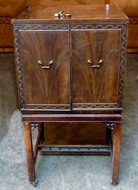
Our first photo shows the cabinet with doors closed.
It is weathered and scratched but it should look great after refinishing.
Notice the matched veneer on the doors. The decorative trim is fret-sawed and
glued around the door's edge. A decorative cross rail and fretwork corner braces
add interest to the base.
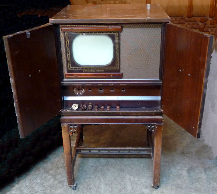
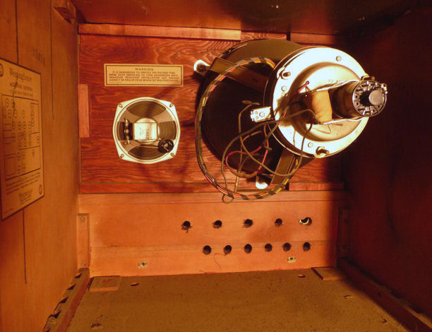
Next, the console with doors open.
All of the original knobs are present, although I had removed them when
this shot was taken. The inside
shows the cabinet's original color, a medium, slightly reddish mahogany.
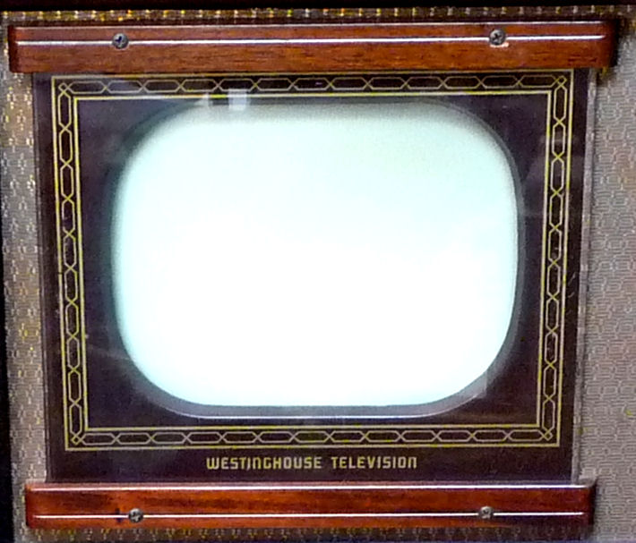
The round 10-inch picture tube is mounted behind a gently rounded rectangular mask.
Two mahogany strips hold the reverse-painted safety glass.
The top row of controls is for the user:
Tuning, Background, Contrast, Volume, and Off-On/Tone. Below them,
concealed behind a removable wooden panel, are controls for the technician: Focus, Vertical
hold, Horizontal hold, Height, and Vertical linearity.
This television's
service manual
is shared with the Philco 48-1001: Riders pages 1-17 through 1-22 and 2-81 through 2-86.
Thanks to the
Early Television Foundation for hosting
this and other television schematics.
The electronic design is pretty conventional for the time. The H-181 uses
"split sound" audio, which you can read about in my
RCA 630TS article. Two 5U4G rectifier
tubes are used in the low-voltage power supply. One 6AT6 tube is used for
DC restoration, a feature that improves rendition of dark areas in
high-contrast scenes.
The H-181 uses 27 tubes:
| Tube |
Type |
Function |
| V1 |
6AG5 |
RF Amplifier |
| V2 |
6AG5 |
Mixer |
| V3 |
6J6 |
Oscillator |
| V4 |
6AG5 |
1st Video IF Amplifier |
| V5 |
6AG5 |
2nd Video IF Amplifier |
| V6 |
6AG5 |
3rd Video IF Amplifier |
| V7 |
6AL5 |
Video detector / AGC Rectifier |
| V8 |
7B6 |
AGC Amplifier |
| V9 |
6AG5 |
Video Amplifier |
| V10 |
7C5 |
Video Output |
| V11 |
6AT6 |
DC Restorer |
| V12 |
7H7 |
1st Audio IF Amplifier |
| V13 |
7H7 |
2nd Audio IF Amplifier |
| V14 |
6AL5 |
Ratio Detector |
| V15 |
7B4 |
Audio Amplifier |
| V16 |
7B5 |
Audio Output |
| V17 |
7B5 |
Sync Separator |
| V18 |
7F8 |
Sync Amplifier |
| V19 |
6SL7GT |
Horizontal Oscillator |
| V20 |
6BG6C |
Horizontal Output |
| V21 |
5V4G |
Horizontal Damping |
| V22 |
6SL7GT |
Vertical Oscillator / Discharge |
| V23 |
6K6GT |
Vertical Output |
| V24 |
1B3GT |
High Voltage Rectifier |
| V25 |
5U4G |
Low Voltage Rectifier |
| V26 |
5U4G |
Low Voltage Rectifier |
| V27 |
10BP4 |
Picture Tube |
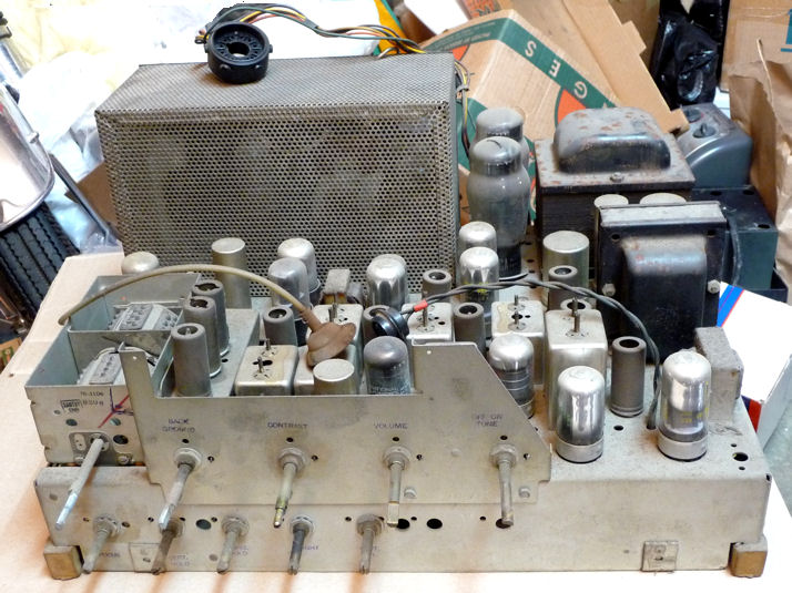
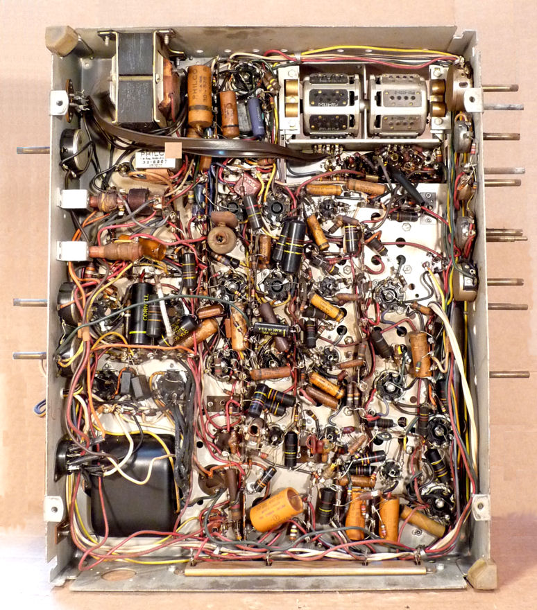
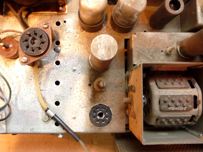
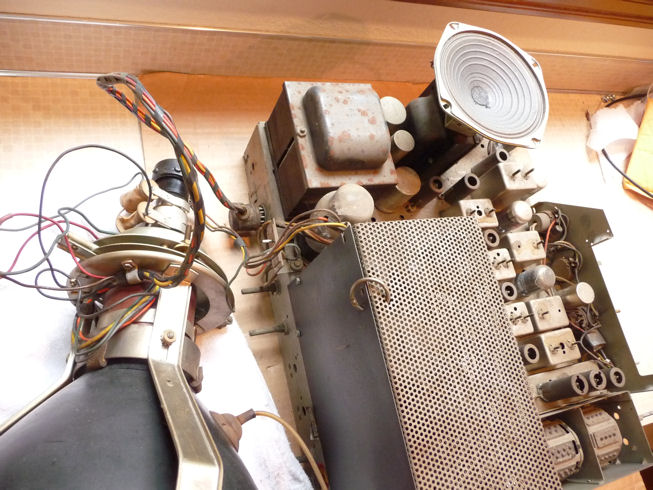
A front view of the chassis shows all of the controls. The turret-style
tuner at the left is missing a top cover, but it won't be hard to make
a new one. The big ventilated cage in the back holds high voltage components.
To its right you can see the big power transformer and smaller audio
transformer.
Like many Philco radios of the time, this television uses several "loctal"
type tubes. They're the ones with a glass top and a mirror-like inside coating,
mounted on an aluminum base. Loctals never caught on with other
manufacturers, but Philco used loads of them in the late 1940s and early 1950s.
A loctal tube snaps into the socket, making it less likely to become loose, but
its thin pins don't connect as well as conventional pins, so you should
clean loctal pins very carefully.
The picture tube socket can be seen resting on the high voltage cage,
attached to the back of the chassis by its cable. The picture tube mounts
inside the cabinet, so the chassis has no supports for it.
The rear of the chassis shows a few more adjusters for the technician.
The empty socket at lower left is for the speaker cable. To its upper
right is the place where someone tore off the original power cord, an easy thing to
replace.
The stamp "Model 48-1001" betrays this as a Philco in
Westinghouse clothing. Philco radio and TV model numbers of the time showed the year
with two leading digits, hence the 48- stands for model year 1948.
Repackaging another manufacturer's chassis was common in television's
early days, when some companies wanted to establish a market
presence before they had designed their own TVs from scratch. These
"re-badged" sets were usually sold in a slightly different cabinet.
The most frequently licensed chassis was the
RCA 630TS, which appeared
under more than a dozen different brand names.
The H-181 has nineteen electrolytic capacitors. Under the chassis we
see about forty small paper and plastic-coated caps.
Replacing sixty capacitors, give or take,
will be the most time-consuming restoration procedure.
Disassembly
After this set had waited a few months in the storage room, I needed a break
from a long-term project and decided to start on it. The
first step is to get the speaker and picture tube out of the
cabinet.
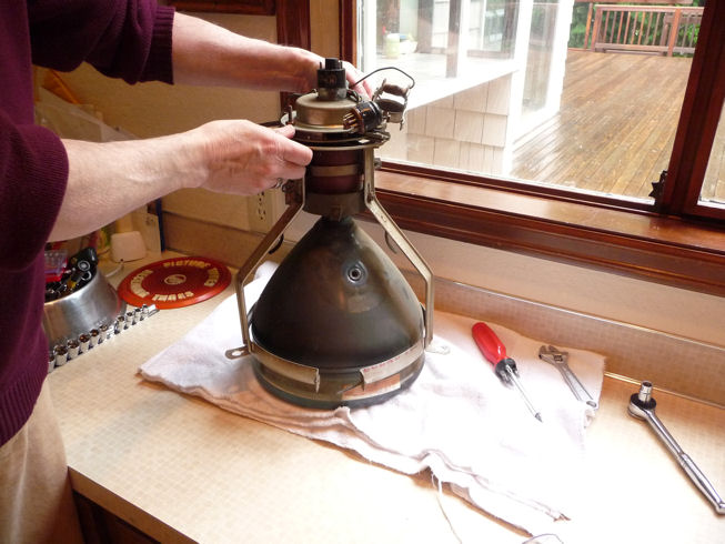
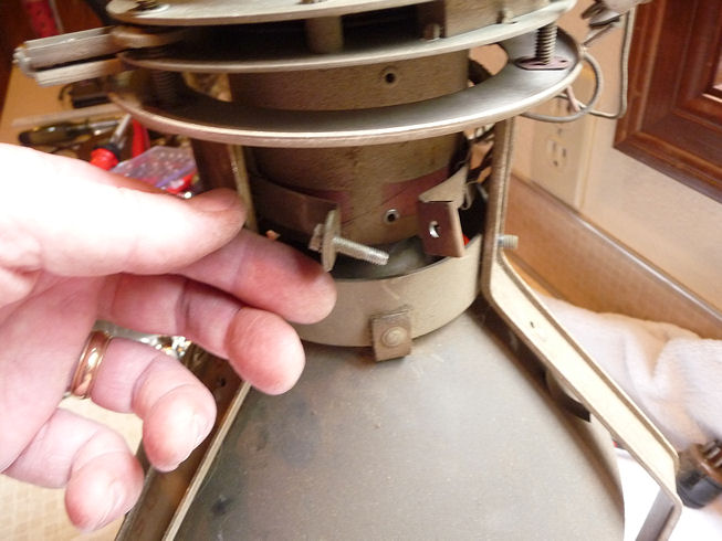
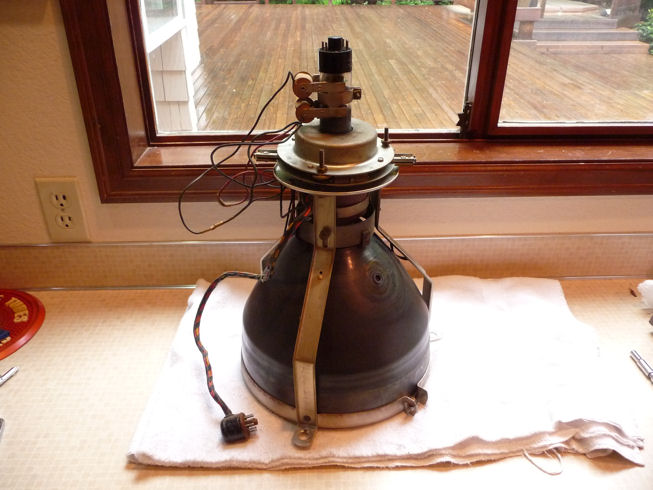
The CRT is mounted on a strong steel frame that screws into the cabinet.
The front of the frame has a retaining band for the picture tube's face
and the back holds the yoke. To remove the CRT and yoke, loosen
the three nuts at the front. Be careful not to let the tube
drop.
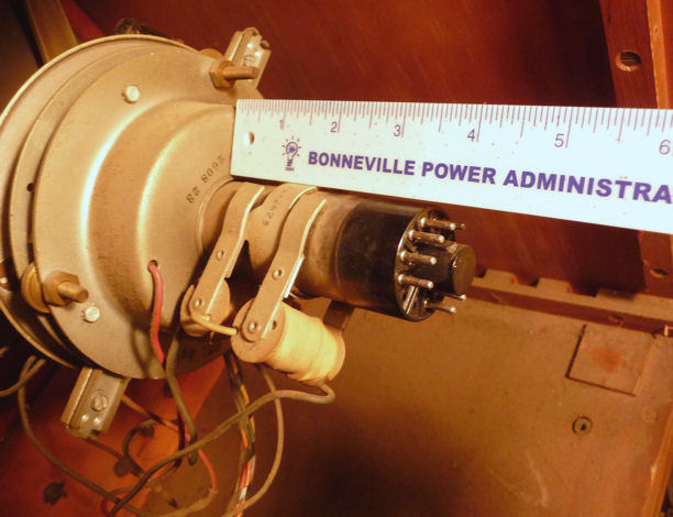
Before removing the CRT and yoke, I took this photo to show where the yoke and
ion trap magnet are positioned on the neck. The magnets are directional, so
when replacing this part, you want the same side facing forward and the magnet in
the same rotational position on the neck. If you badly mis-position an ion trap
magnet, you can make the screen completely dark even though the TV is otherwise
working perfectly.

Many different types of ion trap magnets were used over the years, with permanent magnets
or electromagnets, one magnet or two, and so on. This TV uses a two-coil
electromagnet, with the smaller coil in front.
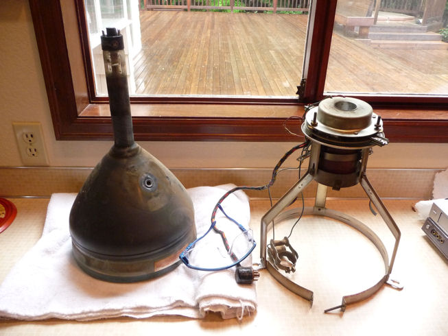
The tube and speaker are out. I wouldn't normally lay a CRT on its side, but
as long as the front retaining ring is holding the CRT bell securely, the stress
and weight are distributed through the frame, making this reasonably safe. Just
don't bump the neck or let its weight rest on the tube base.

Wear safety glasses whenever you handle a picture tube. Implosions are
rare, but flying glass can be deadly. Safety first!
Replacing the Picture Tube
Right after I bought this TV, I tested the tube and I could have sworn it
was good. I tested it again this time, and it looked as dead as a doornail.
The filament did not light up and it showed zero emission on my Sencore CR70
tester. Checking with an ohmmeter showed no continuity between the filament
pins, the sign of a dud.
No problem, in the storage room I have another 10BP4 that's weak but usable.
Let's get the old CRT out of the frame. One screw holds the yoke's padded
retaining collar. Another holds the ring around the bell of the picture tube.


Now I lift off the frame, with the yoke and ion trap magnet still attached.

Here is the frame (with yoke and ion trap magnet) on my replacement picture tube.
Notice how the yoke is not perpendicular with the CRT neck. This is deliberate.
The adjustment screws sticking up from the circular yoke frame let you tilt the yoke
to center the image on the screen.

Will the Picture Tube Reach?
We're not ready to power up the TV, but I want to see whether it's possible
to hook up the yoke and picture tube with the chassis on the workbench.
This will be more convenient than installing them in the cabinet and
then muscling the chassis in and out each time that I want to test the TV.
Laying the CRT/yoke assembly on its side, I can just reach it with all three cables.
The CRT cable plugs onto the tube base, the yoke cable goes into a plug in back
of the chassis, and the picture tube anode lead reaches around from
the high voltage cage. I can also plug in the speaker, setting it on top
of the audio output transformer.

I'll need to take care when everything's plugged in, but this will let
me play the TV completely out of the cabinet, a great time-saver.
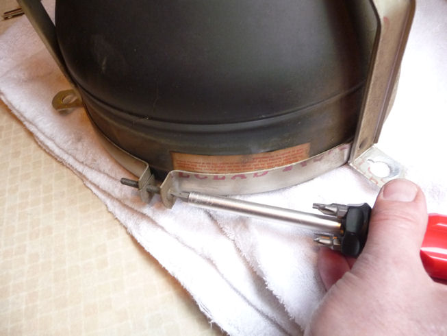
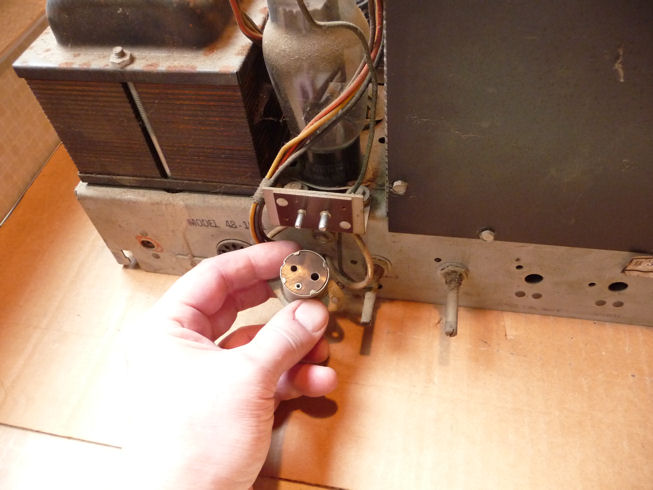
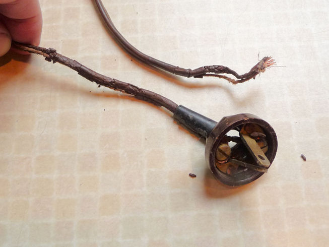
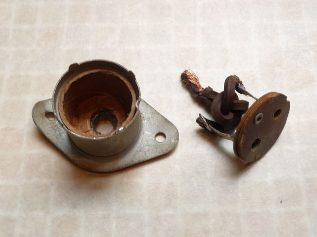
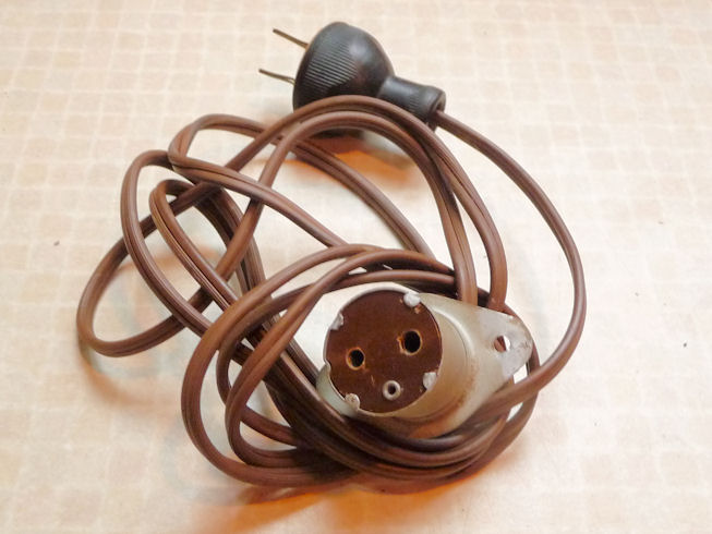
Replacing the Power Cord,
We previously saw that the power cord had been torn off at its root. Like many others,
this television has a safety interlock. The connector shown in this photo is normally riveted
into the back cover, plugging into the chassis when the cover is in place.

The original cord is shot. Bending up four little tabs on the connector
case lets me remove the innards. Soldering on a new cord and reassembling the case takes
only a few minutes.


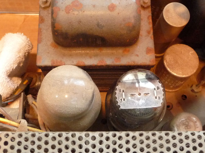
Checking Tubes and Cleaning the Chassis
The first step in every restoration is to clean and test components, starting with
tubes. It makes no functional difference whether a tube's envelope is dirty, but
I need to make sure that all of its pins and their socket holes are free of
dirt and corrosion. Any defective tubes will be replaced, of course.
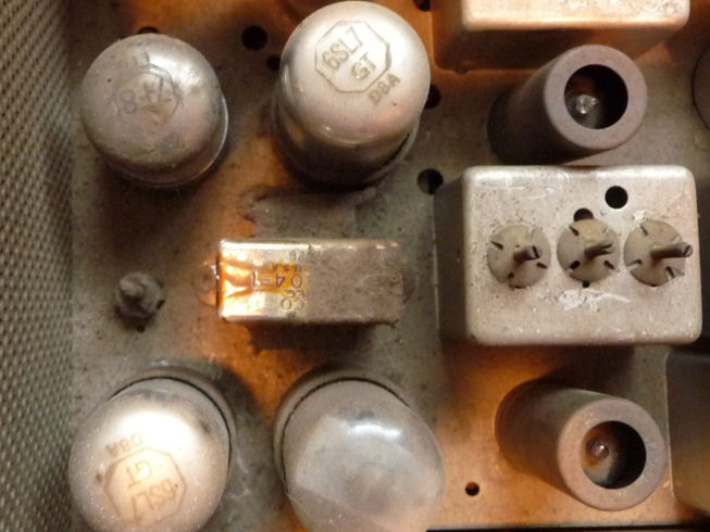
Wow, what a dirty TV. To show how grubby it is, I cleaned one of the
two rectifier tubes (can you guess which one?) and the left side of a little transformer.

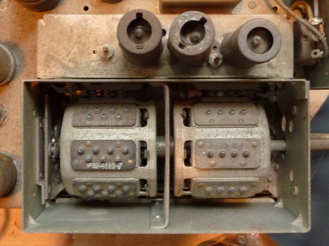
The turret-style tuner definitely needs attention. The top of the tuner cage is missing and the
mechanism is filthy. The tuner is immovable, a common condition when old lubricant
dries and stiffens. Looking back at previous photo, notice how much cleaner the
underside of the tuner is.

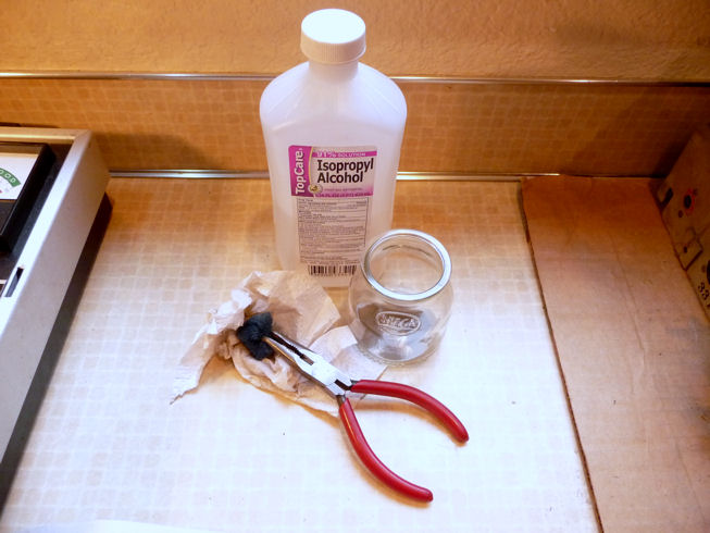
The grime can be removed with isopropyl
alcohol and paper towels. For tight spaces, I use a piece of 3M no-scratch
scrubbing pad held in a plier. In the second photo, I have removed the
high voltage cage and started cleaning the left area of the chassis.

I usually go around the chassis and take one tube at a time,
removing the tube and cleaning its pins and then cleaning around its socket
before putting it back in. As frequently happens, all but two of the
tubes tested OK, and I happened to have spares on hand. By the time
I finished, the chassis was clean and had all good tubes.
Stay tuned . . . .
The next step will be to clean all of the control
potentiometers with DeOxit and follow that up with an electronic lubricant.
After that, if no show-stoppers have appeared, I can apply power for the first
time.
That's as far as I've gotten at this writing in May, 2010. I'll update
this article as I make more progress.
|