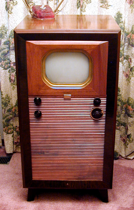
RCA 721TCS Console Television (1947)


This RCA 721TCS was among the earliest postwar TVs. After undergoing total
restoration, this rarely-seen television reigns as one of my favorites.
Description
RCA introduced its model 721 in 1947, the second year of postwar TV production.
This set derived closely from the famous model 621TS from 1946.
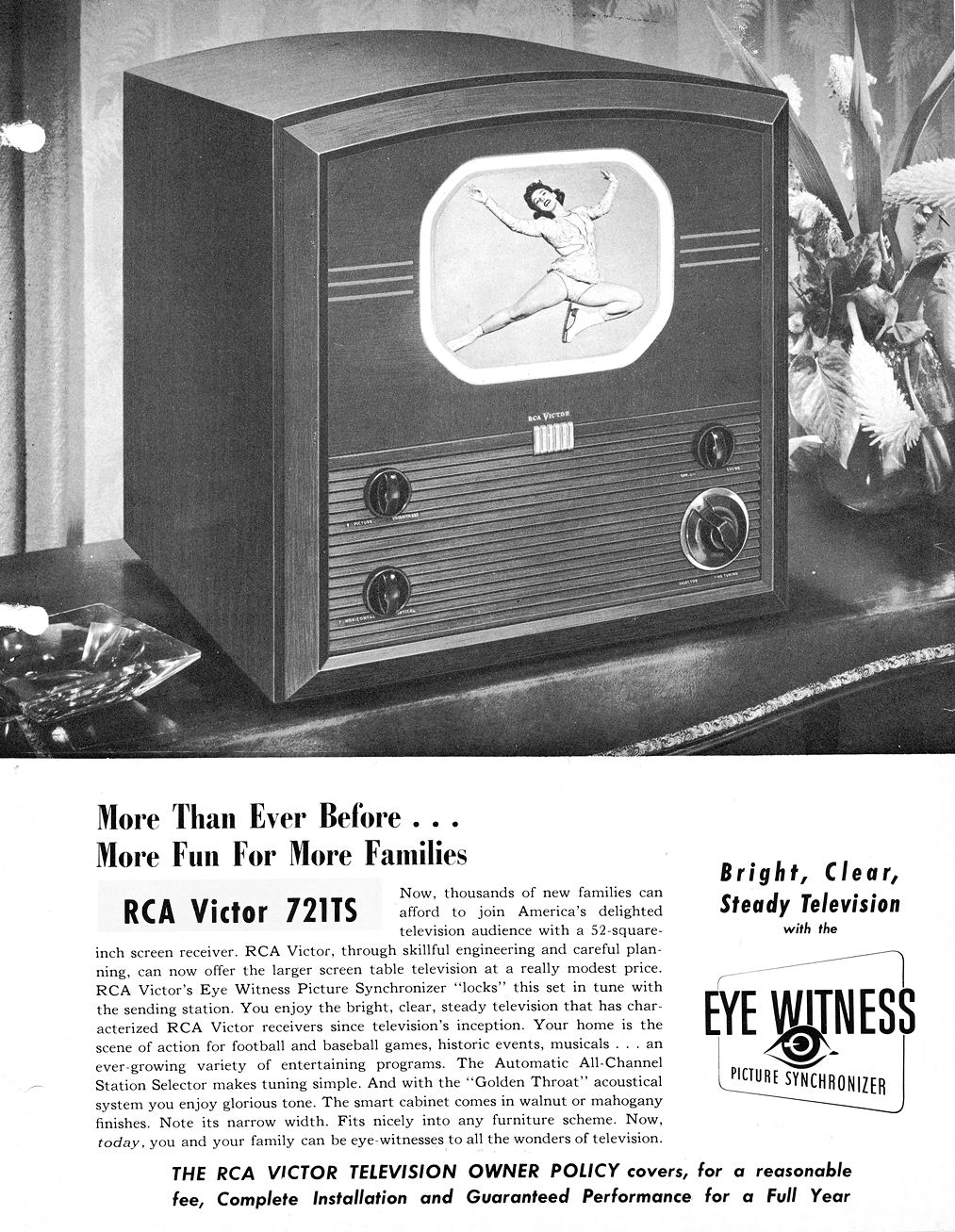
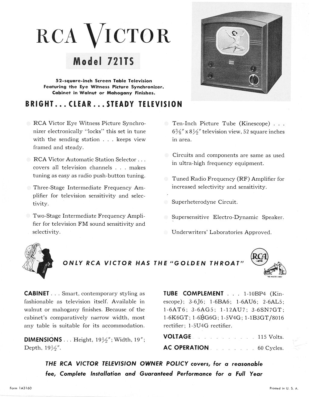
Here are four pages from RCA dealer brochures that describe
the 721TS and 621TS in some detail (thanks to Jim Menning for providing these):
The 621 and 721 are electronically almost identical except for
screen size. The 621's 7-inch screen was replaced by a larger
10-inch picture tube, making the 721 one of the "big screen"
direct-view TVs of its day. (Projection TVs made a bigger image by
projecting onto a screen, of course.)
RCA offered the 721 chassis (KCS 26-1) in two cabinets: the 721TCS console
and the 721TS tabletop. Consoles like mine are much scarcer than the tabletops.
The two flavors of 721 have very few differences apart from cabinet size.
My console has a pilot lamp in front, right below the
grille. It also has a 12-inch cabinet-mounted speaker, whereas the tabletop
has an oval 6 x 4-inch speaker mounted on the chassis. The generous speaker
produces excellent audio, rivaling that of my
DuMont RA-103.
Here is the 721 service manual from Rider's Television Volume One.
To download it to your computer, right-click on the icon below
and choose Save Target As...
The 721 has 21 tubes including the 10BP4 picture tube:
| Tube |
Type |
Function |
| V1 |
6J6 |
RF amplifier |
| V2 |
6J6 |
RF oscillator |
| V3 |
6J6 |
Converter |
| V4 |
6BA6 |
1st sound IF amplifier |
| V5 |
6AU6 |
2nd sound IF amplifier |
| V6 |
6AL5 |
Sound discriminator |
| V7 |
6AT6 |
1st audio amp./bias clamp |
| V8 |
6K6GT |
Audio output |
| V9 |
6AG5 |
1st video IF amplifier |
| V10 |
6GA5 |
2nd video IF amplifier |
| V11 |
6AG5 |
3rd video IF amplifier |
| V12 |
6AL5 |
Video 2nd det./sync. limiter |
| V13 |
12AU7 |
1st & 2nd video amplifier |
| V14 |
6SN7GT |
Sync. amp./sync. separator |
| V15 |
6SN7GT |
Vert. osc./discharge/output |
| V16 |
6SN7GT |
Horiz. oscillator/horiz. control |
| V17 |
6BG6G |
Horizontal output |
| V18 |
5V4G |
Damper |
| V19 |
1B3GT |
High voltage rectifier |
| V20 |
5U4G |
Low voltage rectifier |
| V21 |
10BP4 |
Kinescope |
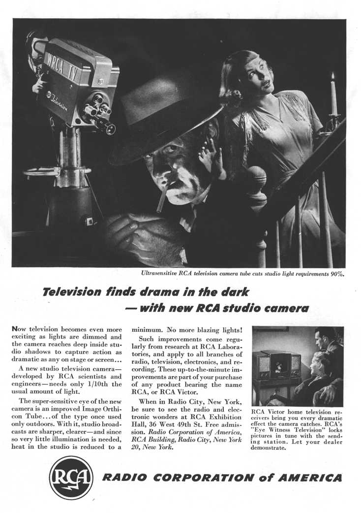
If you're looking for 721 magazine ads, you can quit searching right now.
In the immediate postwar years, RCA ran what I call technology ads,
touting their picture tubes, TV cameras, and so on. When consumer sets
appeared in these ads, it was only in a little corner inset, without
any model number or pricing. For instance, this ad shows a model
630TS in an inset:
In case you're curious about RCA model numbers, in 1946-1947 the first digit
indicated the year and the next two the number of tubes. TS meant television
set and TCS meant television console set. Thus, model 621TS was a 21-tube
tabletop made in 1946. 630TS was a 30-tube 1946 tabletop, and 721TCS was a 21-tube
console from 1947. In later years, RCA introduced other model numbering schemes.
Finding the RCA 721TCS
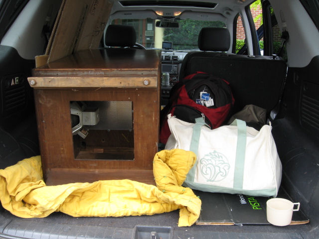
I purchased this TV in August, 2011. My wife and I drove to pick it up in Forest
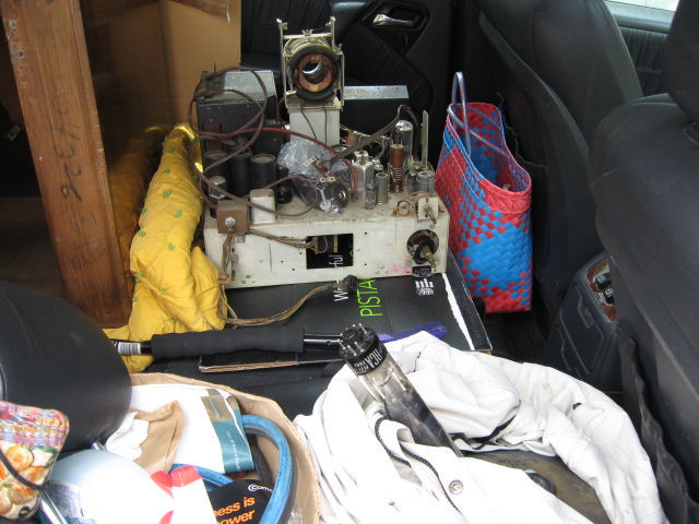
Grove, Oregon, a 500-mile round trip. These photos show the set in our SUV after I
removed the chassis and picture tube and stowed
everything for the drive back to Washington.


As with other RCA TVs of this vintage, such as my
630TS, it's critically important to
remove the picture tube for transport. The CRT's heavy front bell is
supported only by small clips in the front of the cabinet, not by the
chassis. (Before removing the chassis from behind, remove the
front panel and pull the picture tube from the front.)
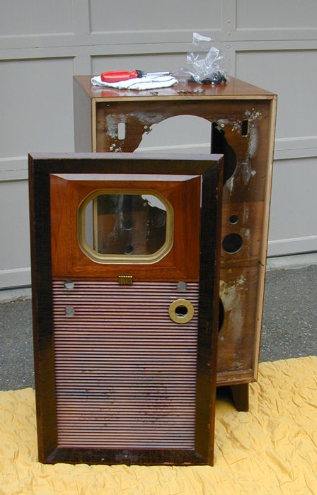
The next photo shows the cabinet after unloading at home:
I'd call this a Machine Age design, clean and stylishly understated.
The cabinet has a walnut finish, with veneer
on the top and sides. The removable front panel is built from several pieces of solid
walnut, beautifully milled.
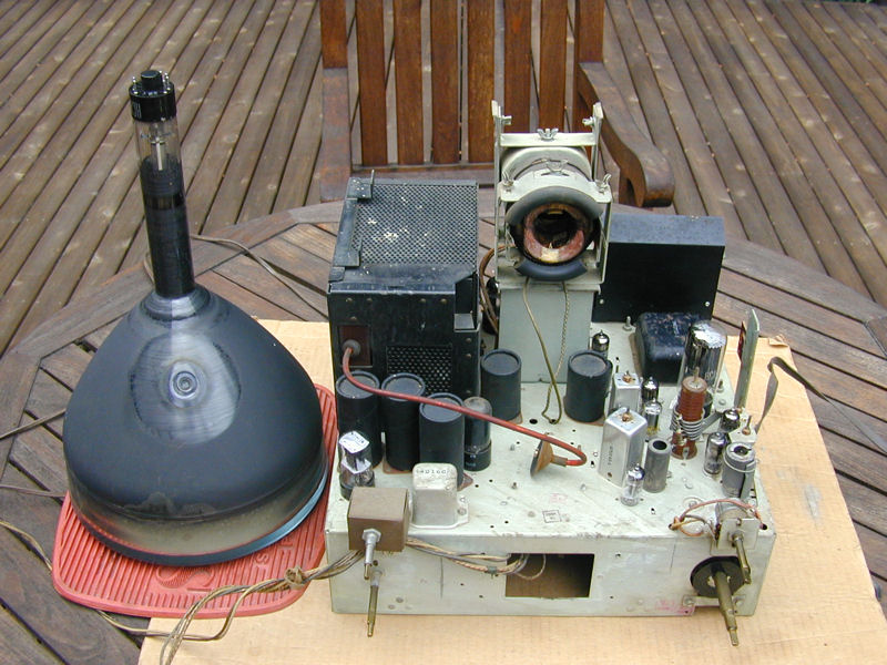
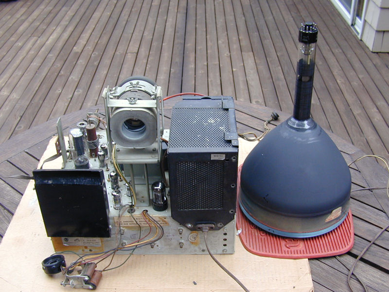
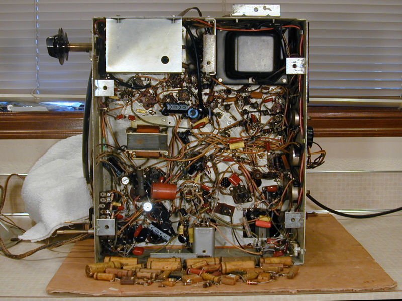
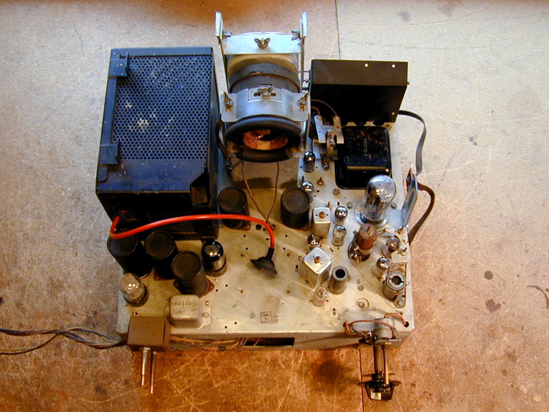
Here is the chassis as found. This TV was clean and obviously well cared for.

Seen from the rear, you can notice the family resemblance to my 630TS, with high-voltage
cage at the right and a flat compartment for power resistors on the left.
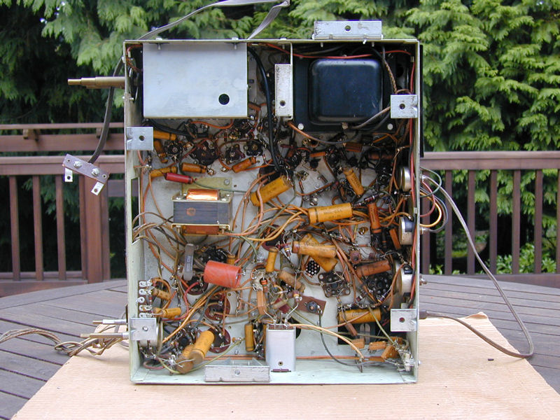
The layout underneath is uncluttered. Recapping
this television should be an easy task. In this view, the tuner is at
upper left and the stout power transformer at upper right.
Electronic Restoration
After cleaning the chassis, I tested the tubes and cleaned all of their pins,
as well as the tuner and all controls. The picture tube looked strong
on my Sencore CR70 tester, a welcome sign.

Recapping did not produce any surprises. As often happens, the TV
woke up in stages as I replaced more and more
capacitors.
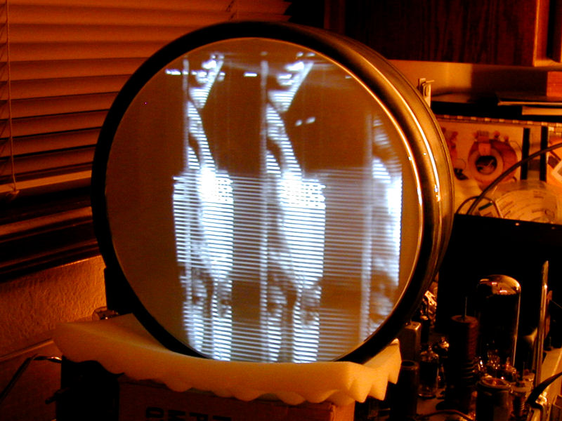
After replacing the electrolytics, I got faint audio
and a dim raster with severe sweep problems and little hint of the video signal.
Click the following icon to view an animated .GIF picture that gives you
an idea what I saw:

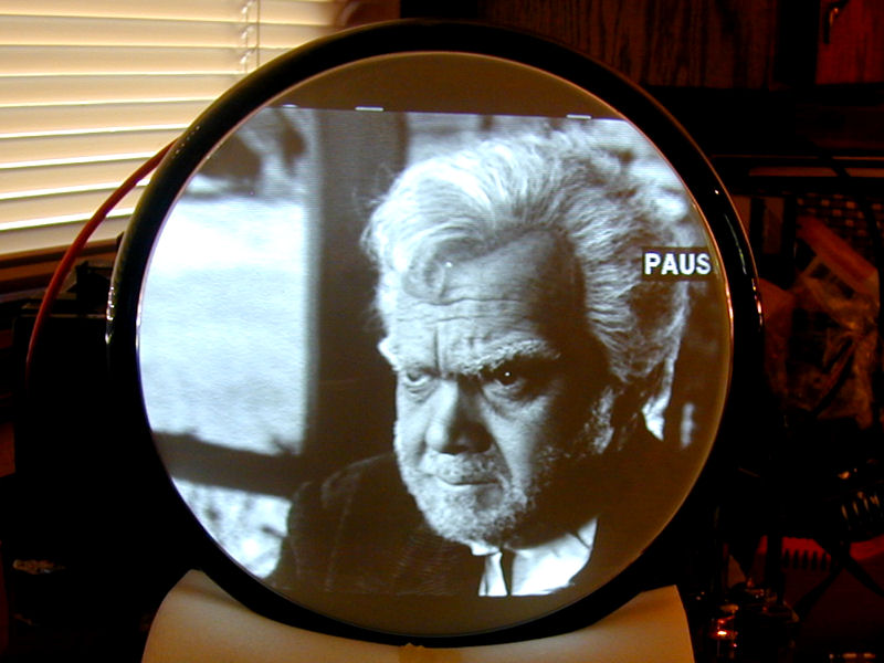
After further replacements, the audio was outstanding and the picture
had greatly improved, with better brightness and contrast, although the vertical
and horizontal sweep remained imperfect:
Here's a look at the chassis after most of the
work was done. In front is a pile of capacitors and resistors replaced up to
that stage.

Not shown in the discard pile are the old electrolytic capacitors. Rather
than restuff the old cans, I installed new caps underneath and left the
originals above the chassis for appearance. For more
on the pros and cons of restuffing, with illustrated descriptions of various
techniques, see my recapping
article.
While I was engaged in recapping, a fellow 721TCS owner reported trouble
with mica capacitors in the horizontal circuits (you can read the full
discussion
in the antiqueradios.com TV forum). I decided to replace all of
those micas to head off trouble.
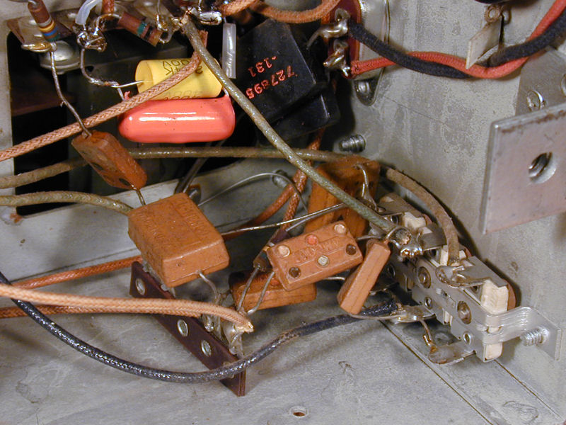
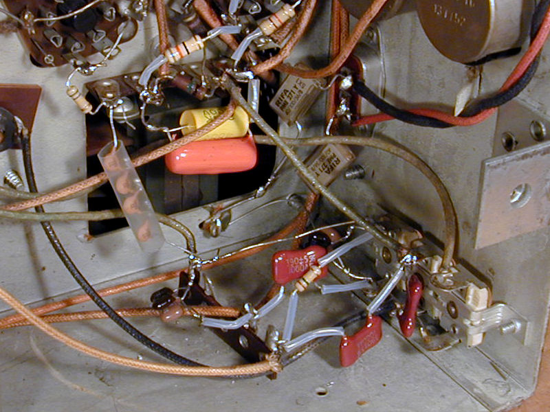
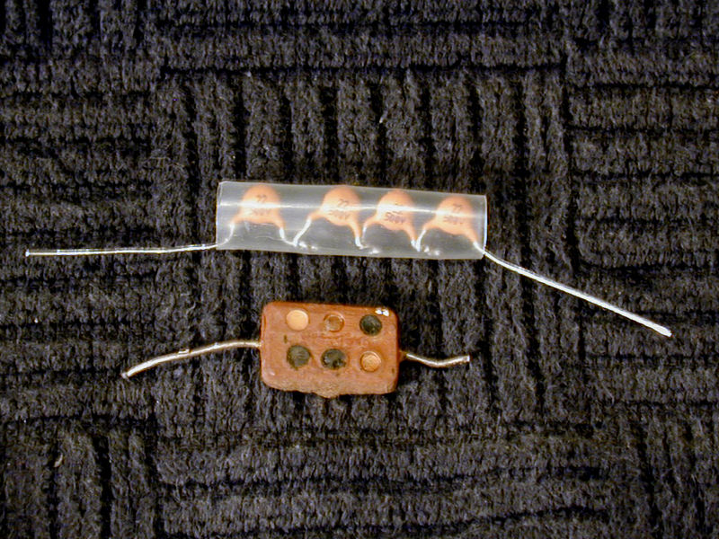
The next photos show a cluster of six mica caps on the horizontal drive, frequency,
and locking adjusters, before and after replacement:


One of the caps in that group had a value not easily
found: 5pf, rated for 1.5 kilovolts. You could make a substitute
by connecting two 10pf/1KV caps in series, which doubles the voltage
rating and halves the capacitance, but I had no such caps on hand.
The next photo shows the best that I could do using available parts.
Inside the insulating sleeve are four 22pf caps, each rated for 500
volts. The result is one 5.5pf cap rated for 2KV.

This replacement looks a little kludgy, and you normally want to stay
very close to the rated capacitance when changing caps in horizontal circuits.
I hoped that this cap would work well enough to let me continue restoring
the TV, anyhow, while searching for an exact replacement.
After finishing off those mica caps, I replaced some marginal resistors in
the vertical circuits and tried the television again. The results did not
disappoint:
Here is the restored chassis. I like the compact size of this set. It's
considerably smaller than my 630TS, yet it performs very well.

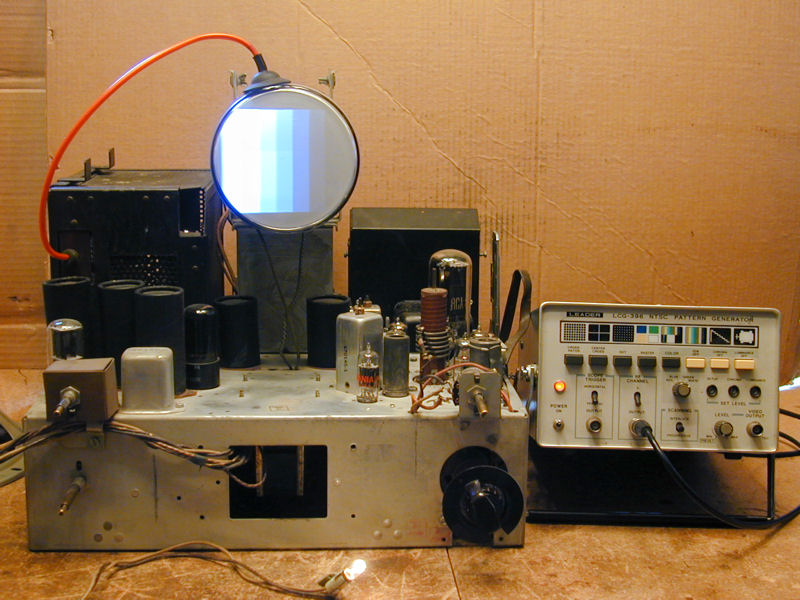
Time for some final adjustments, including an alignment of the audio
section. In this photo, I have begun setting up by
temporarily installing my 5AXP4 picture tube in place of the unwieldy 10BP4.
The little substitute CRT is much easier to manage on the workbench. After
the chassis is back in the cabinet, I'll make the final adjustments
for width and height.
Following a few more tweaks, the 721TCS performed as well as
any of my 1940s TVs, with an extraordinarily bright picture.
Cabinet Restoration and Final Assembly
When purchased, the cabinet was in average shape, with assorted nicks
and scuffs, plus a few little veneer chips around the edges. The bezel
around the front panel had other problems; the finish had been
scraped off in a few spots and its whole surface had a network of
"alligator" surface cracks.
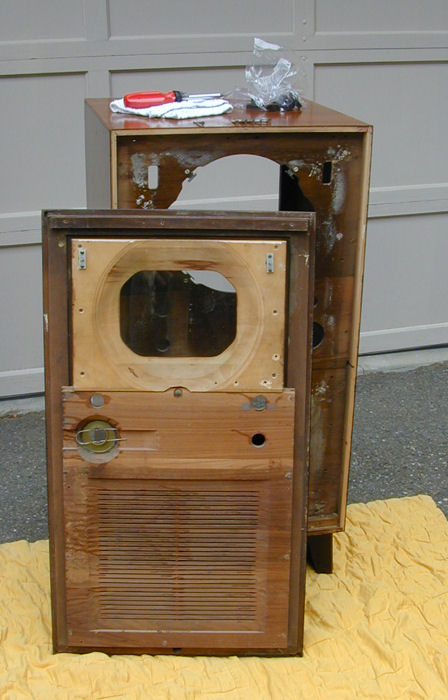
Before sending it off for refinishing, I took the cabinet apart.
You need to remove the front panel to do electronic restoration,
anyway, since the picture tube is drawn out through the cabinet front,
just as with my
RCA 630TS and
Philco 49-1240.
The entire cabinet front can be removed as one piece. Notice how the
rear of the CRT mask is recessed to fit the bulbous face of the
picture tube.
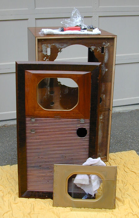
The safety glass is held between two pieces of wood: the gold painted mask and
the finished walnut front bezel. In the next photo, the gold mask and glass
are sitting on the ground.
The cabinet was restored by Michael Mueller, who also restored my
RCA CT-100,
DuMont RA-103,
and RCA CTC-11 cabinets.
I brought the refinished cabinet home in pieces and temporarily
reassembled it for a coming-home photo.
In the next shot, I have installed the chassis and brought in the
CRT. It will slide in from the front, of course.
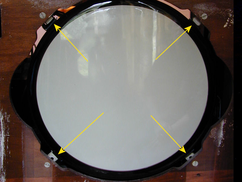
It's vital to adjust the CRT supports to hold the picture tube snugly
in place. This photo illustrates the four supports:

Each support can be slid in or out by loosening its screw. To
ensure that the tube neck is straight within the yoke, the edges of
the CRT should be an equal distance from the cabinet opening on
the sides, top and bottom. You also want the supports to exert a bit of
pressure, to keep the tube from rattling or slipping if you
move the television.
After sliding in the picture tube, press it back
as far as possible, so that the rear of the bell rests against
the front of the rubber yoke cushion. If your CRT supports are
adjusted correctly, they'll hold the tube securely in place long enough
for you to put on the front panel.
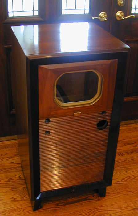
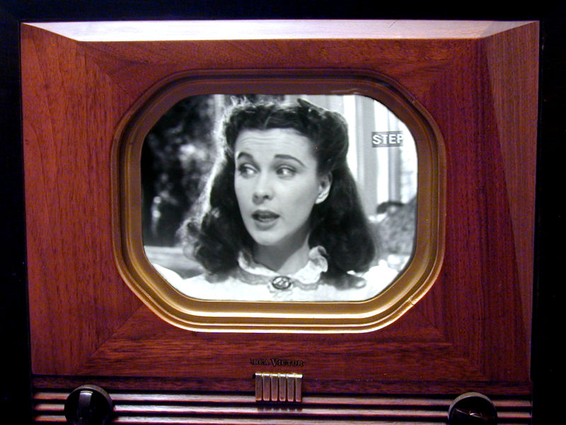
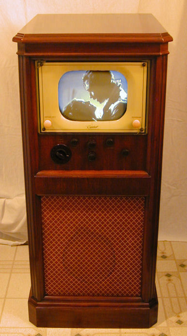
After I reinstalled the front, I made final adjustments for height, width, and centering, and declared the project done at last. Here's the finished set.
The picture is outstanding and the audio quality is all that I had hoped.
With a very strong CRT, this is the brightest 10-inch television in the
house.
Final Thoughts
The 721TCS is not particularly difficult to restore and it's
an excellent performer. As I accumulate more TVs, I need to become
much more selective, but this one is definitely a keeper. It's historically
important as well as a pleasure to watch.
This RCA will make a nice companion to my
Capehart-Farnsworth 661-P,
another 10-inch TV-only console with a tall, narrow cabinet:
One of these days, I should take a photo of the two side by side.
|