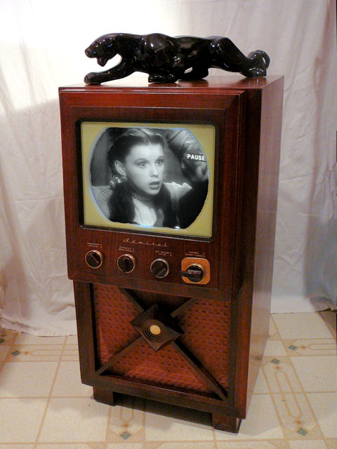
Admiral Model 24C15 Television (1948)


This Admiral model 24C15 TV from 1948 has a 12-inch picture tube.
Petite for a console television, it's only 34 inches high and 18 inches wide.
Description
Admiral TVs of the 1940s were well designed and popular. Although the
company did not have the marketing clout of juggernaut RCA or the
best-in-show glamour of DuMont, Admiral sets sold well and
servicemen knew them as sturdy performers. Next to RCA, Philco, and Motorola,
Admirals are among the most common 1940s sets to be found today. If you pay more than
about $100 for one, you're not looking very hard.
Admiral used this basic chassis, with changes, in dozens of early models,
with picture tubes measuring 10, 12, or 16 inches, and including tabletops and
TV/radio/phono combinations as well as this TV-only console. The first
page of the Riders manual has a chart listing more than 50 model numbers!
The Rider's service
manual is available from the Early Television Foundation schematic
archive.
Click on the following thumbnail to view the 24-megabyte manual in PDF format;
to save it, right-click on the thumbnail and choose Save Target As.
The model number of my set is 24C15 and the chassis is type 20B1,
using 25 tubes in two chassis. The main chassis has 21 tubes:
| Tube |
Type |
Function |
| V101 |
6AG5 |
RF Amplifier |
| V102 |
6J6 |
Ratio Detector |
| V201 |
6AU6 |
1st Audio IF Amplifier |
| V202 |
6AU6 |
2nd Audio IF Amplifier |
| V203 |
6AL5 |
Ratio Detector |
| V301 |
6AU6 |
1st Video IF Amplifier |
| V302 |
6AU6 |
2nd Video IF Amplifier |
| V303 |
6AU6 |
3rd Video IF Amplifier |
| V304 |
6AL5 |
Video Detector |
| V305 |
6AU6 |
Automatic Gain Control |
| V306 |
6AC7 |
Video Amplifier |
| V307 |
12LP4 |
Picture Tube |
| V401 |
6SN7GT |
Vert. Oscillator / Sync Inverter |
| V402 |
6K6GT |
Vertical Output |
| V403 |
12AU7 |
Sync Separator / Clipper |
| V404 |
6AL5 |
Horiz. Sync Discriminator |
| V405 |
6SN7GT |
Horizontal Oscillator |
| V406 |
6BG6G |
Horizontal Output |
| V407 |
1B3GT |
High Voltage Rectifier |
| V408 |
6W4GT |
Damper |
| V409 |
1B3GT |
High Voltage Rectifier |
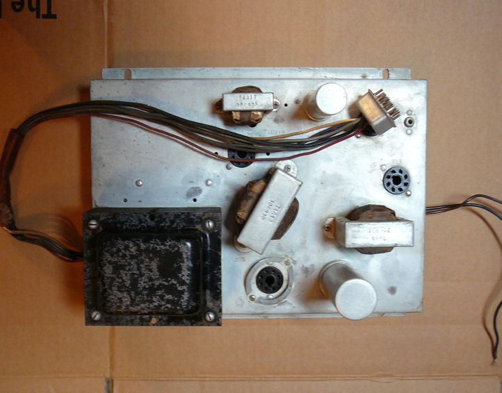
The four-tube power/audio amplifier chassis is mounted in the base of the cabinet:
| Tube |
Type |
Function |
| V501 |
6SQ7 |
Audio Amplifier |
| V502 |
6V6GT |
Audio Output |
| V503 |
6X5GT |
Low Voltage Rectifier |
| V504 |
5U4G |
High Voltage Rectifier |
The electronic design is pretty conventional, with split-sound audio and
automatic gain control (AGC). The combo Admirals (those with radio and phono)
have a deluxe audio section with a push-pull output stage.
This model 24C15 has a 12-inch 12LP4 picture tube, giving it the same size screen
as my DuMont RA-103 and
Philco 49-1240.
Finding an Admiral Console
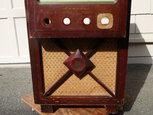
I spotted this set in the local craigslist ad, which said, "First TV
on the block — $10!" The seller was the second owner and it had
been her bedroom set before it was replaced with a bigger television.
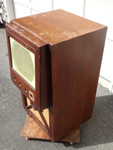
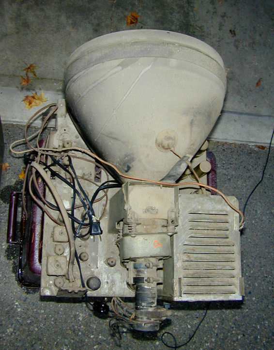
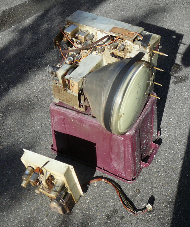
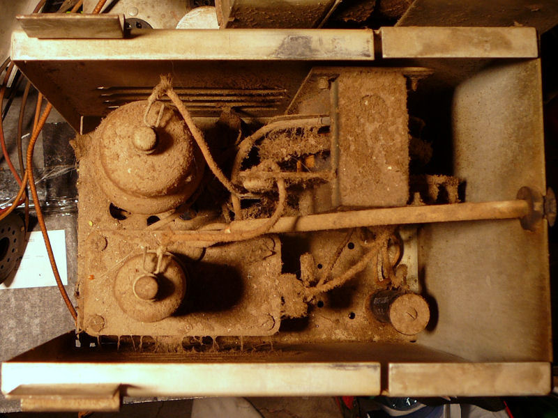
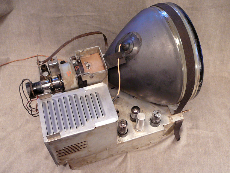
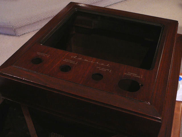
Here is the TV as I found it, complete (except for a back cover) and very dirty.
The top of the cabinet protrudes over the bottom, giving it
a slightly top-heavy look. My cabinet has many scuffs and scrapes,
but no major damage.
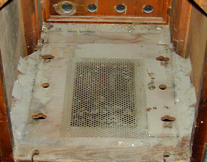
A bird got into the cabinet at some point, leaving droppings on the tube.
Further evidence of the crime could be seen on the front of the chassis shelf.


This non-greasy sort of dirt looks daunting but it's easy to clean. It's harder
to clean sets that are coated with decades of cooking goo and tobacco tar.
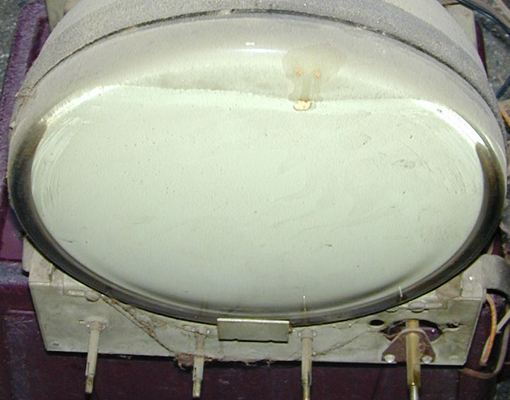
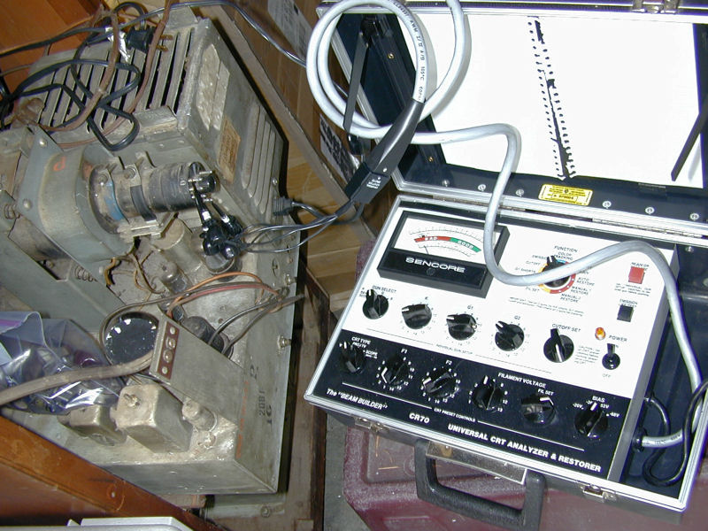
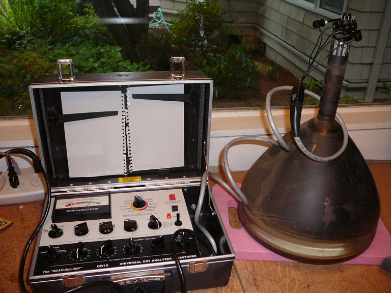
More problematic were the results from my Sencore CR70 picture tube tester.
This tube looked like a dead duck, even after "cooking" overnight on
the tester with slightly elevated filament voltage, a process that
frequently wakes up long-unused CRTs.

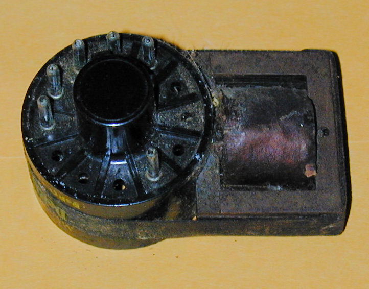
To be honest, I hadn't expected much from this tube. When I
had removed the chassis, I found this brightener plugged onto
the CRT base at the back.

A brightener slightly steps up the filament voltage, boosting the brightness
on a worn-out picture tube. (You can read more about brighteners in my
DuMont RA-113 article.)
This tube may be on its last legs, but I'll reserve judgment until the TV works well
enough to light up a CRT.
Cleanup
Let's get these chassis cleaned up! I began by blowing off dust with a shop-vac.
Then I turned both chassis on their sides and cleaned them using a spray bottle of isopropyl alcohol
and a soft brush, working from top to bottom.

Alcohol evaporates quickly without residue. Working outdoors in the warm
sunlight, there is no risk of soaking coils or other parts that don't like moisture.
Bringing them indoors, I did another round of cleaning with alcohol, rags, and
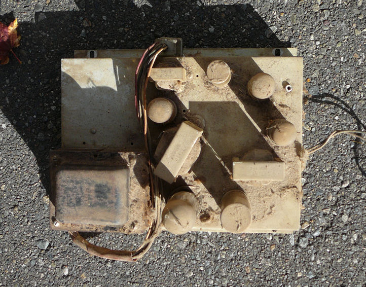
paper towels. Naval Jelly took care of some light surface rust. Here are before and
after photos of the small power/audio chassis.

The power transformer looked scabby after rust removal, so I applied
black Rustoleum paint to freshen it up and prevent future rusting.


When I opened the high-voltage cage, I wished that I had started cleaning it outdoors.
Yuck!

After removing the worst filth, I lifted the little
platform that holds the 1B3GT HV rectifier tube. It's prudent to clean
under the socket to reduce the risk of arcing.

Before putting the platform back in place, I'll test the resistors
on the socket. Failure here may blitz your high voltage, causing
a quick fade to black.
Cabinet Restoration, Phase One
I usually restore a set's electronics and then worry about the
cabinet. I enjoy the electronic work more than the refinishing, and I have
found that getting a TV to work well inspires me to complete the cabinet.
In this case, I tackled the cabinet first. It was mid-September,
and in the humid Pacific Northwest, it's preferable to spray lacquer before
the fall rains begin. I'll have all winter to do the electronics.
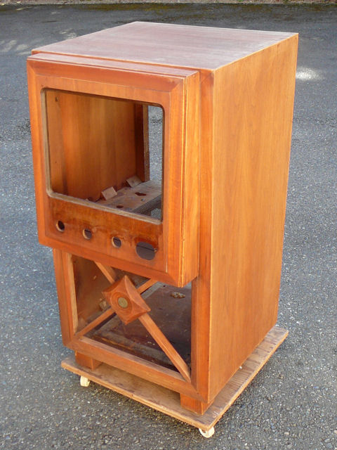
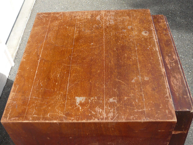
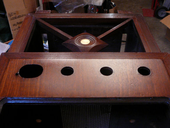
The cabinet was structurally sound but not pretty. The top
had some finish loss and the edges had plenty of scuffs and
shallow gouges.


The top and sides are quite faded from light exposure. We can
tell the original color by inspecting protected areas such as the
edges exposed by removing the speaker grille frame. Those parts look
medium brown, so that's how I'll recolor the cabinet.
The safety cover, screen bezel, and grille frame are
removed with screws from inside.
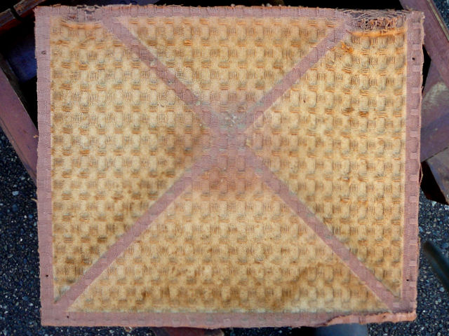
Ugh. The grille cloth is stained, badly faded, and falling apart in one corner.

Notice how UV exposure has lightened the color. The strips covered by the
crossbars and cabinet edges are much darker, a sort of maroonish brown, while
the exposed areas have faded to a wheat color. The fabric looks like woven cotton.
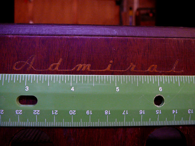
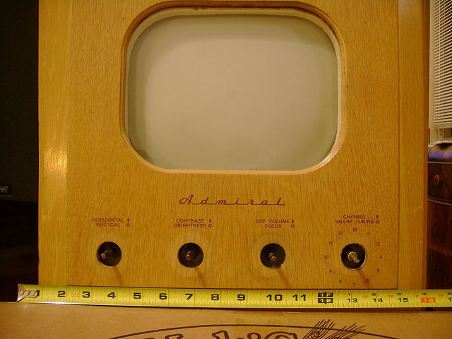
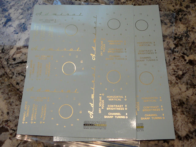
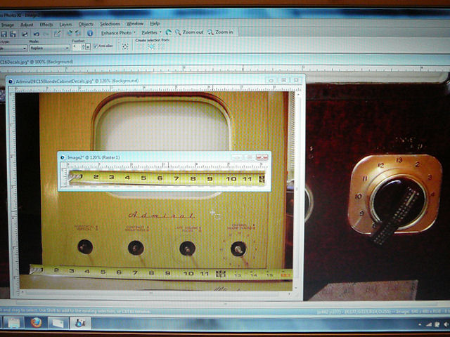
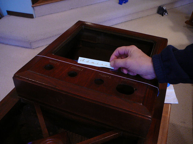
In case the decals can't be preserved, I photographed all of them next
to a ruler to show the exact size. The photos could be sent to a decal maker
to create reproductions, as I did for my
RCA CT-100 color television.

The Admiral logo in the previous photo is intact, but it looks like someone slopped dark
red stain over this part of the cabinet. The decal should be bright gold, not a muddy light
mahogany. The decals near the knobs are also quite worn, so even if I can safely remove the
old stain, they may not look good.
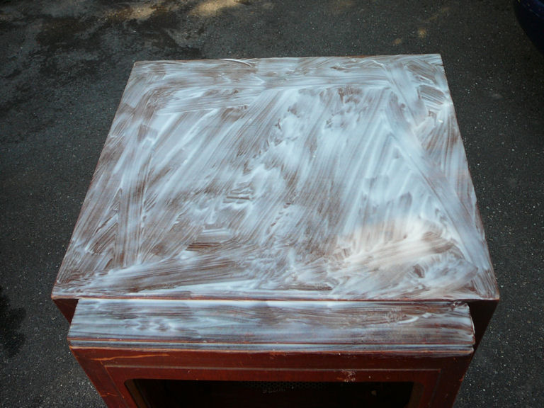
The finish on top is so damaged that stripping is the only option. I began with gel type stripper:

Gel stripper works slowly and makes a mess, since you need to dispose of
lots of scraped-off stripper mixed with old finish. On the positive side,
this stripper doesn't generate toxic fumes.
After I had treated most of the cabinet with gel stripper, I read a note about
removing lacquer with a 50/50 mixture of acetone and lacquer thinner. I tried it
on the complicated front lower portion, and I found it fast, easy, and much
less messy than gel stripper. You simply loosen the finish with a rag dipped in
the mixture and wipe it off with another rag or paper towels.
The hitch is that acetone and lacquer thinner are toxic to breathe, as well as
flammable. They should be used outdoors, or if you must work indoors, with excellent
ventilation, a mask, and rubber gloves.
Hours later, the old finish has been removed. I skipped the area surrounding
the decals in case I want to try preserving them.
I lightly sanded the entire cabinet and then washed it with mineral spirits
to remove the sawdust. This removed a lot of scratches, especially on the top.
The next step was to stain the stripped cabinet. I chose a medium brown color
that approximated what was left of the finish around the decals.
Around this time, I contacted the Antique Radios television forum, asking whether
anyone had created reproduction decals for this console. Nobody had done so, but
with the aid of a couple of generous forum members, we set about having reproductions
made from photos of a console with intact decals. You can read that discussion
here.
After staining, I applied Crystalac grain filler to the cabinet top. I had sanded
the top more than other parts, and the grain filler will give it a smooth
appearance like the rest. After scraping off excess filler and letting it
dry, I wet-sanded the top very lightly.
Next, I sealed the entire cabinet with two coats of shellac, lightly wet-sanding
with mineral spirits and fine paper after each application. This produced a
smooth, even surface ready for lacquer.
Special Treatment for Decals
While performing these other steps, I treated the front panel with the decals somewhat differently,
since I wasn't sure whether new decals would be available.
First, as a learning exercise, I wanted to see whether the old decals could be preserved,
with the original finish "reflowed" around them to smooth out the many chips
and scrapes in that area.
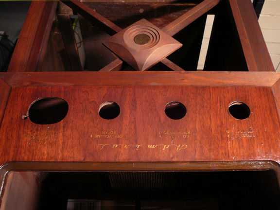
I began by removing most of the old lacquer around the decals. Then I tinted some lacquer and brushed
it thickly onto the newly-bared surrounding areas. This would provide some extra finish to replace
what I had removed. After that layer dried, I reflowed the entire panel,
including the decals, with a mixture of brushing lacquer, thinner, retarder, and a little color.
The result can been in the next photo:

If the decals had been less worn, I might have stopped there and declared victory.
The decals were brighter gold than before, and the surrounding finish looked smooth
and consistent. However, parts of the decals had been worn off completely. No
amount of finish smoothing could replace the missing bits. What's more, mixed in with the
old finish were blobs of "stuff" that wouldn't dissolve, perhaps
left over from when someone stained the front.
By this time, it looked like new decals would become available, so I abandoned the
reflowing experiment and prepped the front panel to match the rest of the cabinet.
First, using my solvent mixture and a cotton swab, I loosened the finish over
the decals and then gently scraped off the decals.

Next, I covered that stripped area with tinted brushing lacquer, let it dry,
and then reflowed the entire panel to approximate the overall cabinet
color.

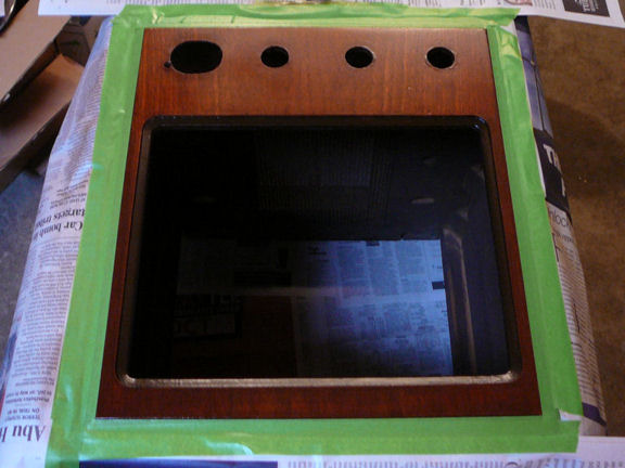
At this stage, I was nearly back where I had begun with that panel, minus the
decals. The reflowed finish was thinner than what I had built up on the
rest of the cabinet, so I masked it and sprayed on more clear lacquer,
lightly wet-sanding between coats.


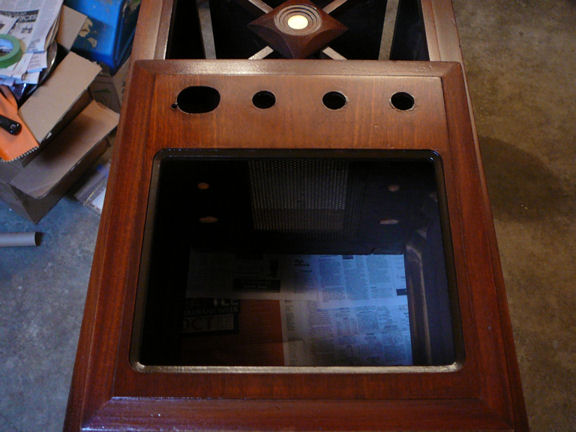
Next, I gave the entire cabinet a couple more coats of clear lacquer,
wet-sanding after the first to achieve a flat, smooth finish. Still
waiting on the decals, I set the cabinet aside to work on the chassis.
Electronic Restoration
Before replacing any components, I began by testing all of the tubes and cleaning
their pins and sockets. I also cleaned the tuner and all controls (volume,
contrast, etc.).
These basic tasks are essential to every restoration, so I have detailed them in an article,
First Steps in Restoration.
Initial Cleaning and Testing
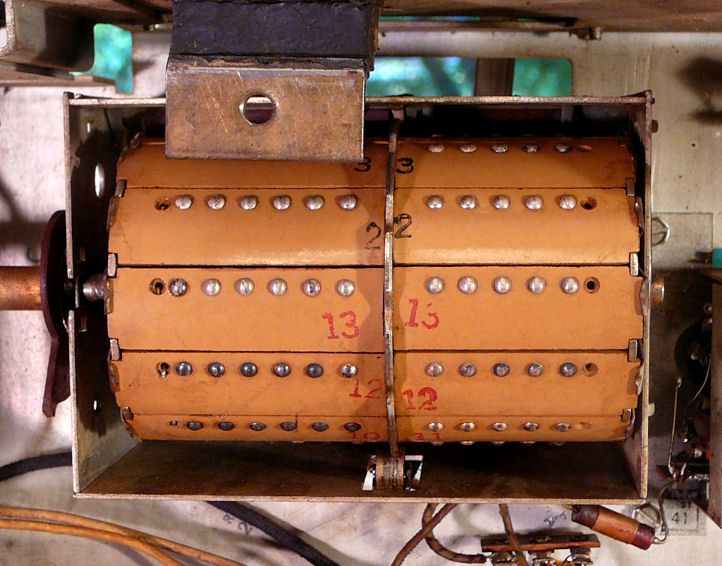
This Admiral uses a turret style tuner that's easy to clean. In the next
photo, I have cleaned the contacts for channels 3, 2, and 13. You can see
the dark corrosion on the contacts for channels 12 and 11.

Never use abrasives on contacts like this. I cleaned these
with a soft cloth dipped in isopropyl alcohol.
I found two or three weak tubes among the originals and replaced them with
fresh ones from my stash. The picture tube still showed near zero emission,
so I used the "auto restore" function on my Sencore CR70 in an
attempt to bring it back to life. Now, the emission tested well into the
Good zone.

This CRT won't last forever, but it is vastly improved.
The graphite "aquadag" coating has flaked off in many spots.
(The coating forms part of a filter capacitor for the high voltage circuit.) I'll cure that
by spraying on a couple of coats of Aerodag G.
.
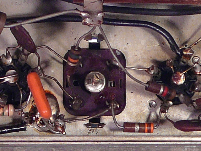
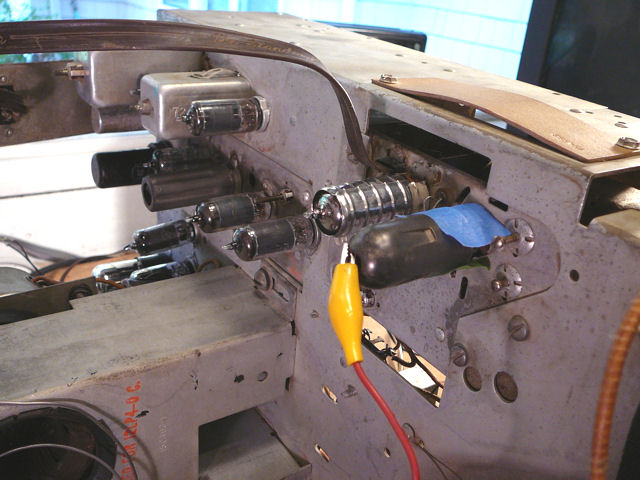
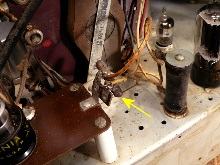
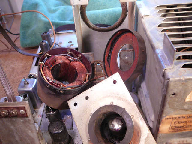
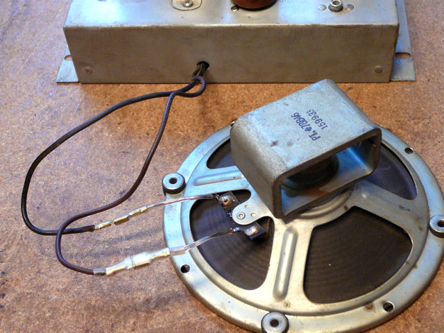
Speaking of aquadag, look at this funky wire loop that someone screwed onto the chassis.

The loop goes around the neck of the CRT when that's installed and it seems
intended to make a ground connection to the aquadag coating.
That connection is normally made by a spring loop bolted to the chassis below
the picture tube. I'm guessing that the aquadag in the area of the factory connector had
been scraped away, so the repairman improvised a new connection with this little
lasso of solder rather than recoat the picture tube.
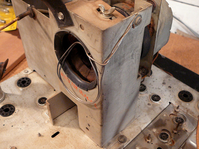
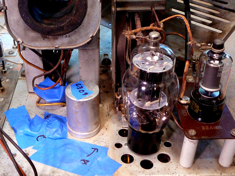
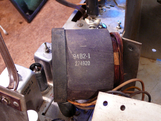
Notice the orange stamp on the yoke support indicating that this TV uses
a 12LP4 picture tube. This chassis was made in various flavors
and the factory provided "sticky notes" like this and even colored dots to
help the serviceman keep it all straight.
Restoring the Power/Audio Chassis
I'm ready to start
replacing capacitors, and as always, I'll
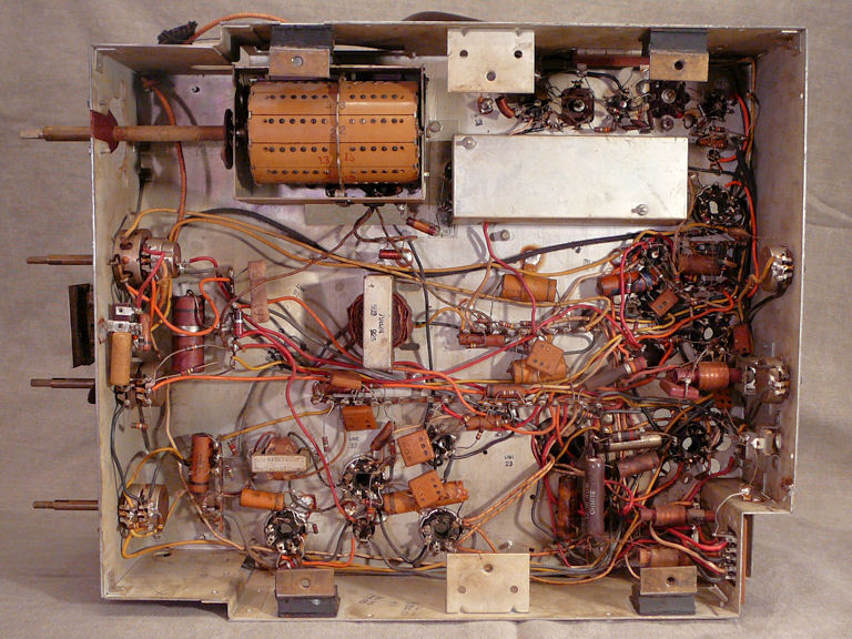
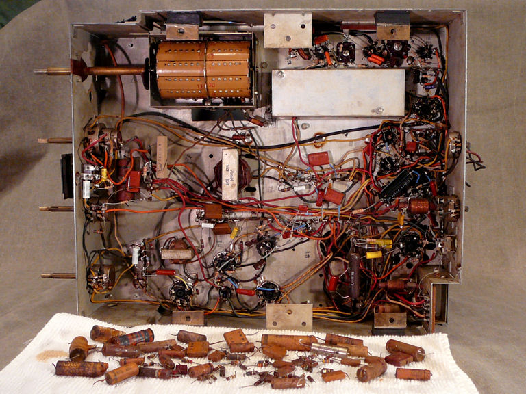
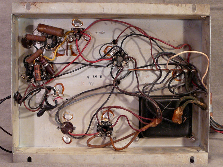
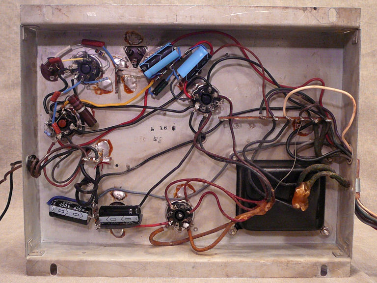
begin with the power supply. Here's a look under
the power/audio chassis, which is roomy and easy to work on.

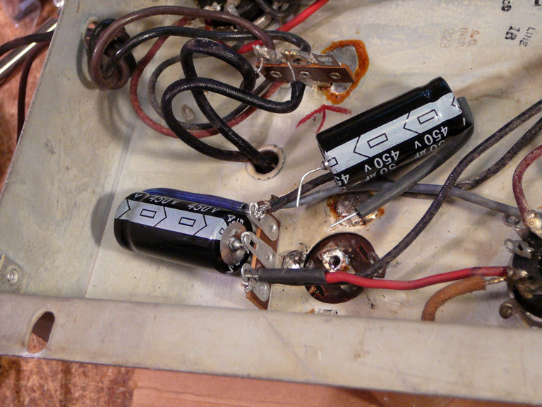
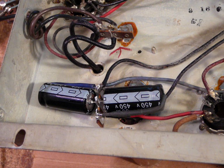
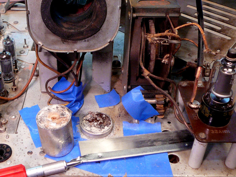
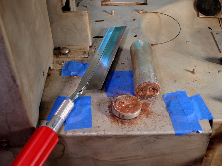
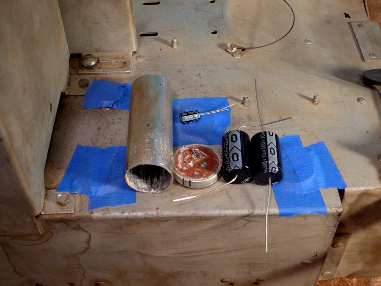
With so much open space underneath, there's no need to restuff the old
electrolytic cans. I'll disconnect them and leave the cans untouched for
appearance's sake. These photos show how I mounted two new electrolytics
on a new terminal strip to replace two electrolytics in the C506 can.


The rest of this job was straightforward.
In addition to capacitors, I replaced some resistors that had
drifted beyond tolerance.

Recapping the Main Chassis
The main chassis will require more work, but it's also comparatively
uncluttered.
One of the electrolytic cans, named C309 in the Riders manual, sits
over a congested chassis area and its can is short and squat. I'll stuff two of its three capacitors
in the hollowed shell and wire the third underneath.


All three of the C407 electrolytics will fit easily in its tall can.


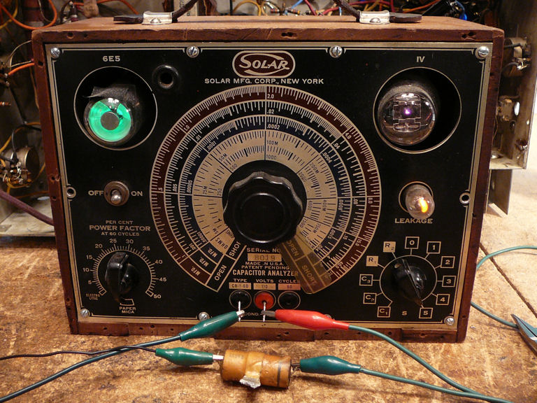
The rest of the recapping was routine, and in case you're wondering why I
don't test old paper and electrolytic caps before replacing them, here's one that I threw onto
the tester just to prove a point. To the right, above the Leakage sign,
the light glows a bright orange, signaling that this capacitor is junk.

Before long, all of the electrolytics and paper caps had been replaced.
First Image
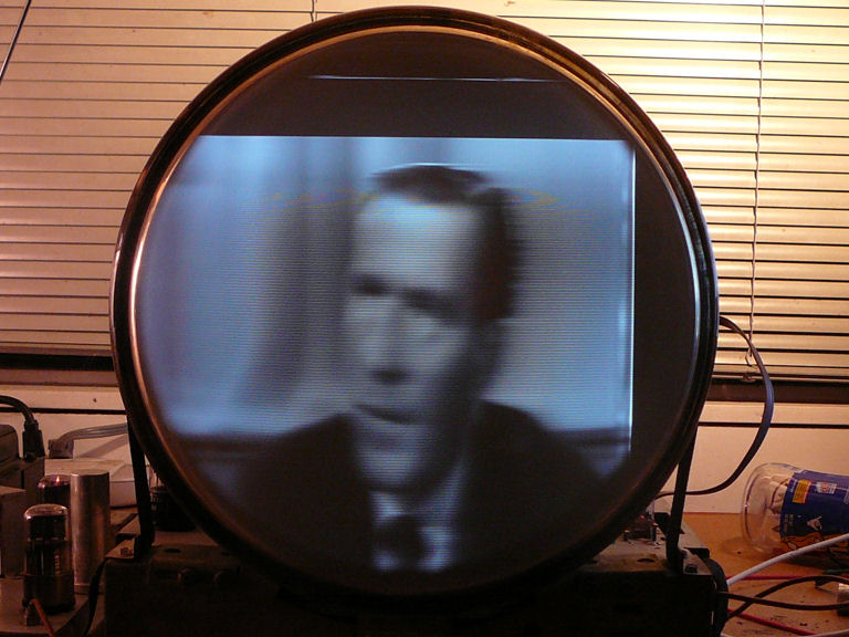
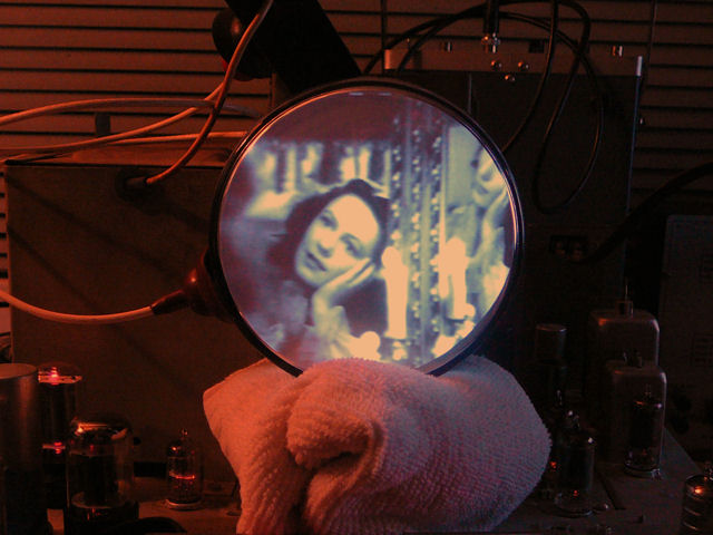
I'm eager to try out this TV. Using my metered variac,
I gradually brought up the power and the result was encouraging.
A coherent image demonstrates that many of the TV's sections—power
supply, tuner, video IF and output, vertical and horizontal sweep, and high voltage—are operational.
In the not-so-great category, the audio is completely silent and there's something
funky with the horizontal. Notice the bright foldover line on the right border
and the comb-like tearing on the right edge of the man's head.
The focus is obviously poor, as well. Still, this is not too bad for an
initial power-up.
Replacing the Aquadag CRT Coating
Now that I knew my rejuvenated picture tube was usable, it was worth taking the time
to replace the damaged aquadag coating and glue the loose tube base.
We previously saw how a shade-tree TV mechanic had worked around the bad
aquadag by putting a loop of solder around the picture tube neck.
He had also "fixed" the loose picture tube base by winding it
with several loops of electrical tape. That kept the base from falling
off completely, but I could still feel it flex whenever I plugged in
the CRT.
I removed the tape from the base and cleaned off the adhesive residue, and
then secured it with sensor-safe RTV, squeezing the adhesive into the
gap between the base and the tube neck. I taped the base securely
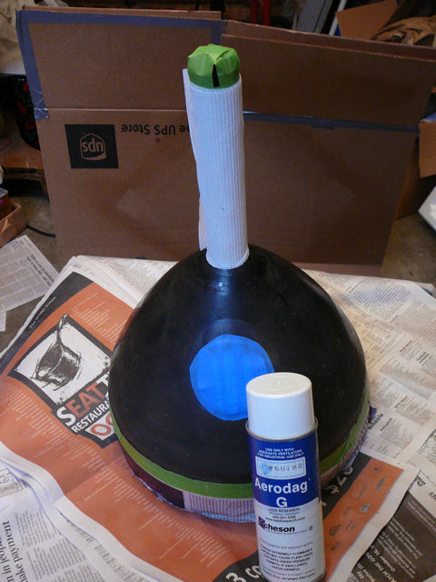
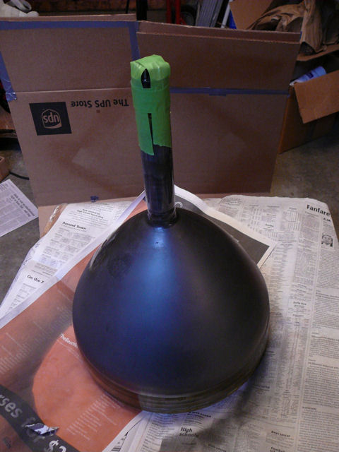
to the neck to let the adhesive dry, and then masked the picture
tube bell for spraying. It's important to leave a zone of bare glass
around the hole where the high-voltage second anode plugs into the tube.

Aerodag G is a
spray-on conductive graphite coating that dries in a few minutes. I applied two coats for good measure.
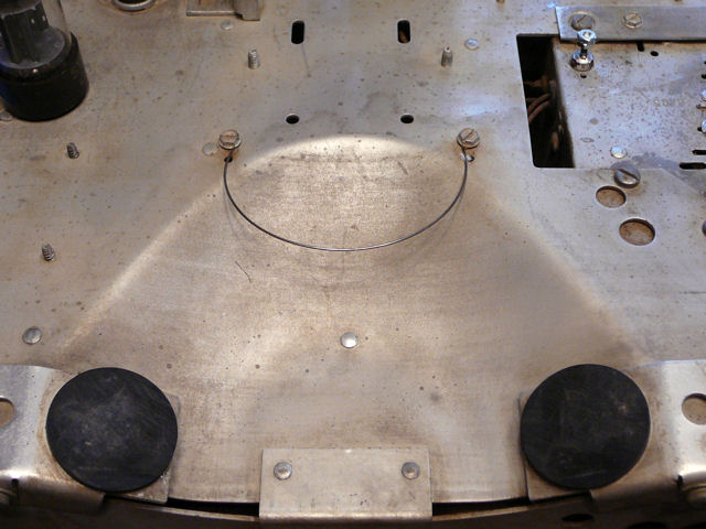
Let's not forget the place where the aquadag connects to chassis ground. In this
TV, it's an arced spring across the depression where the picture
tube bell is supported.

I cleaned the spring to ensure good contact with our fresh layer of 'dag.
Replacing Resistors and Mica Capacitors
Recapping the Admiral made it operational in a crude sense, but we're far
from finished. In terms of hours spent, the chassis is perhaps half done.
Now that the TV has a healthy power supply and makes a viewable picture, I can focus
my efforts, identifying specific problems and working on the relevant circuits.
During this phase, I'll frequently be flipping the TV on its side
and back down again, to replace components and make various tests under power.
This will be easier if I substitute my little
5AXP4 test picture tube for
the big, heavy 12LP4.
I'll start with the horizontal sweep section, often the most problematical
part of any tube TV. As noted earlier, the right
edge has a bright foldover line and that screen portion is compressed:

After replacing some out-of-tolerance resistors and a couple of mica caps,
that problem has been cured.

In like fashion, I worked methodically through the rest of the television,
seeing gradual but distinct improvements as I went along.
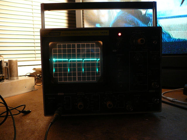
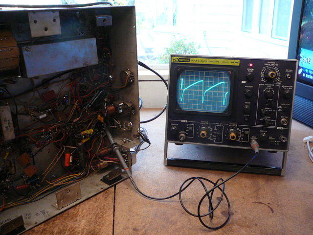
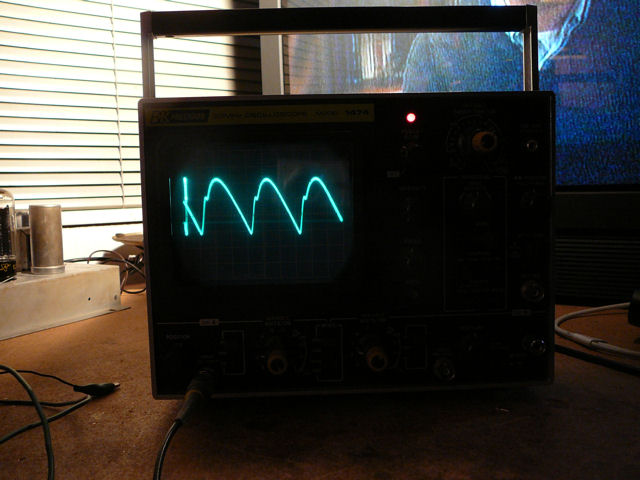
From time to time, I viewed waveforms on my oscilloscope, comparing them
to models in the Riders manual, as well as before and after some component
replacements.


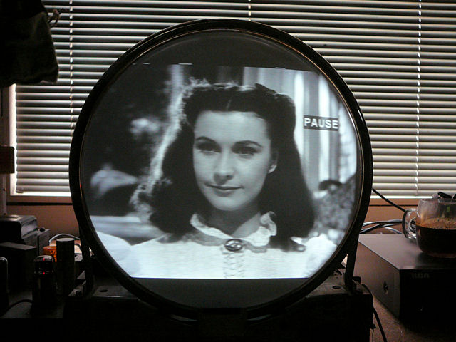
Eventually, I had gotten through the sync separator, vertical and
horizontal sweep, high voltage output, video, and AGC (automatic gain control)
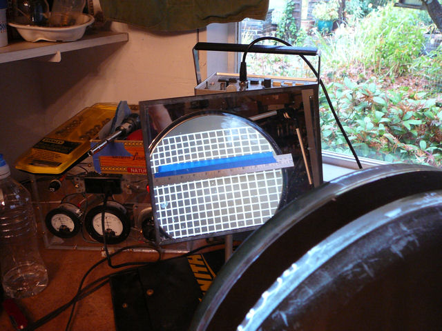
circuits. Now, the image looked good. Here's a photo of the screen at this stage,
along with the very first image for comparison.
High-voltage output is one area that needs no improvement. I had finally
replaced those two resistors under the 1B3GT rectifier socket, but
even before I did so, the HV measured 11 kilovolts, a good operating
voltage for the 12LP4 CRT.
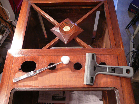
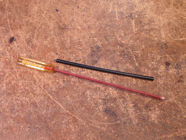
Adjusting Individual Channel Oscillators
Nearly every old TV can benefit from adjusting the
individual oscillators for each channel. This is usually done from
the front of the tuner, using a nonconductive
screwdriver with a long, thin blade. Here are two tools that I use for such jobs:

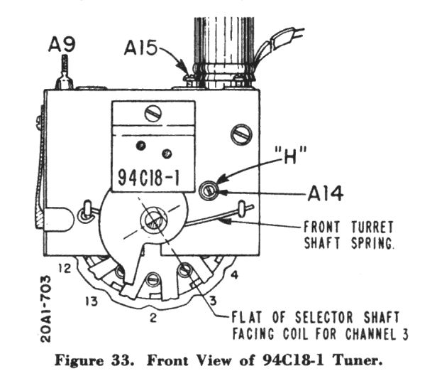
This can be done at any time after you have a good picture on the screen.
You set the fine tuner to the midpoint of its range and then switch to the
desired channel and adjust its oscillator screw through a hole in the front of the tuner,
moving it very slightly until you have the best picture (and if your audio is working,
best audio).
In this diagram from Riders, the adjuster screw is labeled A14:

In this case, I had great video and nonfunctional audio, so I adjusted each
channel for the best picture. Audio alignment would come later, as you'll read
below.
Debugging the Audio Section
When I first powered up the TV, it had been completely silent. After completing the basic
recap, I could hear a very faint signal with the volume turned to maximum.
Something was obviously wrong.
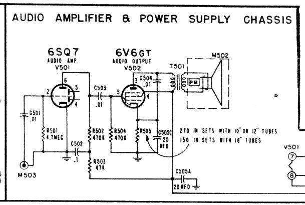
I began by checking the audio output stage, which includes the 6SQ7 and 6V6 tubes located on the
small power/audio subchassis.

When I injected a signal from my HP 200CD audio generator at the
input (M503, above), the sound boomed out loud and clear. No problems on that end!
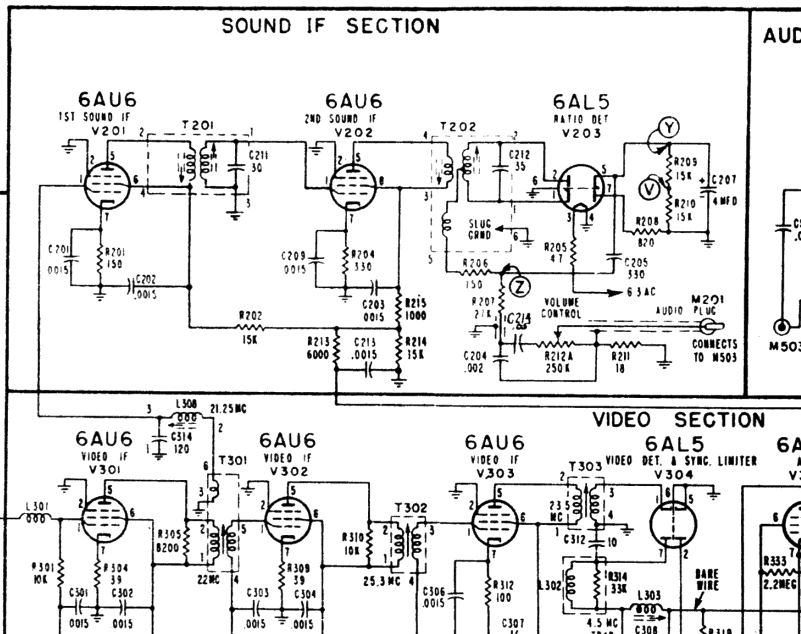
The flaw must be somewhere upstream of that point, in the audio section on the main chassis.
This includes two 6AU6 IF amplifiers and a 6AL5 ratio detector.

It's not unusual for an unrestored split-sound TV to present weak audio. Each signal
chain—video and audio—has its own IF (intermediate frequency) amplification stages
and their alignment can diverge as aging components change in value.
Sometimes, a quick tweak to the audio alignment brings the sound back.
To try this, you set the fine tuner to make the best video
quality and then align the audio to make the best sound at the same point.
This trick assumes a reasonable picture in the first place, so I had deliberately
ignored the audio until I was happy with the video.
Voltage checks of the three tubes in this section revealed no surprises, so
I ran through the audio alignment procedure in the Riders manual,
using a signal generator and VTVM (vacuum tube voltmeter). Later in this
article, we'll look at that process in more detail.
The result was disappointing. When alignment is the only problem in an otherwise
healthy IF section, you'll see obvious peaks on the meter and
the output will improve step by step. In this case, it was
hard to find any sort of peak and the alignment produced very
little improvement.
This section doesn't have many failure-prone components in the first place—only
one electrolytic and two paper caps—and those had been replaced in the basic recap.
I checked all of the coils and transformer windings for continuity, and even checked the
signal connection from the first video IF to the audio chain. Nothing
wrong there. Replacing a couple of out-of-tolerance resistors kept my hands busy
but didn't improve the audio, either.
So far, I have confirmed that many parts of the audio system work normally.
The signal is being detected and the fidelity even sounds reasonable. It's just terribly faint.
There's a kink somewhere in the garden hose, but I haven't found it yet!
Replacing Mica Capacitors Inside IF Transformer Cans
Having eliminated other obvious suspects, I removed the second audio
IF transformer (T201 in Riders) to check the little mica capacitor inside (C211).
It's common in the radio world to replace these hidden caps, which fail
often in certain radios. I hadn't needed to check them in a TV
before, but there's a first time for everything.
(In this case, I removed the transformer completely to replace this little capacitor.
In a later project, I tried an alternate approach: removing the transformer can and
leaving the transformer in place. You can read about that alternate method in my
Admiral 24A12 restoration article.)
Removing the IF transformer requires unsoldering several leads from the
terminals underneath and then freeing the clips or nuts that hold the transformer can
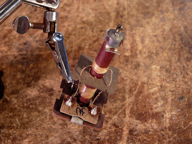
to the chassis. Here, you can see the transformer's underside before removal:

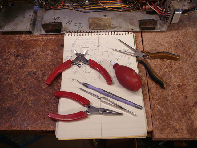
A little number is stamped in the phenolic transformer
base next to each terminal. In the next photo, I have sketched a diagram of the
connections and gathered some necessary tools. The bulb solder sucker is handy for
cleaning solder from joints and the stainless steel dental
pick is useful for loosening wires.

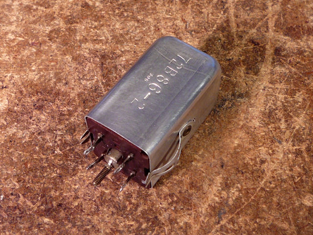
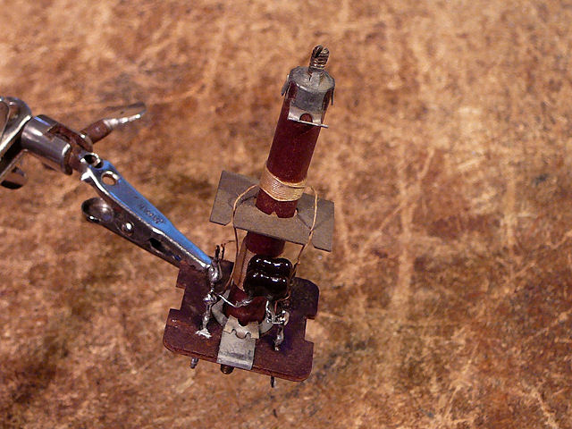
In the following photo, the IF can has been removed. You can see the terminals and screw
adjuster that were visible from underneath, as well as the springy clips
that fit into slots in the chassis.

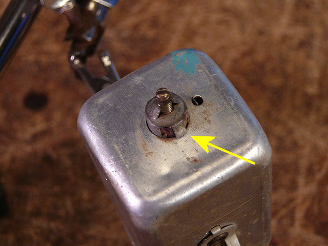
To remove the transformer from the can, depress two little retaining
tabs on the sides of the screw adjuster on top. Then the transformer
slides out the bottom.

In the following photo, transformer T201 has been removed from the can. Capacitor C211
is a sheet of mica, stamped 30 to indicate 30 pf.

(The Riders manual gives the values of these transformer caps but the Sams manual does not.
For this TV, Riders provides more details and better version coverage, although the Sams photos
are handy for locating components.)
Use care when replacing this type of cap. You don't want to wreck the hair-thin
transformer wires. The next photo shows my replacement; I wired two new
capacitors in parallel to get the right value.

Replacing that capacitor made an instant, dramatic improvement in the volume, as I found
by doing a quick by-the-ears alignment. At last, I had found the kink in the hose!
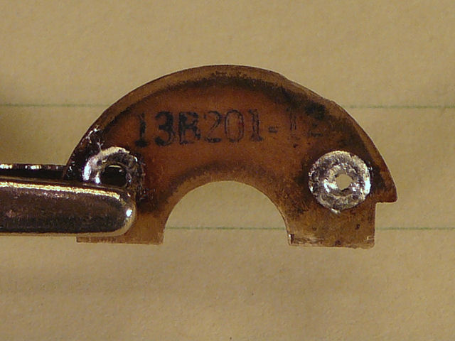
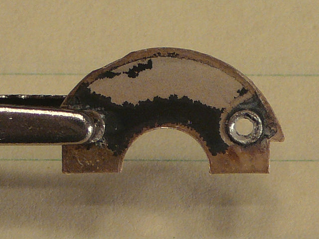
The ratio detector transformer (T402) is fastened with nuts rather than clips and its mica
capacitor (C212) is semicircular rather than rectangular.


The tiny capacitor is about as wide as my fingernail. It is stamped with a part number
rather than a capacitance value.


The black discoloration looks like silver oxide. Many of these simple caps
have a mica dielectric between pads or layers of silver. They fail when
metal migrates through or across the mica, causing leakage or short circuits.
I replaced the 35-pf cap with two 18-pf caps wired in parallel. A difference of
1 pf (36 vs. 35) is only 3% of the specified value, close enough to work in
this application.

After reinstalling the second transformer, let's do another alignment, looking
at more details this time.
Aligning the Audio Section
Although it's possible to do a crude alignment by ear while listening to
a station or test signal, the full-dress procedure in the service manual uses instruments.
Here's the Riders procedure for aligning the audio section with a signal generator and VTVM
(vacuum tube voltmeter):

Alignment requires some setup, so be patient and plan to spend some time at it.
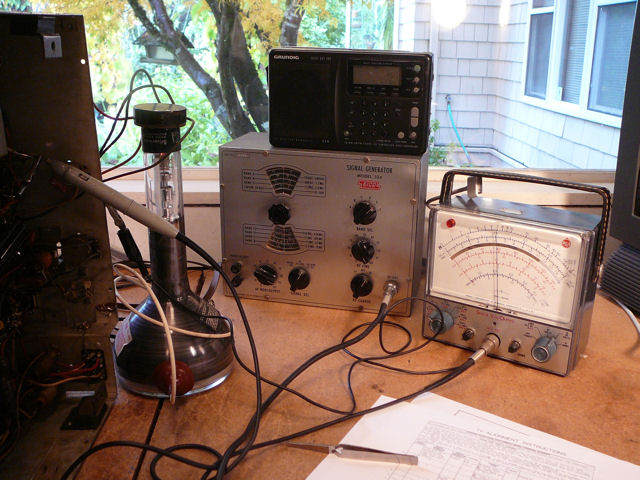
In the next photo, I'm ready to begin. The IF transformers have screw
adjusters above and below the chassis, so alignment is done with the chassis on its side.

My EICO 324
signal generator has been warmed up for half an hour and set to 21.25 MHz. Sitting on top of the
generator is a Grundig shortwave radio with digital tuning that I used to double-check
the accuracy of the generator's signal. To the right is my RCA VTVM; its analog meter
with a big scale is convenient for identifying peaks and dips as I adjust the IF
transformers.
The generator's output lead is connected to a shield on the 6J6 oscillator/mixer
tube. I pulled the shield out slightly and taped it in place so that it floats
above the chassis. This is called "loose coupling."

Next, I made an RC filter from a 10K resistor and 330 pf capacitor and temporarily soldered them
to the points given in the instructions. The VTVM probe is clipped to the junction
of the resistor and capacitor.

I also taped together three 1.5-volt cells to make a 4.5-volt battery and connected
it between the chassis and the AGC bus, as described at the beginning of the
alignment instructions.
The actual alignment took only a few minutes, less time than the setup.
In this method, you watch for peaks and valleys in the
movement of the meter's needle. An analog meter is easier to
use than a digital meter, where you have to watch a stream of constantly
changing numbers.
Sometimes, I turn the meter's zero adjuster to place the needle's starting point
somewhere in the middle of a scale rather than on a zero mark.
The actual voltage is irrelevant; what you're looking for is the peak or valley,
and that may be easier to identify in the middle of a scale.
When I was done, the Admiral's audio was vastly improved.
Before, it had been weak and twitchy, with a narrow "sweet spot" on
the fine tuner where sound was heard at all. Now, it was loud and pure, and
the adjustment range on the fine tuner was broader.
Improving the Screen Geometry
My rejuvenated 12LP4 picture tube was holding up well and the TV had
good brightness and contrast. I wasn't satisfied with the horizontal
drive and linearity, however. These factors are related and I couldn't
get an optimum picture within the normal adjustment range for either control.
At this point, for instance, the image was horizontally centered
but the linearity wasn't right (squares on opposite edges of
the screen have unequal width).

I performed another round of viewing waveforms and test patterns, checking and replacing
a few more resistors and mica caps.
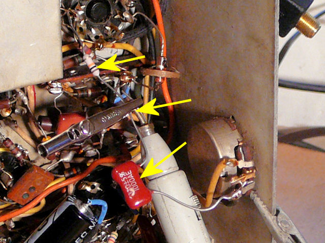
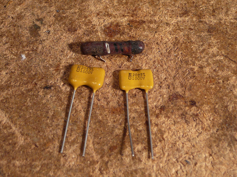
An easily overlooked capacitor is C423, mounted at the rear of the 1B3GT platform
in the high voltage cage. (The cage cover was removed for this photo.)

This cap's value is 10pf, rated for 1500 volts. It returns feedback from the flyback
transformer to the grid of the high-voltage output tube, an important function.
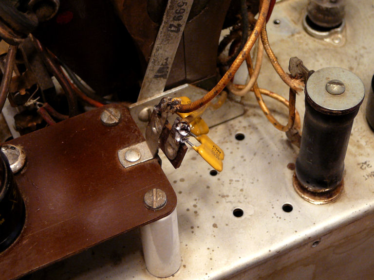
My
capacitor checker can't test anything
with such high voltage, so let's just replace it, using two 20-pf/1000-volt caps in series. (My
recapping article explains how to combine caps
to make unusual values.)


I even looked at these parts—one capacitor and two resistors—mounted
in the deflection yoke. (The yoke comes out easily after you remove the focus coil behind it.)


These components weren't directly related to any problem I was having, but I wanted to check
them for the sake of thoroughness.
Removing and then replacing the yoke and focus coil was a blessing in disguise.
After I reset the focus coil from scratch, both the centering and
horizontal linearity were improved. (Of course, the most recent component replacements
helped, too!)
After I finish the cabinet work and reinstall the chassis,
I'll touch up the settings to fit the image precisely in the mask.
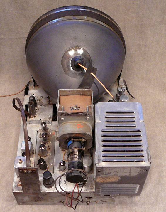
Electronics Finished!
I can't find anything else to tweak in the electronics. Let's
declare that part of the project complete. Here's the chassis at this stage:

Quite a change from where we started!
Applying New Decals: Rehearsal
While the electronic work was underway, new decals had been ordered. Creating these was
a group effort. I knew a maker of custom decals from my
RCA CT-100 restoration, but the decals on this
cabinet were quite worn and I'm not great at making cleaned-up images of such
things.
Fellow collector Bob (bandersen on the Antique Radios
forum) supplied close-up photos
of the pristine decals on his blonde Admiral cabinet, and forum member Ben (noisebox) volunteered
to transform those photos into clean, one-color images for the decal maker.
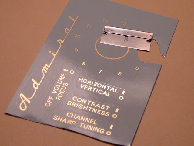
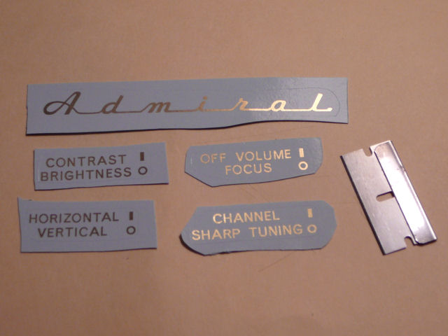
This photo shows all of the decals on Bob's blonde cabinet:

Here is one of Ben's new images, a high-res version of the big Admiral logo.

I sent the art files, along with the original decal photos for scale,
to Scott Wright
of Solidesign, who printed ten sets of decals
in metallic gold. The cost was $17 per set.

Bob had several Admiral consoles in line for restoration, so he took eight
sets and I took two. I only needed one set, but I wanted some spares in case
of mistakes. I eventually sold the unused spare set to a fellow collector.
If you need a set of these decals, contact Scott Wright
of Solidesign.
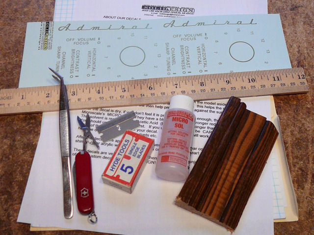
I'll practice on a piece of scrap wood, using
channel numerals that aren't needed on my TV. (It has a plastic tuner dial
in place of number decals around the tuner.) Here are the tools and supplies that I'll use:

(Earlier, I had bought a little bottle of MicroSol solution, but the Solidesign instructions
warn that Microsol can dissolve the film if too much is applied. Microsol seems best for
forming decals onto a non-flat contour, such as a tiny rivet or seam in a model. My surface was
flat and the decal adhered well without Microsol, so I didn't bother using it.)
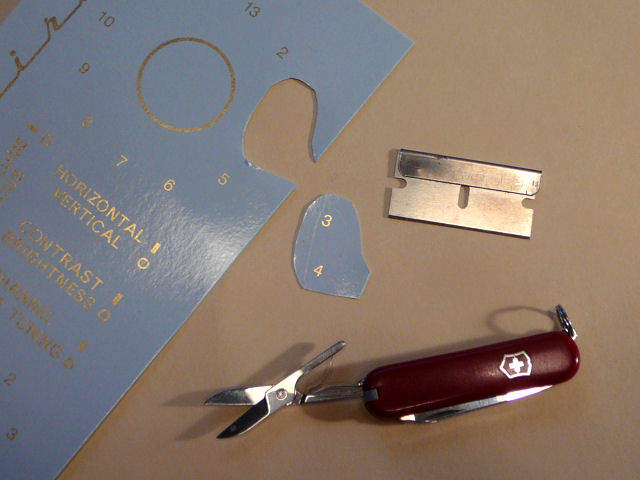
The decal sheet has two layers: a thin film on a paper backing. The maker's instructions
tell you to score an enclosing line lightly through the film, closely around the decal.
This defines the piece that you'll stick onto your surface. Then you cut out a larger piece that includes
some of the backing sheet all around. This makes it easy to handle the piece with a tweezers.
In the next photo, I have scored an oval closely around a pair of numerals and cut out a
larger piece of backing sheet around that oval:

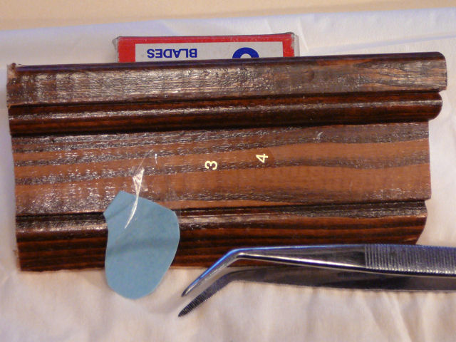
After soaking the piece in warm water for a few seconds, you remove it and scrape the
excess film off the backing outside the scored line. Then you put the piece right
next to the destination and slide the wet decal onto your surface.
While the decal was still wet, I was able to slide it around with a fingertip to position
it exactly. Then I blotted and pressed it lightly with a tissue to eliminate air bubbles.
In this photo, the decal has been applied:

(I showed the backing piece and bits of excess film to show what's left over
in the process. These will now be discarded.)
The film comprising the applied decal is extremely thin, nearly invisible except where
it has gold ink. The un-inked part will not be noticeable after I apply
clear lacquer on top of it.
Notice that the tiny grain pores in this wood finish are visible through the film.
Thin decals take on the texture of the underlying finish, for better or worse.
Applying those tiny decals was easier than I expected. The final application only takes seconds.
Handle the decal carefully when wet and don't leave it in the water too long,
lest the film float away from the backing paper. You have a limited time to position the decal
before it dries enough to adhere. Before placing the decal, you should know exactly
where you want to put it.
Applying New Decals: Game Day
I spent a long time thinking about how to apply the decals in exactly the right spots.
In hindsight, before removing the old decals, it would have been helpful to trace their
edges onto a big piece of graph paper to record the distances between the decals, as well
as their distances from the control openings and upper cabinet edge.
Lacking such a template, I looked at various photos on the computer, to deduce those
measurements after the fact.

I printed a 24C16 cabinet photo that Bob had provided and marked approximate
measurements on the printout.
Next, I scored around the decals and cut them out, leaving a little excess paper
on all sides.


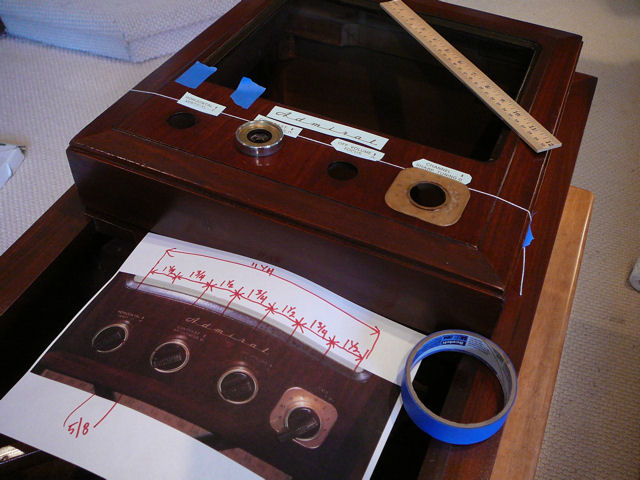
I taped a string across the cabinet face to align the lower edges of the control decals,
and then placed bits of tape to mark where their left and right edges should go. (In hindsight,
it would have been simpler to put little tags of tape on the string itself.) The
string can be nudged slightly out of the way when I apply each decal.

It was useful to have a diagram with measurements, but I really wanted some kind of guide on the cabinet itself.
It takes two hands to manage the decal when it's wet, which doesn't leave an extra hand
to mess around with rulers or templates.
In the next photo, I have placed the four control decals and moved up the string to mark the
lower edge for the big Admiral logo.

These large decals were more difficult to manage than the tiny ones I had used for practice.
Once applied, it's trickier to slide a decal into position without creating folds or (shudder!)
breaking it by stretching too hard.
Although the instructions tell you to soak the decal for 30 seconds, I found that only a few
seconds was needed. Leaving it in the water longer may allow the entire film to float up above
the backing paper. If that happens, use the tweezers to maneuver the paper backing back under
the film to recapture it. Whatever you do, don't let a floating film fold over onto itself.
If a fold develops, use the tweezers underwater to straighten it out.
At last, all of the decals were in place. Not perfect, perhaps, but good enough to
get us through airport security.

Using a string guide worked well, but that made me wonder what was used in the
Admiral factory—perhaps a thin metal jig clamped to the cabinet, with markings
to show each decal's location.
Several weeks later, I read an interesting
discussion
in the Antique Radios forum that suggested a simple and effective method: using Post-it notes
to align the decal edges.
With decals in place, I can see the end of this project. All that's left before reassembly
is to polish the safety cover and do something about that ghastly grille cloth.
Restoring the Screen Cover
The screen cover on this television is made of thick Lucite, tinted a very
pale green. A few early manufacturers used green tinted screens,
ostensibly to reduce eyestrain.
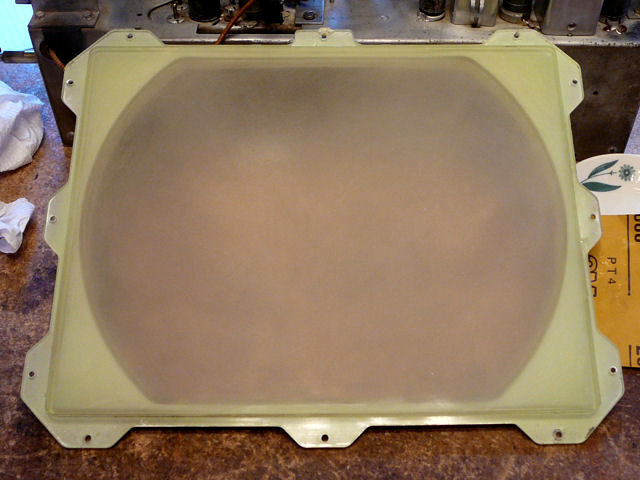
This screen cover was the worst I had ever seen. It was covered with scratches
and scuffs, far more than would result from everyday wear. Perhaps children
scribbled on it with a marker and then someone used steel wool
in an attempt to clean it. The cover also had a few melted spots that might
have come from hot cigarette ashes.
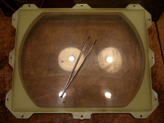
This photo actually makes the cover look better than it was at that stage. (I laid
a tweezer on the cover to make my camera focus on that surface rather than
on the reflected light.)

I normally wouldn't use sandpaper on a Lucite cover, but the deep scratches
left no alternative. Here is the cover after I wet-sanded the worst areas
with 800 grade paper.

Sanding with water or another lubricant prevents buildup of the sanded
material and helps you sand evenly without scoring.
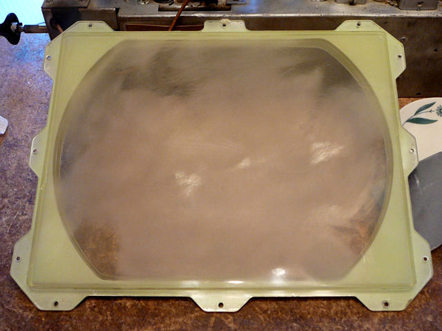
I followed that sanding with a couple of finer grades. The next photo shows
the cover after wet sanding with 2000 grade paper. It has become nearly opaque,
but we'll clear it up, eventually.

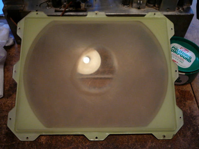
I then switched to rubbing compound. The next photo shows where I have
begun polishing in the center. The opaque screen is already clearing.

In the next photo, I have switched to Novus Plastic Polish #2
and begun polishing another circle in the center. The cover is regaining clarity
by stages.

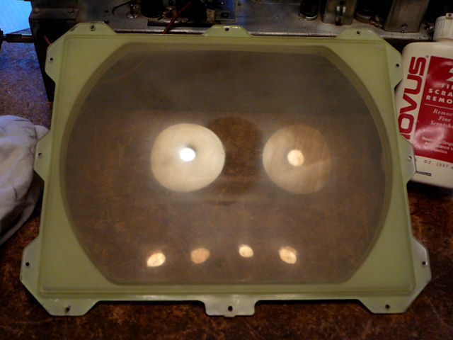
I could still see swirl marks after one application of Novus #2, so I got
out my jug of Novus #3, which is slightly more abrasive.
The final polishing took
a couple of hours, alternating between Novus #2 and #3 and constantly
changing to new, clean cloths. At last, the cover looked clear and smooth.

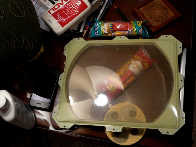
It took time to restore the screen cover, but I'm glad that I invested
the effort. After spending many hours on the electronics, it would have been
frustrating to watch TV through a cloud of scratches and cigarette burns.
Restoring the Grille Cloth
In the course of this project, I obtained a second speaker board with cloth from a
fellow collector who was parting out an Admiral TV/radio/phono console.
The combo board was a bit wider than mine, but at least it was not torn or
heavily stained.
The "new" cloth was also quite faded, so I couldn't simply cut down the
board and install it in place of the old one. The color would be wrong and the
unfaded portions of the cloth wouldn't match the diagonal wooden bars on my cabinet.
Since I had two cloths to play with, I decided to try something new:
removing a cloth from the board, washing it, and reapplying it. If this plan
failed, I still had my original as a fallback.
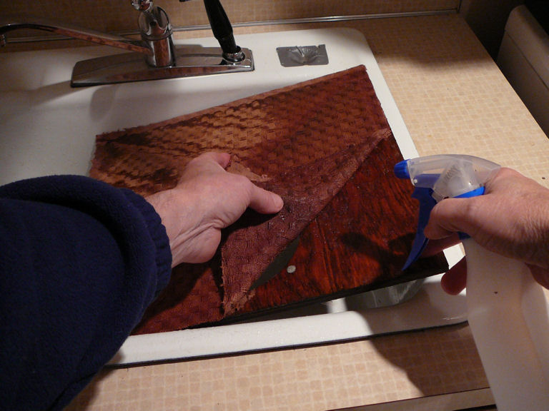
Experimentation revealed that the glue was water soluble,
so I carefully removed the old cloth from
the board, soaking the cloth and adhesive with water from a spray bottle and
gently peeling away the cloth.

The front of this cloth had faded but the reverse was much darker. Just what I was hoping!
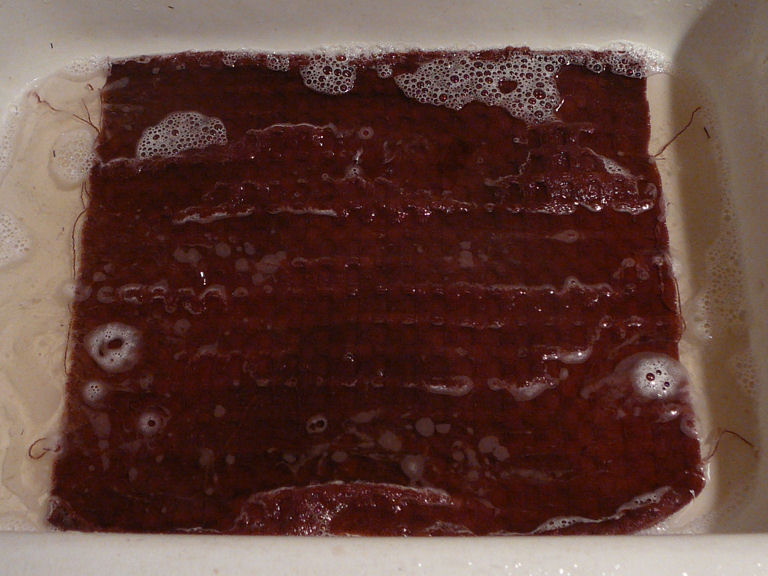
Next, I soaked the cloth in cold water with a little Woolite, gently
agitating it from time to time. I would not recommend using hot, or
even warm, water on an old cloth. It's going to shrink anyway, but
you don't want to shrink it more than necessary.

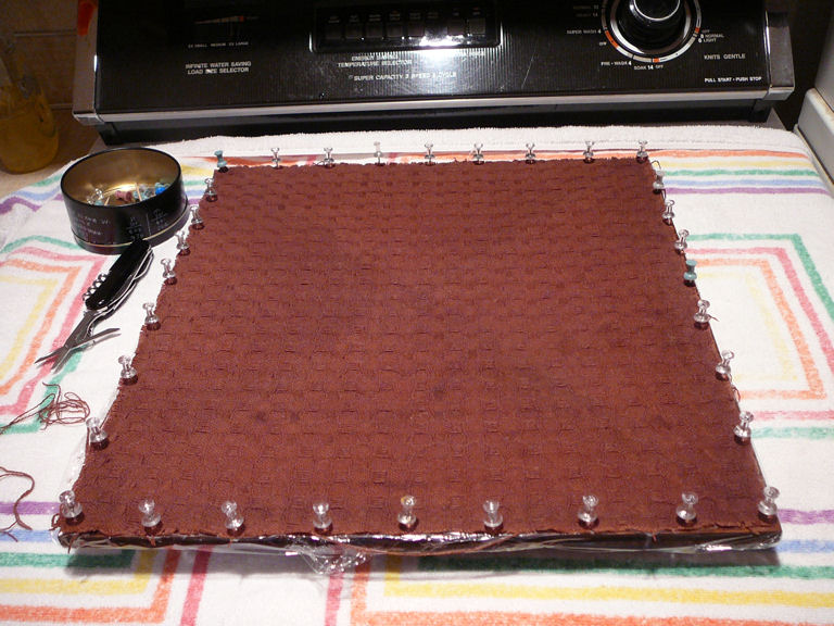
After rinsing the cloth several times, I blotted off the excess water and stretched
it back onto the board, using pins to secure the perimeter. The board was still wet
but I had covered it with plastic wrap before securing the cloth.

I set it aside to dry overnight at room temperature.
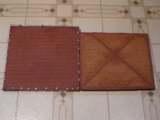
The next day, a comparison of the two cloths shows how light exposure has faded my
original (on the right). The reverse side of the washed cloth still retains
plenty of color.

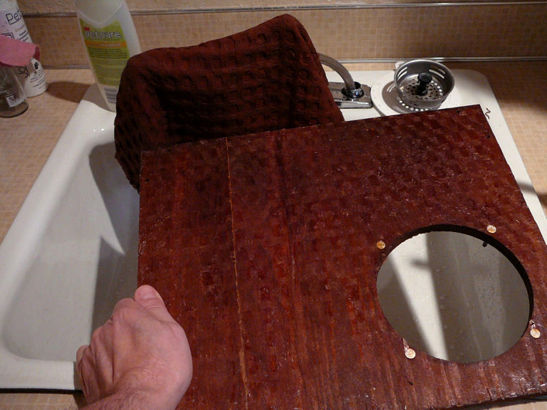
Back to the sink! Whether or not I use the new cloth, I'll need to remove the old one
from its speaker board.
The next photo shows the cloth and board after removal. This
one was applied with much more glue than the other. Even after being soaked for
more than half an hour, and peeling away all the cloth, you can see the cloth
pattern in a layer of glue residue.

This fabric was also dirtier than the first. By the time I was half done removing it,
the bottom of the sink was covered with dark yellow animal urine that had been
soaked out by my spray bottle. Yuck!
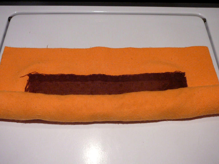
It took longer to wash this cloth, not only because of stains, but because it was
saturated with glue in many areas. At last the washing was done. I blotted and
straightened the cloth by rolling it tightly in an absorbent towel.

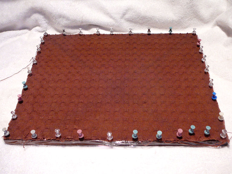
Here's the second cloth pinned out to dry. I stretched the torn corner (at lower right)
a little harder than the rest, hoping to get most of the damaged part into the margin
where it will be covered by the cabinet edge.

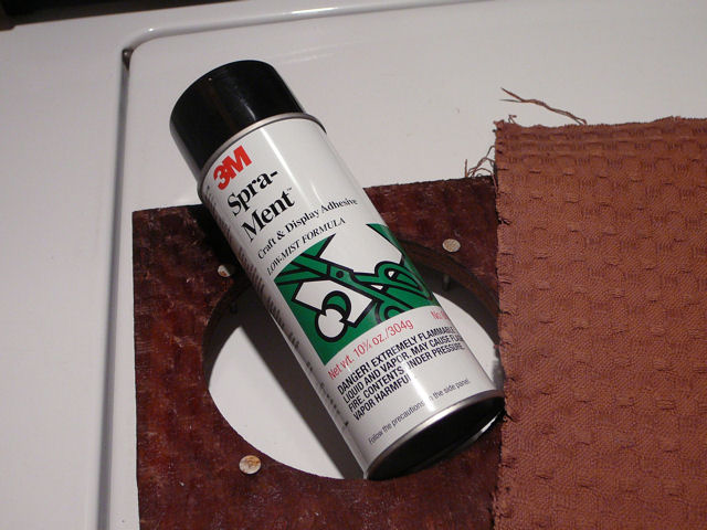
I left the pinned cloth to dry overnight. When it was ready, there was really no
comparison. The first cloth was preferable in every way, with deeper color and
no residual stains. I fixed it to the board with spray adhesive and trimmed the
excess.

Before remounting the speaker to the board, I added spade connectors to its
terminals, to simplify future service.

I also pierced the cloth with a smooth awl
at every place where there is a hole in the board for a mounting screw. These
guide holes prevent problems with a wood screw twisting up some threads in the cloth.
Reassembly
After months of on-and-off work, reassembling the finished TV was anticlimactic.
I touched up the vertical height and linearity to fit the mask, and it was done.
If you look closely at that photo, you'll see that I was missing two of the
knobs that appear as a brass circle around two dark, smaller knobs. I later
got some replacements from a fellow collector.
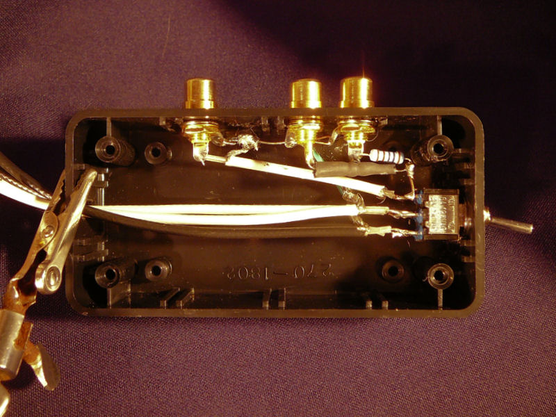
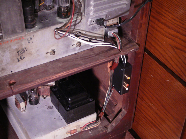
Adding an Audio/Video Adapter
After the restoration was done, I decided to build a simple audio/video
adapter for the Admiral. The adapter bypasses the TV's tuner, audio,
and IF (intermediate-frequency) sections and injects standard A/V
signals at the audio and video amplifier tubes.


The adapter produces noticeably better video and audio than using the
TV's antenna inputs. You can learn how I built it in the
accompanying article.
Final Thoughts
This 24C15 console is a nice performer, like my other Admirals, the
19A12 tabletop and
24A12 console.
This is a fairly simple TV to work on, with an open layout and nothing
startling in the way of circuitry or features. The project took longer than
usual because this set was in bad shape, not because Admirals
are tricky.
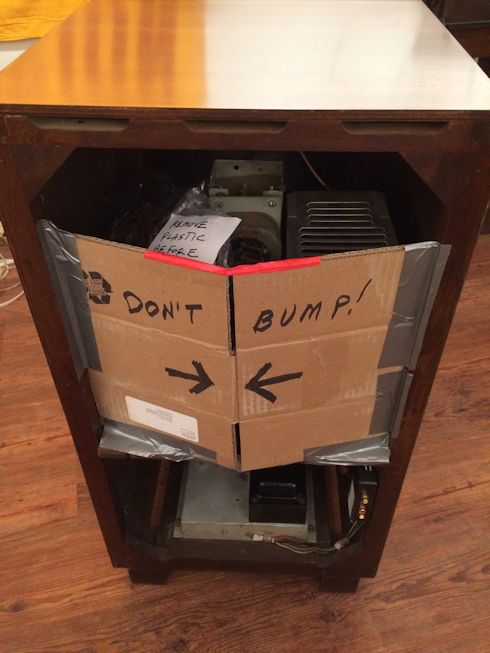
In October, 2018, I sold this set to a collector who lives in Nashville. His band
was touring in our area and they picked up the TV on the way, transporting it all
the way from Washington to Tennessee in their tour bus. Before turning it over, I
made sure that everything was well secured in the cabinet. Since the TV lacks
a back cover, I fashioned a temporary back to guard against bumping the neck of
the picture tube during that long road trip:
We also wrapped it in a couple of padded quilts (actually, old mattress covers)
to protect against scuffs and minor bumps on the road. I held my breath during the next week,
while the band completed their tour by way of Portland and Los Angeles. Happily, the TV
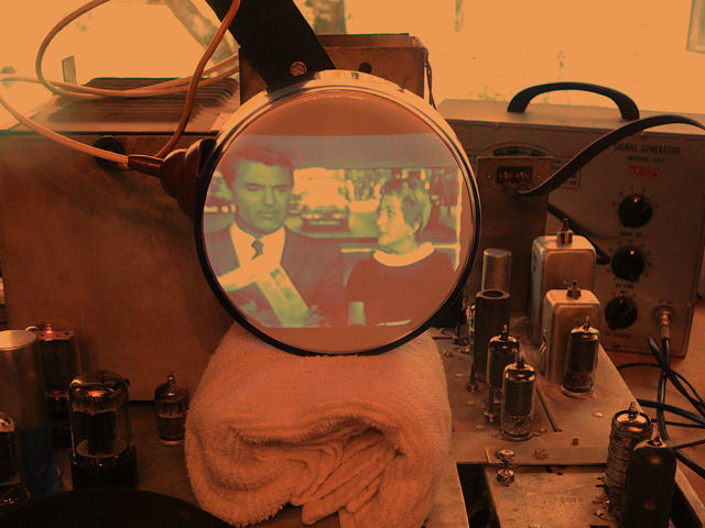
survived the long trek in working order, and the new owner sent me this picture of the Admiral
playing in its Nashville home:

|