Admiral Model 19A12 (19A11) Tabletop Television (1948)


This Admiral model 19A12 television was a big seller in 1948.
Attractively styled and inexpensive, it was one of the better performing
7-inch TVs of its day.
Description
Admiral sold this tabletop TV from 1948-1949. It was priced at $169.95 as seen in this dealer
brochure at the TV History website:
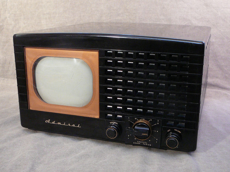
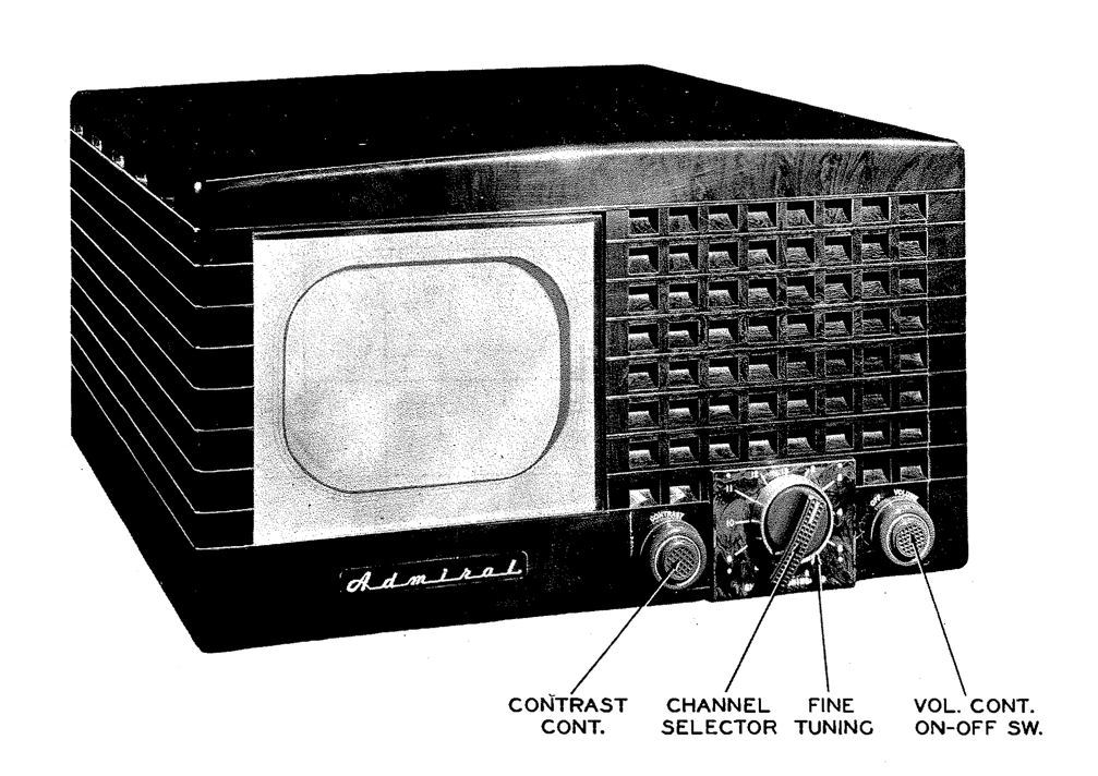
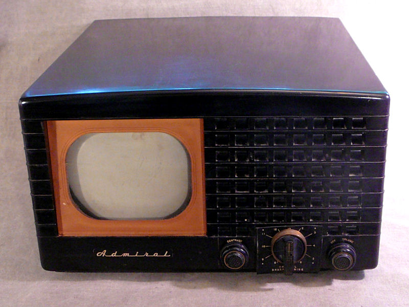
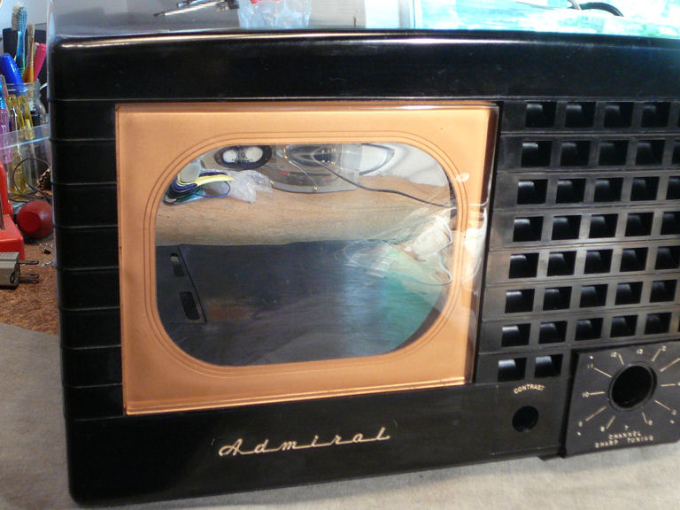
My cabinet is made of black Bakelite with a gold colored screen bezel.
To the right of the screen is the checkered speaker grille. Here is
the restored television:
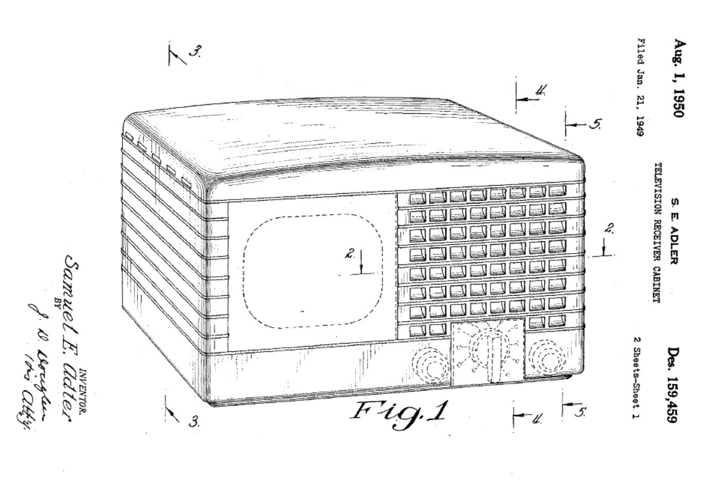
Admiral was issued US design patent
D159459 for
this cabinet. The second image is the patent drawing:


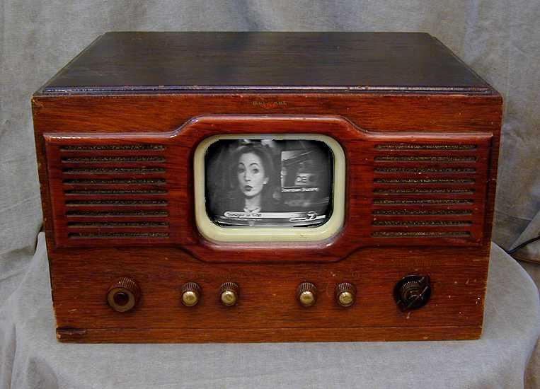
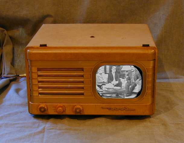
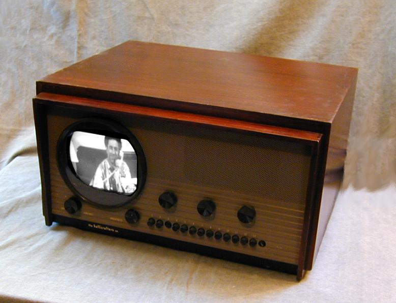
In addition to the black cabinet (model 19A12), Admiral offered this TV in brown Bakelite
(19A11) and maple wood (19A15). A variant of the Bakelite grille with concentric squares
is sometimes called the "Chinese."
This television was very popular in its time and many have survived,
making this an easy set to find. I would not pay more than $100-$150
for an unrestored one that is complete and unmolested.
This is my sixth 7-inch TV. The others are a
National TV-7W,
Motorola VT-73, and Hallicrafters
models 505,
T-54,
and 514.


In build quality, I'd rate this Admiral near the top of the pack, along
with the National. It has a transformer power supply, unlike the other series-string
sets, and it uses a sturdy turret tuner rather than the less costly
wafer or pushbutton types.
The electronics are conventional, using an RF high-voltage supply
to drive the electrostatically-deflected 7JP4 picture tube. Like other 7-inchers,
the 19A12 lacks features such as DC restoration that were furnished in premium
televisions like my DuMont RA-103.
The 19A12 has 18 tubes:
| Tube |
Type |
Function |
| V1 |
6AU6 |
Audio IF |
| V2 |
6AL5 |
Ratio Detector |
| V3 |
6SQ7 |
Audio Amplifier |
| V4 |
6AS5 |
Audio Output |
| V5 |
6AU6 |
1st IF Amplifier |
| V6 |
6AU6 |
2nd IF Amplifier |
| V7 |
6AU6 |
3rd IF Amplifier |
| V8 |
6AL5 |
Video detector / AGC |
| V9 |
6AU6 |
Video Amplifier |
| V10 |
5Y3GT |
Low Voltage Rectifier |
| V11 |
6SN7GT |
Sync Separator / Vert Oscillator |
| V12 |
6SN7GT |
Sync Amplifier / Horiz Oscillator |
| V13 |
1B3GT |
High Voltage Rectifier |
| V14 |
6V6 |
High Voltage Oscillator |
| V15 |
6SL7GT |
Balanced Vertical Oscillator |
| V16 |
7JP4 |
Picture Tube |
| V701 |
6AG5 |
RF Amplifier |
| V702 |
6J6 |
Oscillator & Mixer |
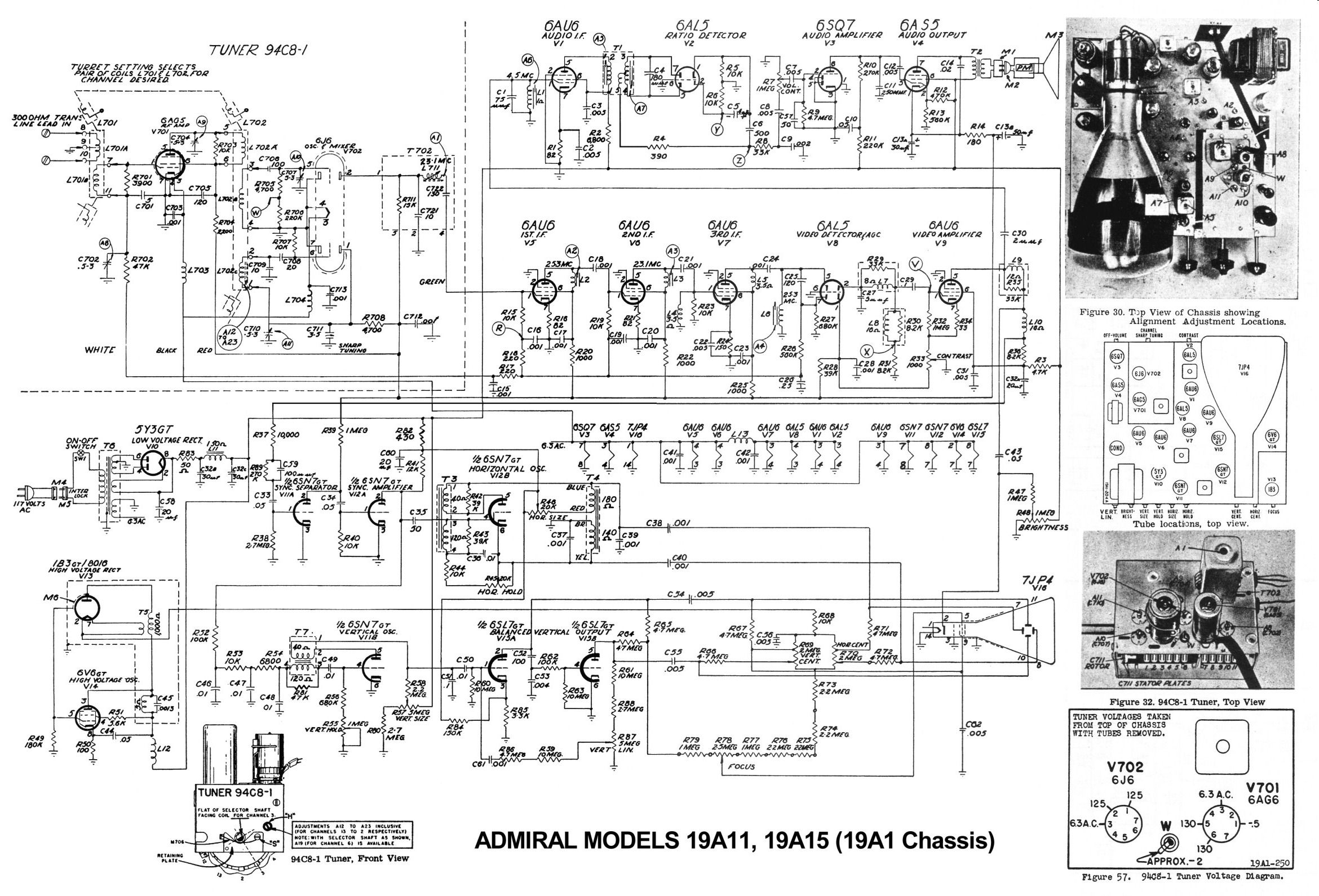
Models 19A11, 19A12, and 19A15 use the 19A1 chassis. You can download the Riders
service manual from the Early Television Foundation
archive.
The Sams service manual is Set 59, Folder 2, available from the Sams
website.
My TV is a later version that differs slightly from the Riders and Sams
manuals. It has a vertical linearity control on the back panel
and an extra 6KV-rated capacitor connected to the vertical centering
control. These additions are shown in the Wallace Teleaide schematic that appears below.
To save it on your computer, right-click the icon and choose Save Target As.

This article uses the part numbers given in the Riders and Wallace schematics.
Finding an Admiral 19A12
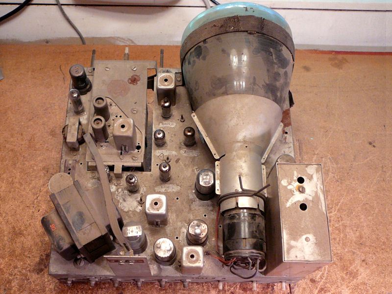
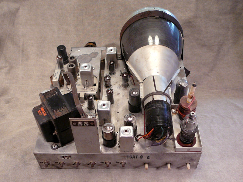
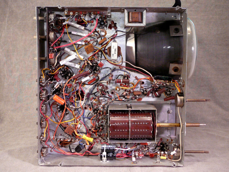
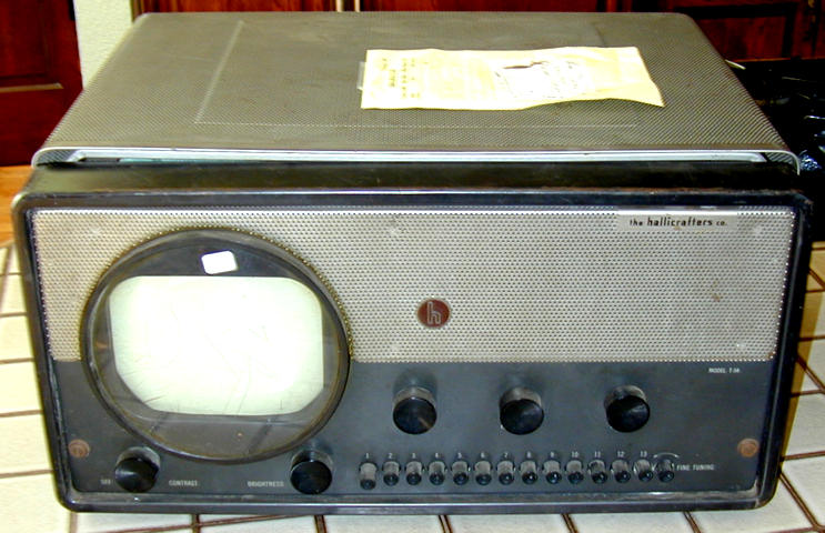
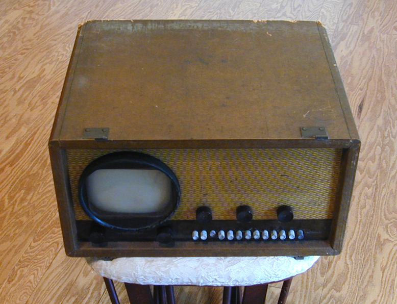
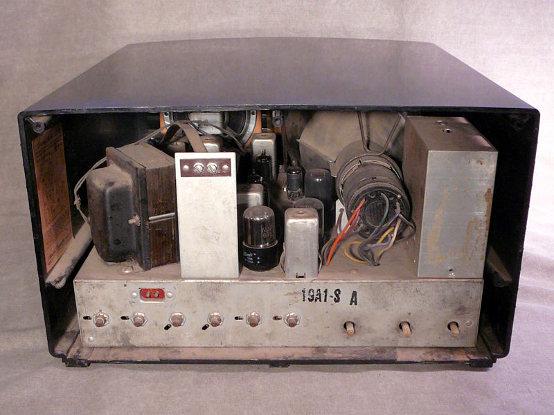
I bought this TV at a Seattle swap meet in August, 2012. Here's the set as found:


In the rear view, the power transformer stands at the left and the
high voltage compartment at the right.
My set was missing the back cover and power cord, but otherwise it looked
complete and unabused. Best of all, the cabinet was free of any cracks or
deep scratches. Since I found this TV locally, it didn't have to
survive the hazards of shipping. If you buy one of these at long distance, I
strongly recommend removing the chassis and shipping the television in
two cartons. Otherwise, the brittle cabinet will likely be smashed to pieces.
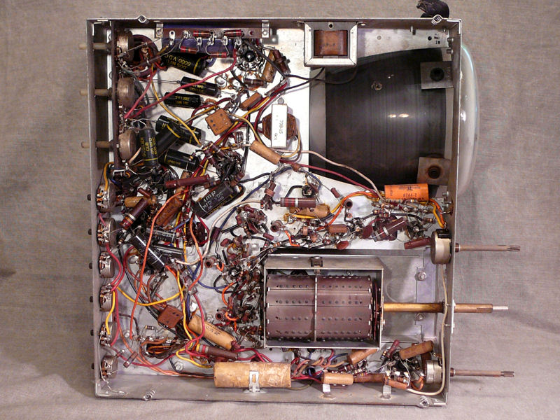
Underneath, I could see that this set was serviced, or perhaps
you would say partly restored, some years ago. Mixed in with original
capacitors I see several newer ones. Based on the types used,
I'd guess that work was done in the 1960s or 1970s.
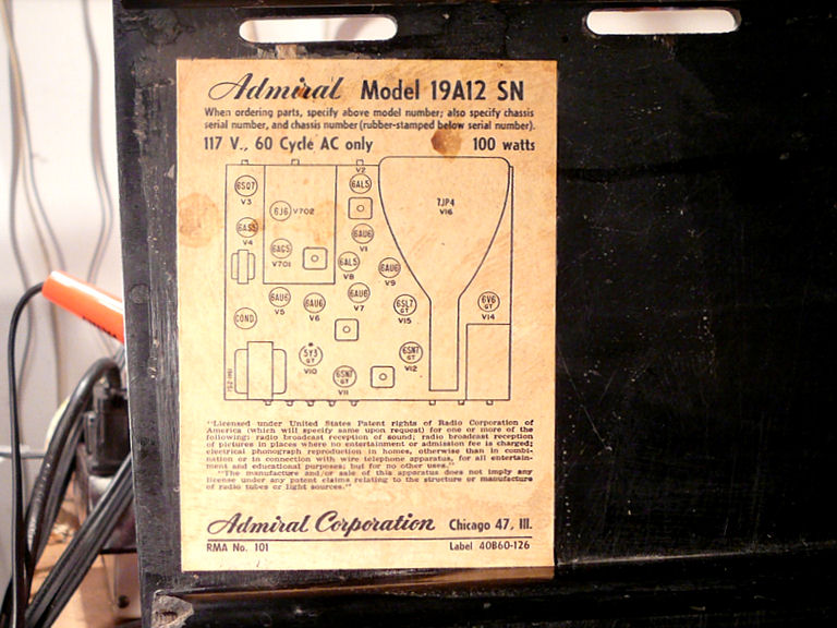
The label gives the model number and tube layout.

Cleanup and Tube Testing
As always, the restoration begins with cleaning, visual inspection, and
tube testing. You can read more about these basic tasks in the article,
First Steps In Restoration.
This TV cleaned up easily.


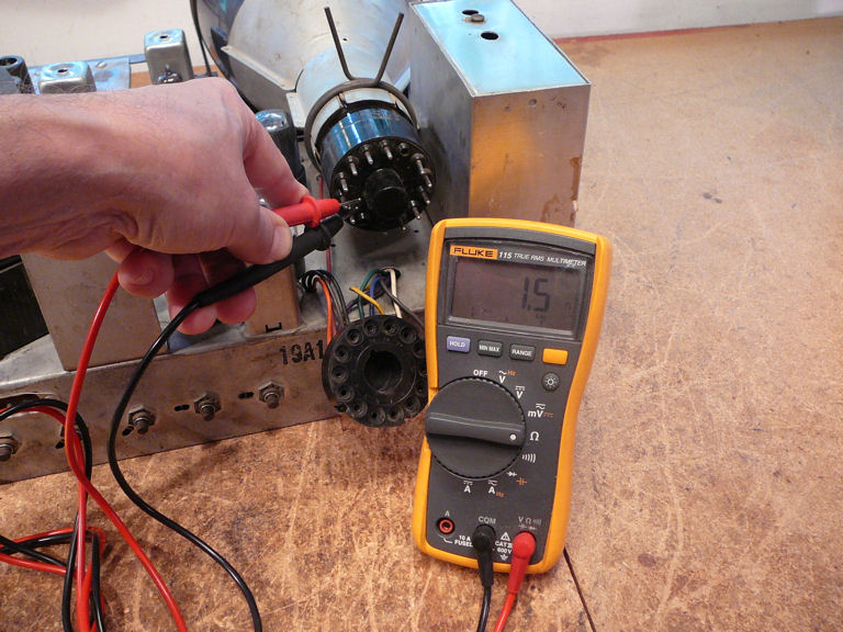
A quick continuity check of the picture tube's filament tells me that it is
intact. My Sencore CR70 tester is able to test the emission on a
7JP4, but this quick Go sign is sufficient here.
I'll learn soon enough whether the CRT is weak or strong.

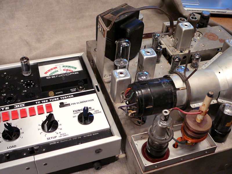
As often happens, all except one of the small tubes tested good. Here's a good one:

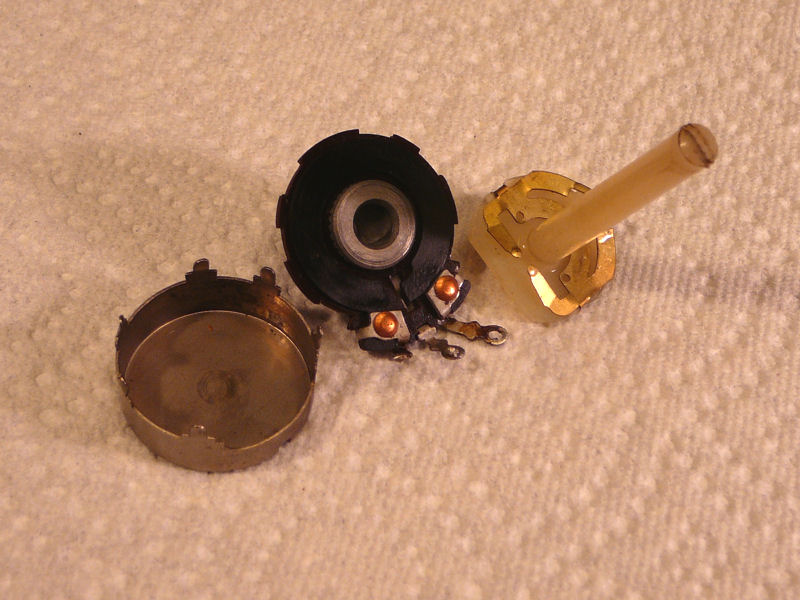
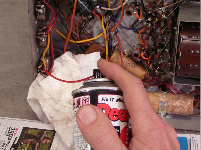
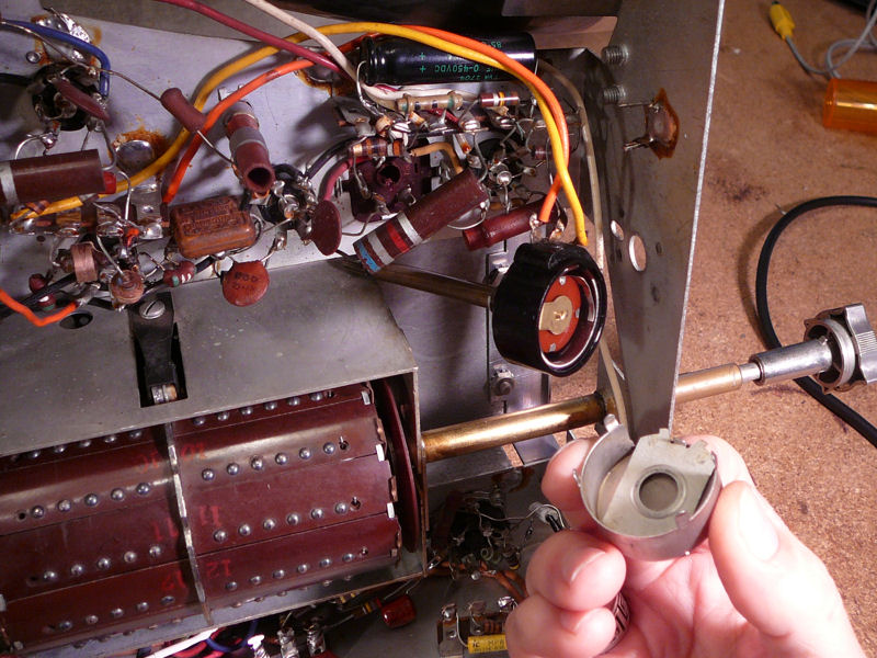
Here, I'm cleaning the potentiometers on the chassis
rear panel:

Three of the rear potentiometers carry high voltage and have shafts made of
nylon to prevent shocks. One of them, the Focus pot, was
impossible to turn. Opening it up, I didn't find any damage or
petrified lubricant.
Cleaning and lubrication failed to free the shaft. Perhaps the nylon had
swollen over the years, or the surrounding metal bearing had done so, or a little
of both. I lightly sanded the shaft and reamed the bearing
until the pot moved smoothly. Adding a small amount of lubricant, I reinstalled it.
I also replaced the two 1-megohm resistors attached to either end of the
pot, since they had drifted about 30% over the specified value and
they were already half disconnected.
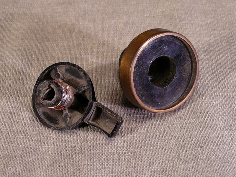
Inspection didn't reveal any more problems apart from this funky tuner
knob:

The shaft cracked at some time in the past and it was repaired by wrapping
copper wire around the shaft and soldering it. Although
the knob works, it's a little sloppy. I'll
reinforce it with epoxy and try to improve the fit.
After a little more sprucing, including treating rust spots with Naval Jelly,
the chassis looks more civilized. Let's get busy on those old capacitors.
Replacing Capacitors
Recapping this television was largely routine. You can read about that
general process in my recapping article.
The simple design of the 19A12 employs only six electrolytic capacitors,
and this photo shows how I dealt with five of them.

The aluminum can on the left originally held three electrolytics. I have restuffed
it with two new caps, and the sawed-off end is held back on with a rubber band while the epoxy
cures. The third cap wouldn't fit in the can, so it will be discreetly
mounted under the chassis. In the Riders/Wallace schematics, these caps are C32A, C32B, and C32C.
To the right you can see the old cardboard case that contains two electrolytics (C13A, C13B).
Above it you can see where I installed the replacements, strapping them
to the original bracket with a stout nylon tie.
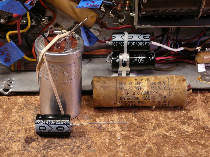
The Achilles heel of every 7-inch television is its bank of high-voltage capacitors.
Rated at 6,000 volts, these deliver current to the picture tube's horizontal and
vertical deflection anodes and they are invariably bad if original.
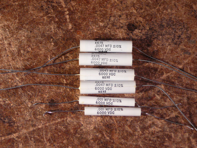
The best capacitors for this application are tubular caps like those
shown below. You
can obtain them from Just Radios.

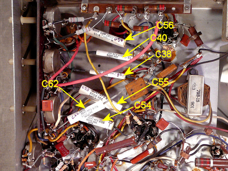
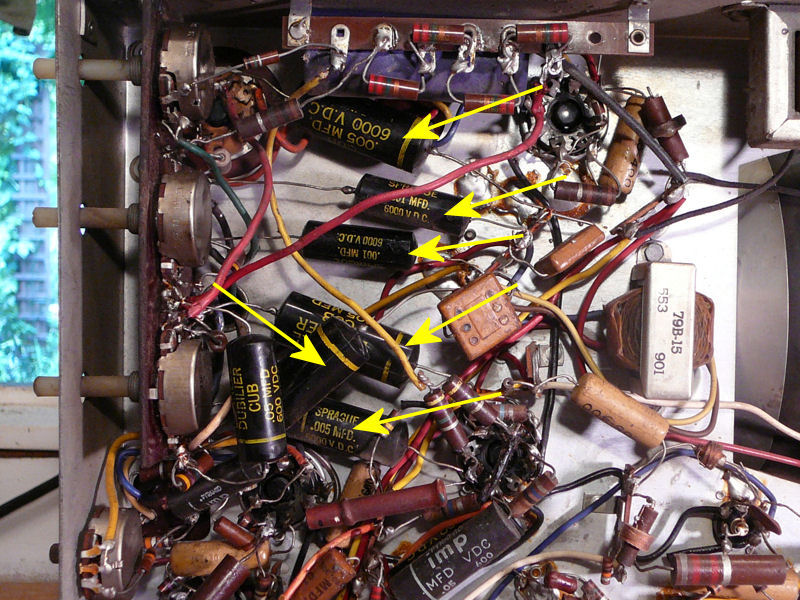
These photos show the six 6KV capacitors used in my television:

In the versions of this TV documented in the Riders and Sams schematics,
only five of these capacitors are shown: C38, C40, C54, C55 and C56.
My set has an additional 6KV capacitor, labeled C62 in the Wallace schematic.
I believe that the original 6KV caps were paper and the "Black
Beauty" molded paper types seen in the first photo were installed during a
later restoration. Not only are the Black Beauties perhaps 40 years old,
but this type was terribly unreliable in the first place, so I didn't hesitate to replace them.
If you look very closely in the first photo above, you'll see a dark blue object
partly hidden behind a terminal strip at the very top. This was an electrolytic
in a cardboard case, and it was an extra, not shown in any schematic.
A little tracing showed that it was electrically parallel with the power-supply electrolytics
that are physically located on the opposite side of the chassis. No doubt the
previous repairman added it in an attempt to cure failing caps
in the power supply.
That kind of quick fix isn't kosher by my standards. You should never connect a new capacitor
in parallel with an old one, since a short circuit in the old one will defeat
your purpose. The extra cap was superfluous
now that I had properly replaced the other electrolytics, and anything that old had
probably dried into garbage anyway, so I removed the unwanted guest and tossed it into the discard pile.
First Image
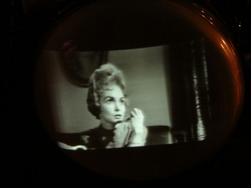
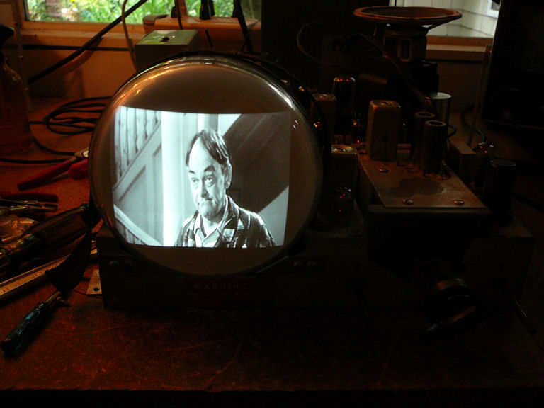
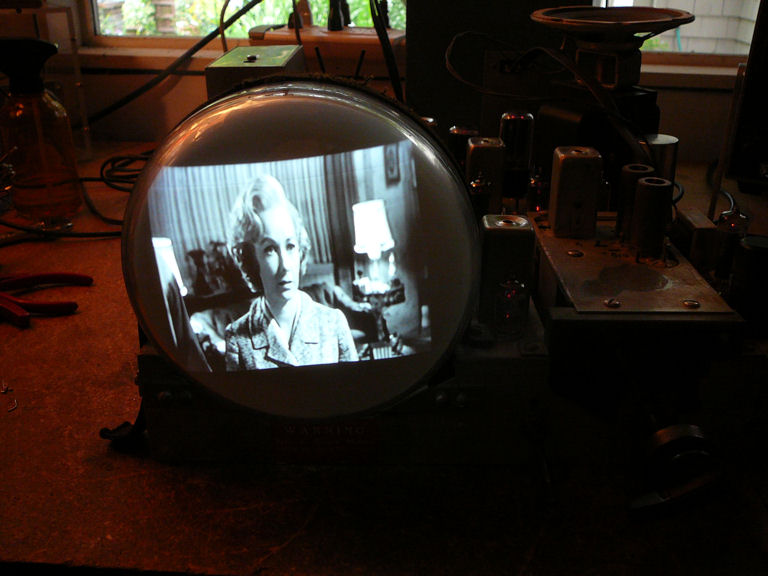
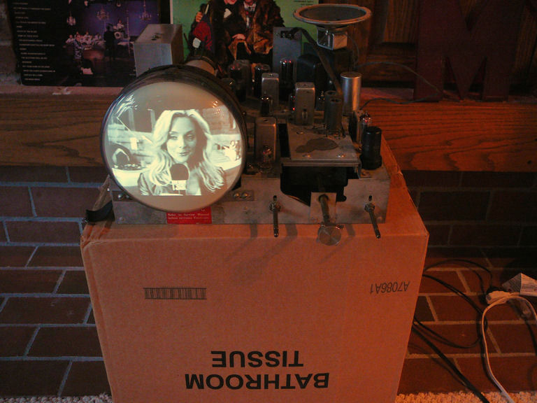
Just for kicks, after replacing the electrolytics and the bank of high-voltage
capacitors, I gave the television a try. Here's the result:
Yippee! The image is faint, shrunken, and tilted, but it's coherent and
stable, with good contrast. Not bad for only a couple hours of work.
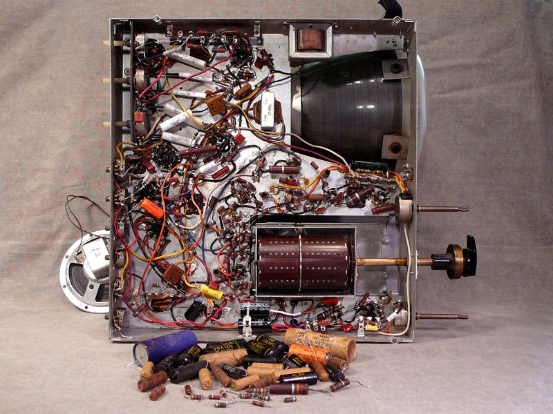
Completing the Recap Job
This inspired me to keep plugging away. I finished replacing the capacitors
and also replaced some out-of-tolerance resistors in the sync and sweep
circuits. Here's the recapped chassis and a pile of discards.

Now, the image looked even better. With all cylinders firing,
I was able to adjust the picture to a normal size and it had good contrast, brightness,
and focus.

Curing the tilt was simple. I loosened the heavy mounting strap
on the bell of the picture tube, rotated it until the picture was level, and then tightened the strap.
There's also a spring clamp on the neck of the picture tube, which you may
need to squeeze if the CRT is reluctant to turn.
Cosmetics
With electronics under control, I turned my attention to the cabinet.
After cleaning it with mild soapy water. I polished it with
Novus Plastic Polish #2 and then applied two coats of fine quality wax.
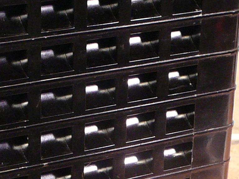
The checkered grille has many curved interior edges that retain
dirt. I cleaned them out with patience and a handful of pointed wooden toothpicks.

After cleaning, I applied wax and polished inside all of the little grille
spaces with Q-tip cotton swabs.
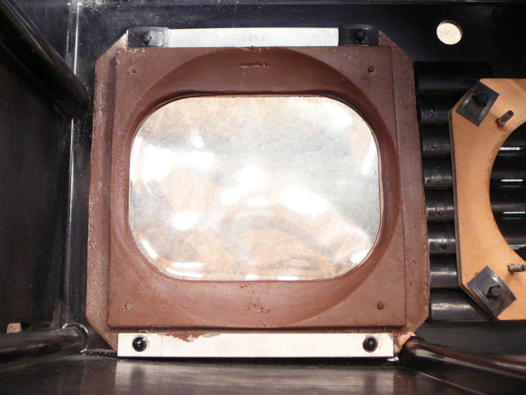
The Lucite safety cover naturally picks up scratches over the years:

The cover must be cleaned inside and out. This view shows it from
inside, encircled by the soft rubber CRT gasket:

Novus #2 makes a big improvement:

On the Home Stretch
Now, it's time for final touches, an important phase of restoration.
Once a TV basically works, it's tempting to stick it in the cabinet and
move on to the next project, but attention to detail makes the difference
between a so-so result and a restoration that you can be proud of.
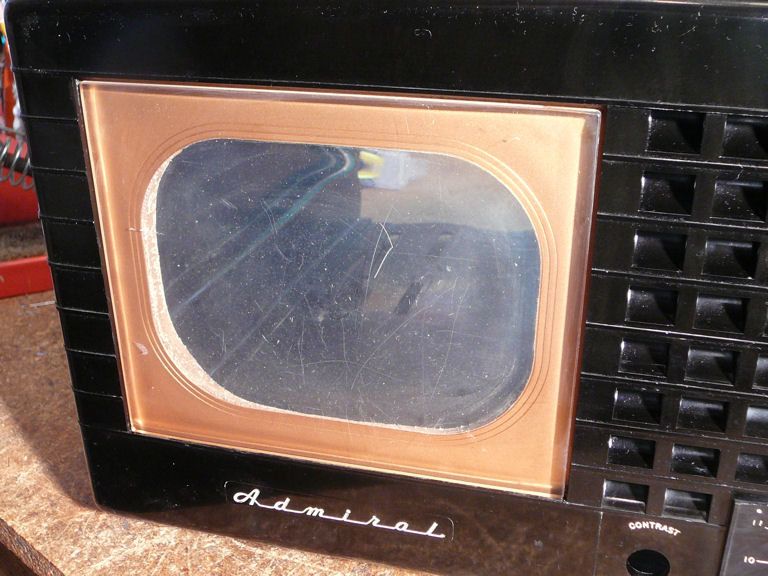
CRT Position
When placing the chassis in the cabinet,
I had noticed that the face of the picture tube was too far back.
It didn't reach the rubber gasket inside the cabinet and this created
a dark gap around the screen, which is visible in this earlier photo:
Whoever serviced this TV in the past either
didn't know how to position the tube, or didn't get far enough in the
project to care whether the screen looked normal when installed.
The Riders manual states
that the frontmost edge of the slightly bulbous CRT face must be exactly
1 15/16 inch from the chassis front panel. I moved the picture tube forward to
that point after loosening the front strap and squeezing the big clamp
on the neck.
High Voltage Adjustment
I could tell from the TV's image that its high voltage production must be
close to normal. You would not have a bright image and full horizontal deflection
if the HV were seriously lacking. It never hurts to check, however, and using my Pomona
tester I found that the HV was a little low.
I had previously replaced a number of resistors and a couple of capacitors
in the sweep and high voltage sections.
This TV's rudimentary design lacks some adjustments, such as
a drive control, that are found in more complex TVs, so component replacement is
nearly all you can do to bring things up to snuff. A couple of tricks remained,
however.
Although the 6V6 HV oscillator tube had passed as OK in my initial tube testing,
an emission check can't tell you how well a tube works as an oscillator.
The only test for that is a working oscillator circuit. Digging into
my tube stash, I found several other 6V6 tubes. Substituting each in turn,
I hand picked the 6V6 that gave the best HV output.
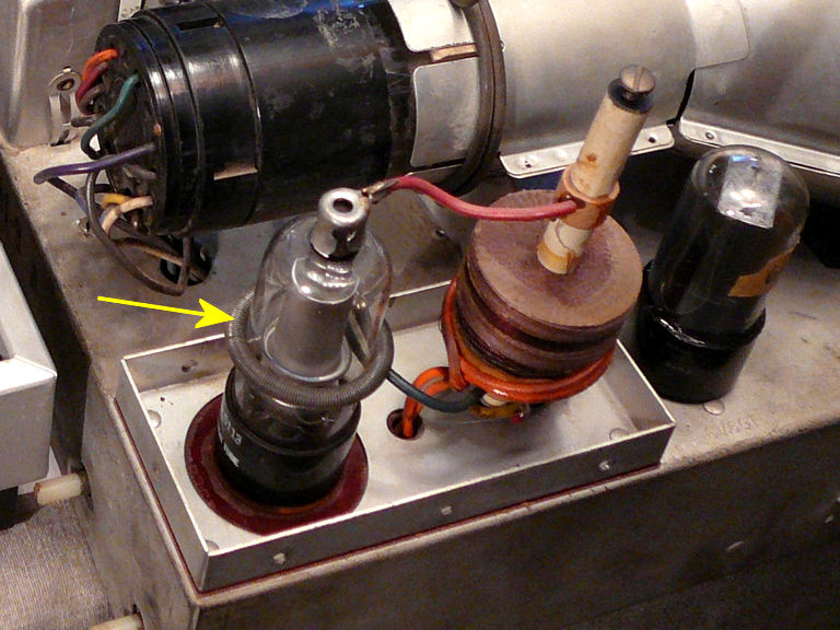
Secondly, in this type of HV supply, a capacitive feedback ring around the 1B3GT rectifier tube
can be slid up or down to optimize HV output.

When I got the TV, the feedback ring was near the waist of the tube
as shown in the photo. Moving it up and down, I found that the high voltage
output was greatest with the ring set higher, almost to the top of the tube.
Incidentally, if you've ever wondered why a TV has a metal cage over its high-voltage coil
and rectifier tube, try playing a set of this type with the cage removed (as
seen in the previous photo). The picture will develop a case of the frizzies,
responding to strong RF interference from the components normally enclosed
in the HV cage.
Improving Audio Output
The audio quality was decent, but without much volume. Turning the chassis
on its side, I carefully adjusted the ratio detector secondary as noted
in Riders and was rewarded with louder, clearer sound.
What Does the Scope Say?
Although I didn't expect anything startling, I set up my oscilloscope
and viewed a few waveforms, comparing them to the models in the Riders
manual, mainly out of curiosity. Everything looked hunky-dory, so
I set the scope aside.
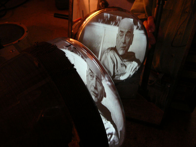
Adjusting Screen Geometry
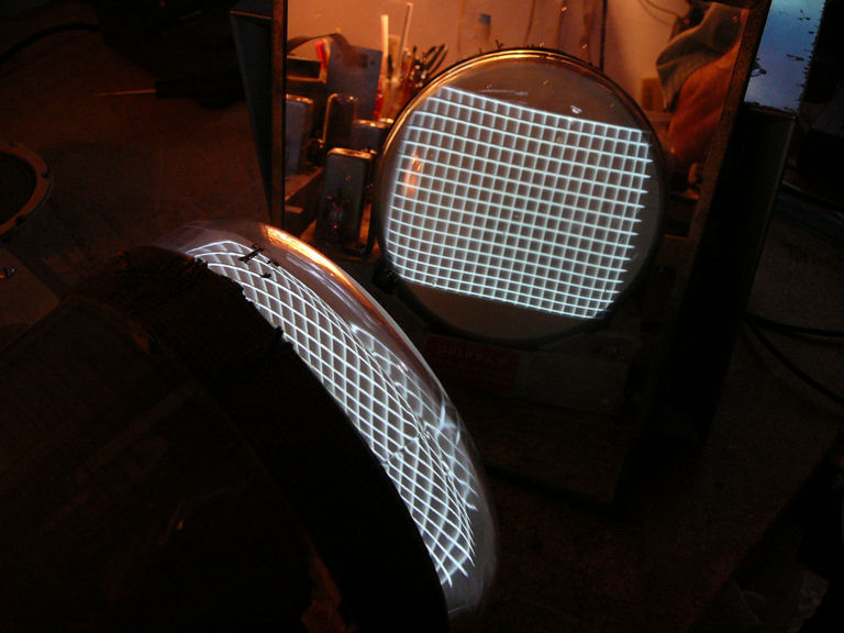
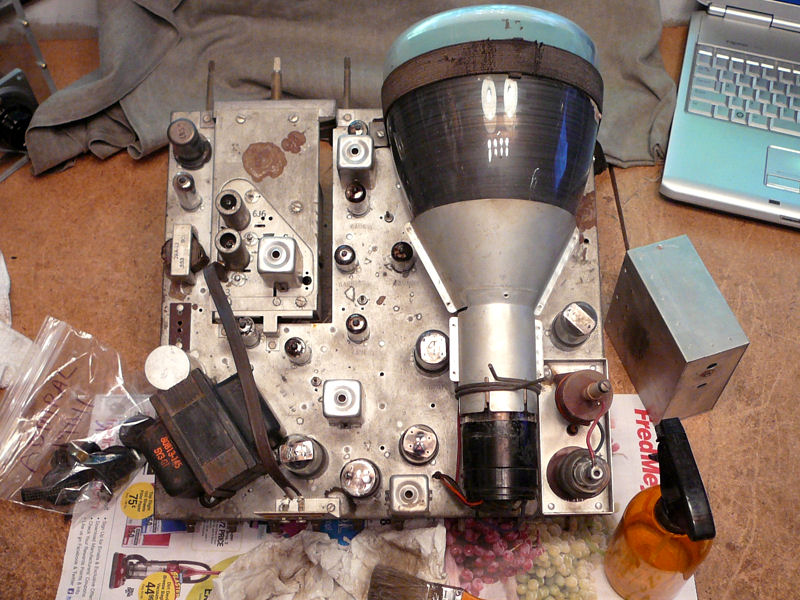
When this TV is out of the chassis, it's kinda fun to watch the image
displayed on the inside of the picture tube. Here, I'm getting
ready to make screen geometry adjustments using a serviceman's mirror.

Screen geometry includes height, width, horizontal and vertical centering,
leveling the screen, and horizontal and vertical linearity (the comparative size of objects
from left to right and top to bottom).
The second photo shows that the vertical linearity needs a little adjustment.
Squares at the bottom of the screen are slightly shorter than squares at the very top.
The crosshatch pattern in
the second photo was created by my Leader pattern generator. If you
don't have a generator, you can make a
test pattern DVD.
Shakedown Cruise
Next, I played
the TV for several hours to make sure it was stable. Here, the TV is sitting in
our family room and receiving a signal over rabbit ears from my
home TV transmitter.

It's prudent to take every restored TV on a shakedown cruise before you
wrap it up. Minor relapses are not uncommon when dozens
of old components are exposed to heat and voltage for the first time in
decades. If any backsliding occurs, it will be simpler to correct it now,
when your memory is fresh and your service manuals are at hand.
Retrace Line Blanking
After watching the TV for this amount of time, I became impatient with the
light slanting retrace lines that appeared when I turned up the brightness.
These are common in many older TVs, but I had read about a simple circuit
that significantly reduces them. It consists of a capacitor and
resistor connected between pin 5 of the vertical output tube and pin
3 of the picture tube:

When adding the circuit to this set, you unsolder the wire that connects pin 3 of
the CRT to ground and move it to the junction of the new capacitor and resistor.
I had also installed a retrace blanking circuit in my
Philco 49-1240 television,
but the Admiral's 7JP4 picture tube uses electrostatic deflection, whereas
the Philco's 12LP4 uses electromagnetic deflection. Thus, the circuit
connections and component values must differ a bit.
Cleaning the Contrast Control
At the beginning of the project, I had cleaned the easy to reach potentiometers
but I skipped the Contrast control on the front panel. It's the wirewound type,
which typically needs little or no cleaning.
After playing the TV at length, this control appeared to be a
bit scratchy, causing occasional blinks or blips in the picture. I loosened it from
the front panel, removed the case, and cleaned it with a shot of DeOxit.

On this type of TV, you will be adjusting the contrast fairly often, as you
change to different programs or sources, so you want this control to work smoothly.
While I had the DeOxit handy, I gave the tuner another light round of cleaning.
Using a Q-tip swab, I cleaned each of the dot-shaped contacts seen on
the turret in the previous photo. These had already been cleaned once, but
there's no such thing as too clean when it comes to tuners.
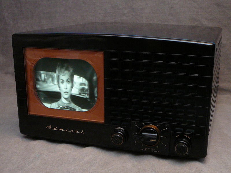
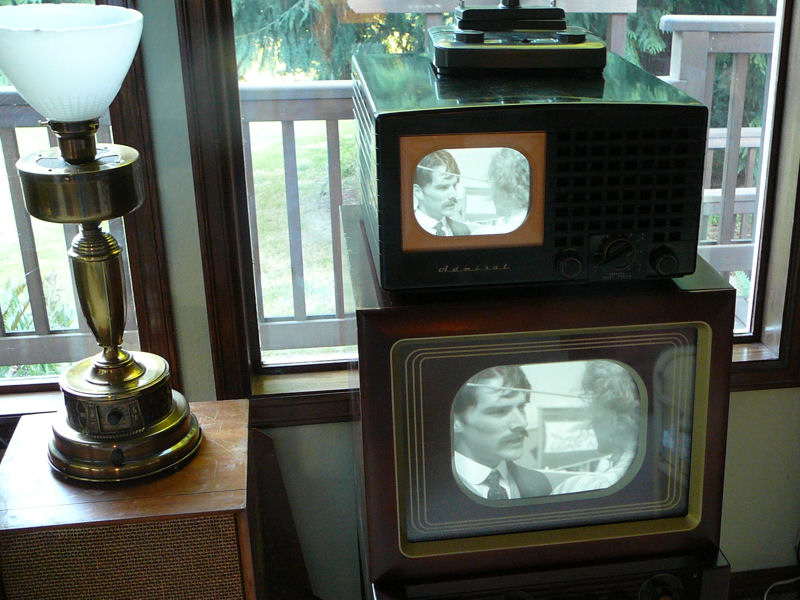
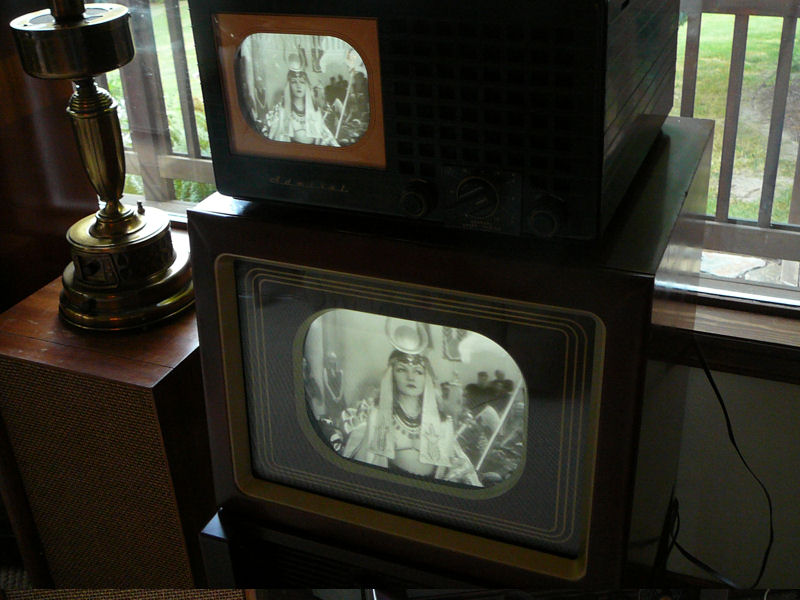
The Pepsi Challenge!
Speaking of the 49-1240, which was a recent restoration,
I was curious how the Admiral's picture would
compare, so one day I put them in the same room for a "Pepsi
challenge." As these unretouched daylight photos show, the 7-inch
picture tube looks pretty good alongside the 12-inch screen:

The TVs are receiving over the air signals from my home transmitter,
using separate rabbit ear antennas.
At last, I was ready to call the electronics complete. These photos
show the chassis before and after restoration.
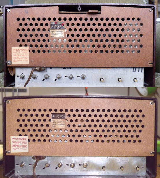
Replacing the Back Cover
The last step in this project was to replace my missing back cover. I obtained an
excellent reproduction cover from Henry Boyars. In this discussion
on the VideoKarma TV forum, he described his tools and methods, along with templates that you
can use to make your own cover.
Here is one of his reproductions, shown next to an original:

It's tricky to make clean cuts and vent holes in Masonite without furry edges, but Henry
solved the problem by careful selection of tools.
Final Thoughts
Here's a final look at my restored 19A12:
This is easily my best performing 7-inch TV, with a bright, clear
picture that's enjoyable to watch in a daylit room. Admirals were among the better performers in the late 1940s and early 1950s, and this one makes the most of a simple design.
All in all, this was one of the easiest TV restorations that I've done in years.
The set worked surprisingly well after only minimal recapping, and it only
got better as the project went along.
If you are a beginning TV mechanic, this model would be a good choice.
The design is straightforward and the construction is uncluttered,
with only a couple of busy areas around the vertical output
and horizontal oscillator tubes.
The chassis is light and easy to manage on the workbench. Unlike many
sets with larger picture tubes, the 7JP4 CRT on this set can remain mounted on the
chassis during the whole restoration. To access the circuitry underneath, you
simply lay the chassis on its side, power transformer down.
|