Pilot Model TV-37 "Candid" Television (1948)


The Pilot TV-37 "Candid" is an unusual vintage television. With a tiny
3-inch picture tube, it is barely watchable by modern standards, but the TV-37's
compact size and unusual design make it a favorite of collectors.
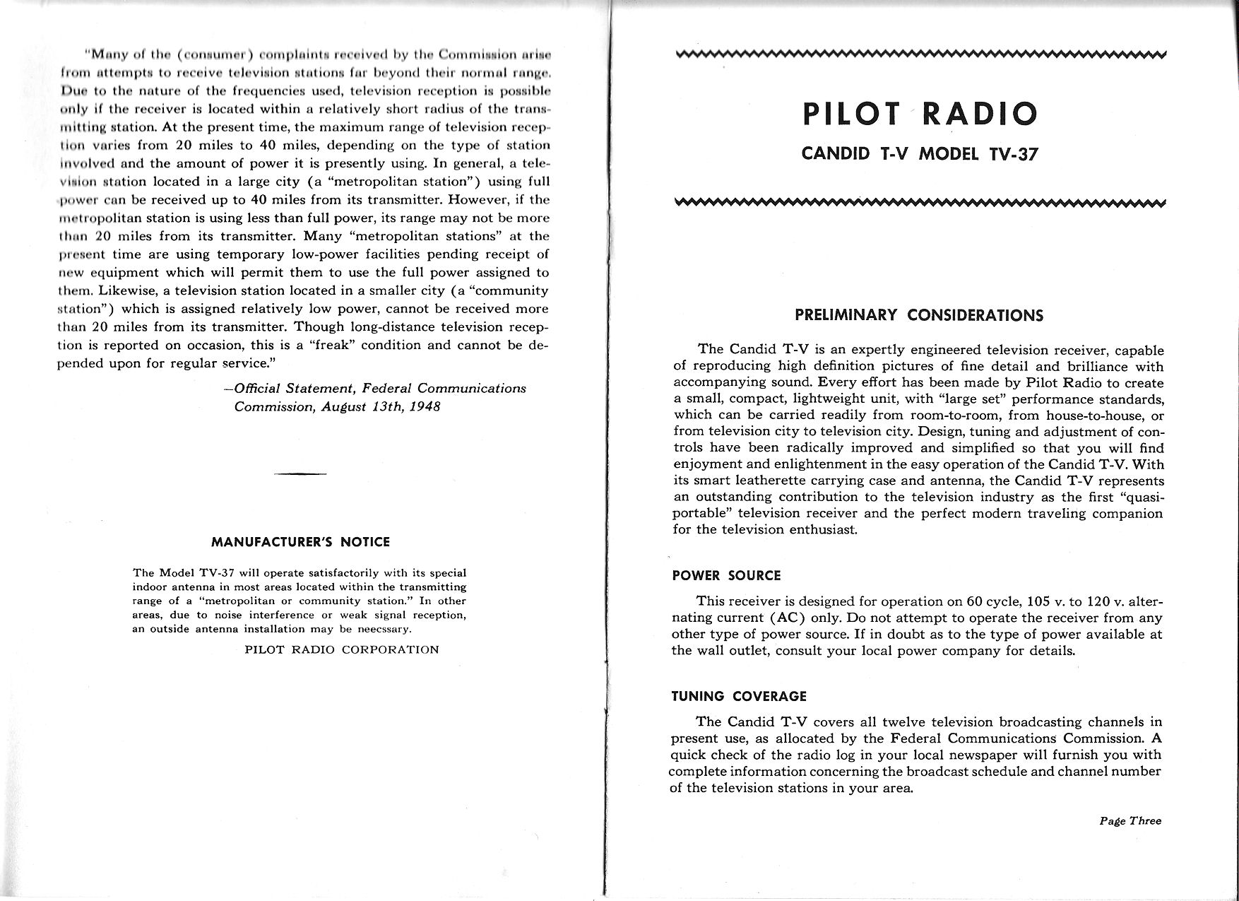
Pilot introduced the TV-37 in 1948, at the then-amazingly low price of $99. Most 1940s TVs
sold for hundreds of dollars, the cost of a decent automobile.
Pilot made this set for only a few years, but sold a lot of them during that time.
Many TV-37s still survive.
Pilot marketed this set especially to college students, and it would have been a lucky
student who got such a gift. The owner's daughter recalled neighbors crowding into their
living room in 1948 for a look at this marvelous new invention.
Description
I bought this TV-37 from the daughter of the original owner.
It had been well cared for and the owner partly restored
it during the 1960s, leaving detailed notes.
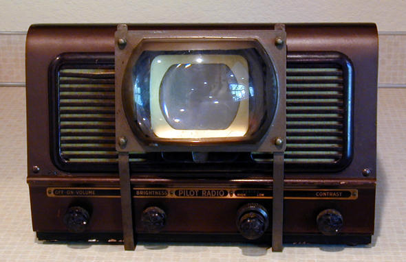
The TV is housed in a streamlined cabinet with a wooden base and an upper case
made of pressboard. The entire TV is only 14 inches wide, 13 inches deep, and
9.5 inches high, the size of a large table radio. Most of the upper case is perforated for ventilation.
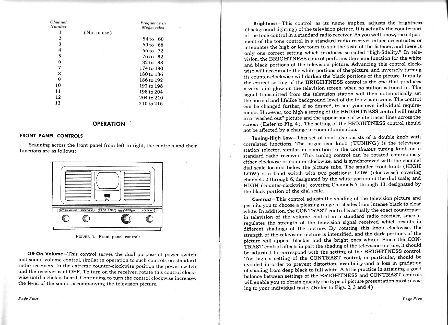
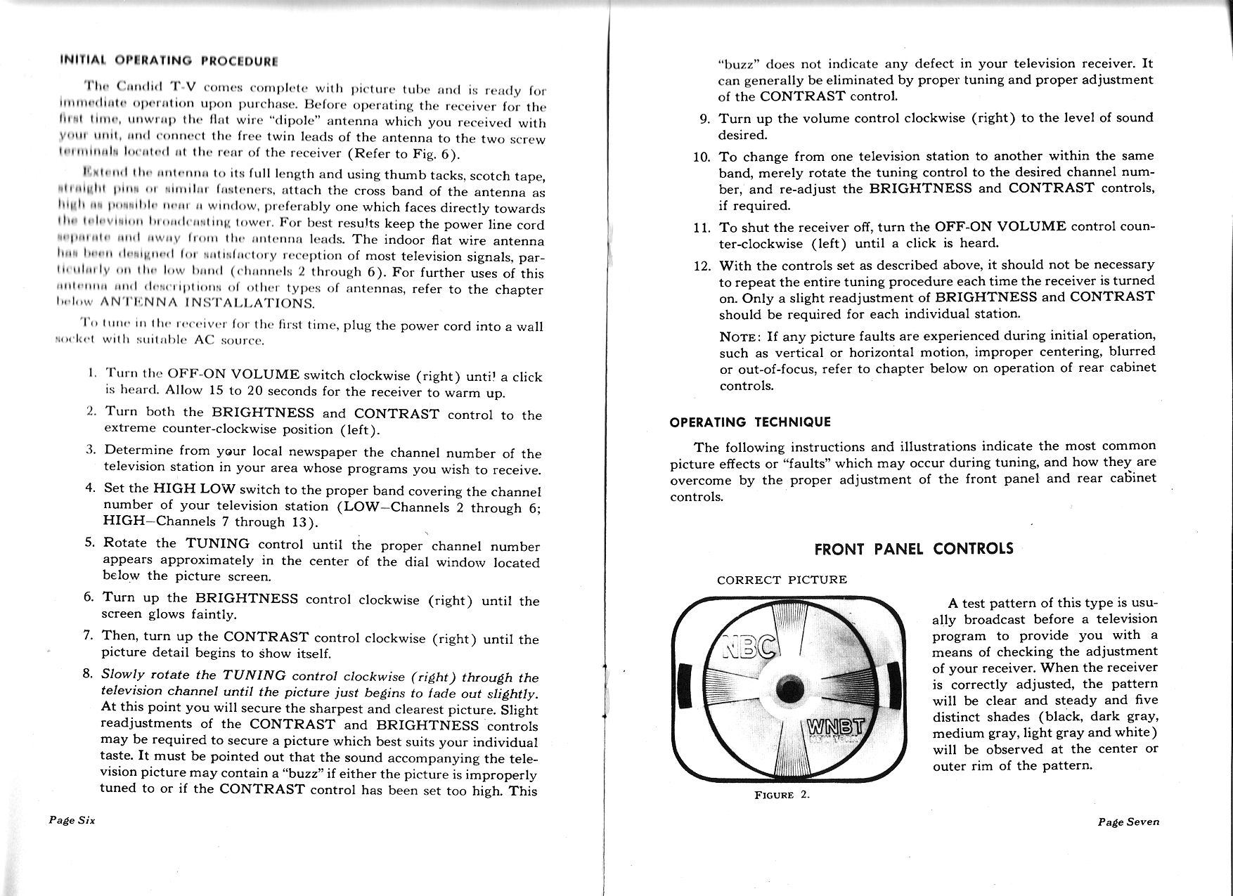
The front controls are simple: power/volume, brightness, tuning, and contrast.
The tuner control includes a high/low switch, which lets you select two tuning ranges.
The low range is channels 2-6 and the high range is channels 7-13.
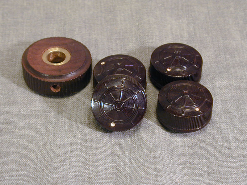
The knobs have Pilot's classic ship's wheel design. If your TV-37 is missing a knob
or two, reproductions are available.

My TV-37 came with the original owner's manual:
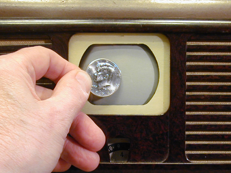
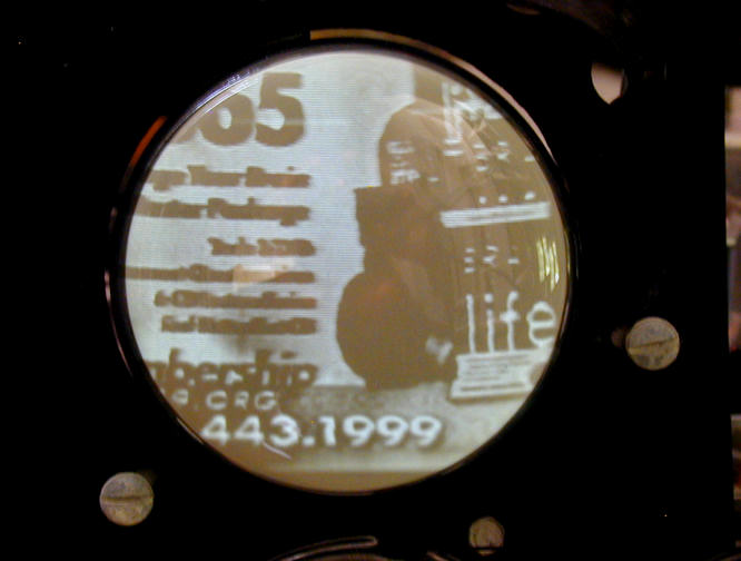
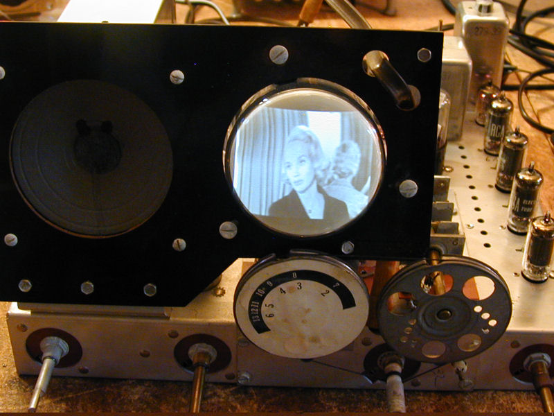
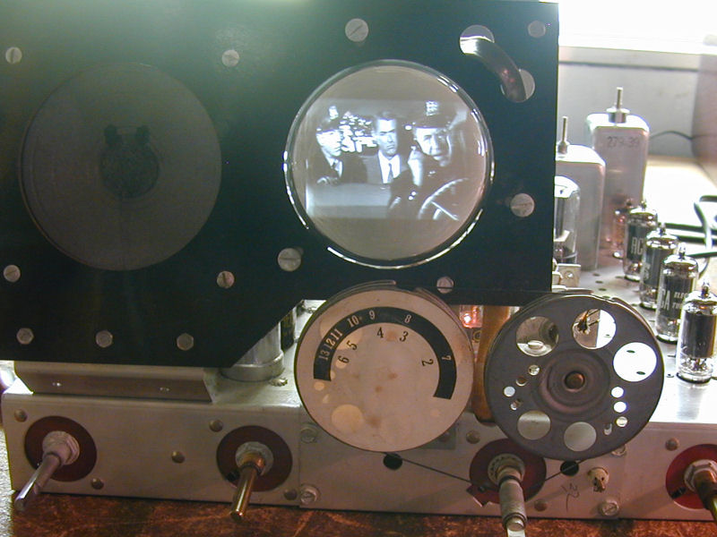
The next photo gives you an idea of the screen size. That's a half
dollar coin!

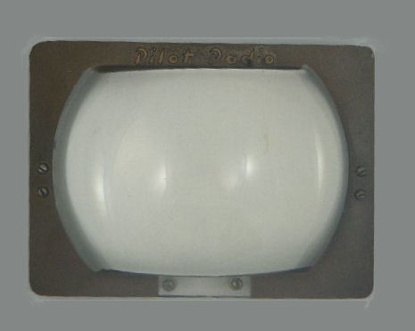
My Pilot came with a magnifying lens to place in front of the picture tube.
The second photo is animated to demonstrate the magnifier's effect.

Magnifiers were an extra-cost accessory, as was a pressboard carrying case with built-in
antenna. Magnifiers are harder to find the TVs themselves, since not everyone bought one
and some were lost over the years.
Magnifiers typically hooked onto the horizontal grill bars; these photos
show that sort of lens.


My magnifier stands on little metal legs that slip under the cabinet. The owner's notes include a pencil
mechanical drawing with dimensions for the magnifier and legs. Evidently, he built
the legs and painted them to match the trim on the magnifier.
This is an improvement over the original scheme, since the heavy
magnifier tended to warp or break the thin grill bars.
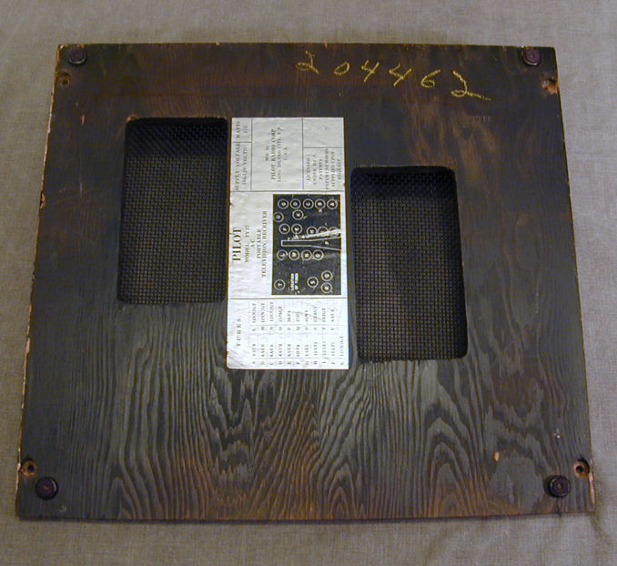
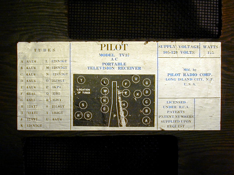
On the bottom of the wooden base is a label showing the tube layout.
The TV's serial number (204462) is written there in yellow crayon and
also stamped in the rear of the aluminum chassis.


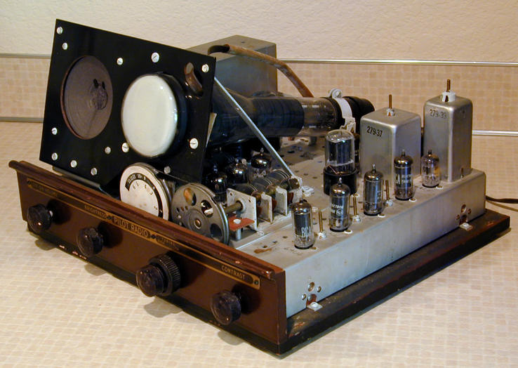
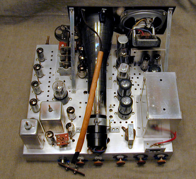
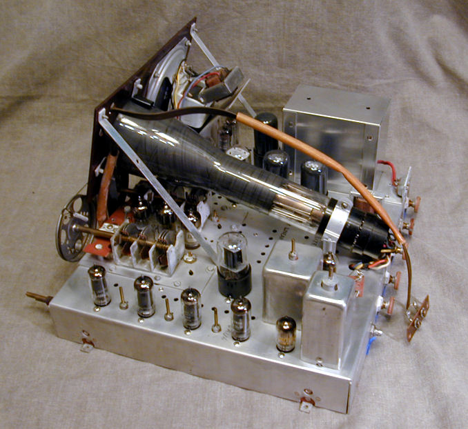
The next photo shows the TV-37 with its hat off:
The TV-37's electronic design is similar to other electrostatic-deflection TVs
of that era, such as my 7-inchers, the
Admiral 19A12,
National TV-7W,
Motorola VT-73, and Hallicrafters 505.
The television uses 21 tubes, including a 3-inch electrostatic-deflection
picture tube.
| Tube |
Type |
Function |
| V1 |
12AT7 |
RF amplifier |
| V2 |
12AT7 |
Mixer |
| V3 |
12AT7 |
Oscillator |
| V4 |
6AU6 |
1st IF amplifier |
| V5 |
6AU6 |
2nd IF amplifier |
| V6 |
6AU6 |
3rd IF amplifier |
| V7 |
6AU6 |
4th IF amplifier |
| V8 |
6AU6 |
Video amplifier |
| V9 |
6AU6 |
DC rest./Sync. separator |
| V10 |
6AU6 |
Sound IF amplifier |
| V11 |
6AL5 |
Ratio detector |
| V12 |
35B5 |
Audio amplifier |
| V13 |
12SN7GT |
Vertical multiplier |
| V14 |
12SN7GT |
Vertical amplifier |
| V15 |
12SN7GT |
Horizontal multiplier |
| V16 |
12SN7GT |
Horizontal amplifier |
| V17 |
25L6GT |
High voltage oscillator |
| V18 |
1B3GT |
High voltage rectifier |
| V19 |
35W4 |
Negative rectifier |
| V20 |
25Z6GT |
Positive rectifier |
| V21 |
3KP4 |
Picture tube |
The TV-37 has DC restoration but it lacks AGC (automatic gain control). Its
Contrast control could more properly called a manual gain control, since
it varies the gain of the RF and IF amplifiers. As with other TVs using
manual gain control, such as my
RCA 630TS, you'll need to adjust this
when switching from one source to another (or sometimes, from one
program to another).
Unlike most TV tuners, the Pilot's is continuously variable. Instead of clicking
from one station to the next, it turns smoothly like a radio tuner. This
was a cost-saving measure; the Pilot tuner contains far fewer parts than other
TV tuners. Its construction is similar to a radio tuner, using air variable
capacitors, pulleys and strings. (Don't confuse this type of
tuner with the robust—and vastly more expensive—continuous tuners used
in my DuMont RA-103 and
RA-113 televisions).
Another cost-saving (and weight-saving) design tactic was to eliminate the
expensive and heavy power transformer. This is a transformerless "series string"
TV, in which the tube filaments are connected in series. As in series-string radios, the
voltages of the tubes add up to the voltage of the AC power supply (around
120 volts). Given the number of tubes, it actually uses two parallel tube
strings, a design repeated in some other TVs such as my Philco Predicta.
Here are the Riders and Sams service manuals for the TV-37.
To download one to your computer, right-click on the icon and then choose Save Target As.
Pilot produced early (TV-37) and late (TV-37U) versions of this television, with some electronic
changes as well as slight cosmetic differences. In this
forum discussion you'll find
a summary of the changes.
The 3KP4 Picture Tube
As far as I know, the Pilot was the only consumer television to use the three-inch
3KP4 picture tube.
Even early kit TVs of the 1940s used larger tubes.
The Pilot's 3KP4 is also notorious for burning out because it
(along with the other tubes) is subjected to a stiff power surge when you
turn the set on. As a result, 3KP4s are scarce and costly.
One cure for the surge problem is to disconnect the picture tube's
filament from the filament string and supply it independently from
a small 6.3-volt transformer (the Triad F-13X is suitable).
When this is done, you should also install a 12 ohm power resistor
at the picture tube's former position in the filament string.
Another remedy is to install a type CL-90 thermistor on the AC line
between the power switch and the filament string. The thermistor
presents a higher resistance when cold, which decreases to almost
nothing after it warms up. The "soft start" moderates the
surge. Thermistors were a standard feature in my Philco
Predicta and other later TVs.
Some Pilot owners substitute the more common 3KP1 picture tube if their original
3KP4 is burned out, or simply for testing purposes during restoration.
The 3KP1 is electrically interchangeable but it was designed
for 1940s oscilloscopes with green screens.
The 3KP1 is not an ideal substitute. A green phosphor tube is
darker than a white one, making normal viewing a challenge. The slow-response
green phosphor also creates trails on fast-moving objects.
Since a 3KP4 cannot be tested on any tube tester, I couldn't tell at first
whether mine was good.
I tested the filament with an ohmmeter and found that it had continuity, so
I knew it wasn't a total dud, at least. It still might have poor emission and
thus be too dim to watch, however. Only restoring the TV will
tell me whether it really works.
Restoration
The cabinet required no cosmetic restoration except for touching up
a couple of tiny paint nicks on the base. Like all TVs of this vintage,
the chassis will need electronic restoration to be made reliable.
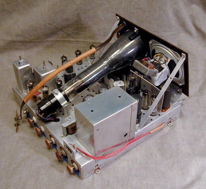
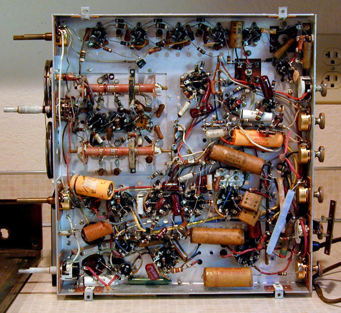
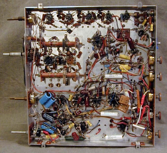
This photo shows the underside of the chassis as found:
The previous owner had done some restoration, replacing about ten paper
capacitors and a few resistors. I'd guess the work was done in the 1960s, judging
by the type of components used and the fact that the owner retired in 1965.
Most of the replacements were epoxy-dipped caps, usually far more reliable than paper, so
I decided to leave them in place until I replaced the others
and judged how the TV works.
The chassis still contained all of the original electrolytics, plus
about a dozen paper capacitors, including the critical high-voltage caps.
Those will be replaced by me.
Before replacing anything, I tested all of the tubes and cleaned their pins.
I also cleaned and lubricated the tuner and all
of the control potentiometers (volume, brightness, etc.). The tuner and two potentiometers
were completely stuck on their shafts, but I freed them with solvent
followed by electronic cleaner and lubricant.
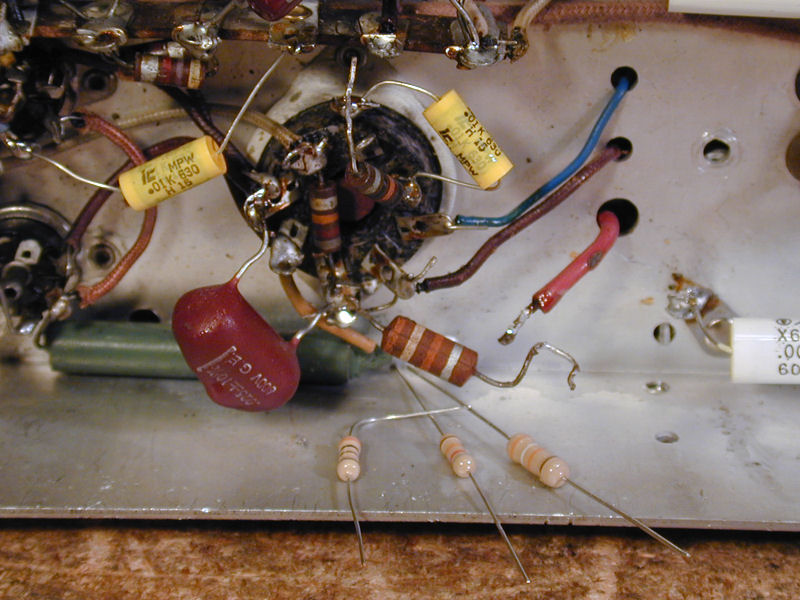
Capacitors, Capacitors
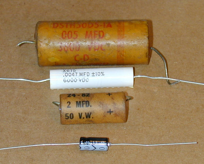
After receiving some new parts in the mail, I began
replacing capacitors.
The new ones are smaller than the originals, making it easier
to fit them into tight spaces.

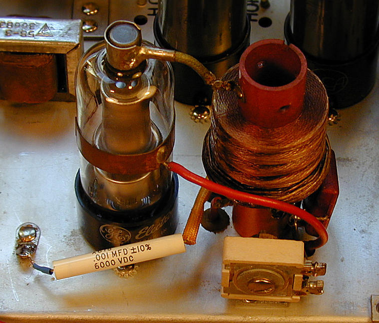
Notice the tubular film capacitor rated for 6000 volts. I prefer to replace
high voltage caps with this type rather than ceramic discs, which may be
unstable. You can get tubular HV-rated caps from
Just Radios.
I replaced all of the electrolytic capacitors, including a couple
that looked like 1960s replacements. On some TV-37s, capacitor C2
was mounted underneath the chassis. On mine, it was mounted in a
can atop the chassis. There's plenty of room underneath, so I
mounted the replacements down there and left the old
cans in place for appearance.
Note that two of the power-supply electrolytics, C2 and C3, are
installed with their positive leads connected to the chassis ground.
This is different than what you'll see in many radios and TVs.
Don't install those two backwards—your TV won't work!
Don't forget the capacitor inside the high voltage cage.
Pay attention to the little copper collar on the midsection of the 1B3GT tube.
It is important for correct high voltage output. Before removing the tube for
testing, I marked its position with a Sharpie and took care to slide it back
into the right place. You can read about the purpose of this connection
in my Motorola VT-71 article.
First Power-Up
With new electrolytics and high-voltage caps, it was time to try
firing up this TV. I connected it to a variac and slowly brought
up the voltage, looking and listening for any signs of trouble.
The tube filaments began to glow, but there was no sign of
a raster on the CRT. I could hear a putt-putt sound from
the speaker, which became faster as I increased the voltage, but
no real audio.
Time for some voltage checks! I quickly determined that the B+ voltage
was much lower than specified in the schematic.
I re-tested the two rectifier tubes (25Z6GT and 35W4) and re-cleaned
their pins and sockets, just in case of a bad connection. The B+ voltage
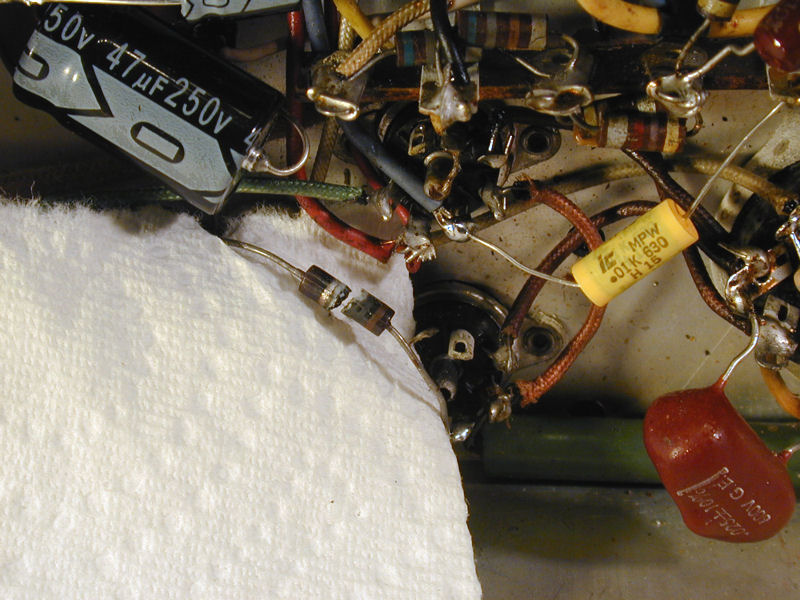
was still too low. Acting on a tip from a fellow TV-37 owner, I connected
a modern silicon diode across the 25Z6 tube, between pins 3/5 and 4/8,
with the positive band of the diode pointing to the positive lead of
electrolytic C1A.
That brought the B+ voltage up to a normal level. On the next power-up, I
was delighted to hear excellent audio from the TV on its upper channel range,
indicating that the TV's tuner and audio sections were basically functional.
Not so good on the lower channel range, but we could defer that investigation
until later.
High Voltage Testing
The absence of a raster suggested that we still had problems in the
high-voltage power supply—often the trickiest section to restore
in any vintage TV.
The data sheet
for the 3KP4 picture tube indicates that you need a minimum of 1000 volts
and a maximum of 2500 volts.
You can't test high voltage with an ordinary multimeter. I have two probes
suitable for this. The one on the bottom of the photo is my favorite,
a Pomona 2900A. It operates all on its own. The probe on the top is
an RCA WG-284, which can be used with my old RCA Senior Volt-Ohmyst tester.

Testing indicated only about 800 volts, where you would expect to measure
at least 1 kilovolt. That explains the lack of a picture!
Resistors, Resistors
The high voltage section of an electrostatic-deflection TV typically
contains several resistors with values over 1 megohm, and the Pilot is no exception,
using values as high as 4.7 megohms.
Old carbon composition resistors often drift upward, and several
of this television's high-value resistors had drifted badly, sometimes to as much as
twice their original value. I replaced several of the worst offenders, but
the high-voltage level was still deficient.
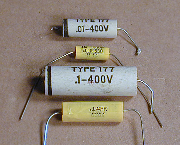
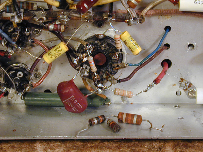
A Light Bulb Goes Off
Then I remembered that a few of the 1960s replacement capacitors were not
"maroon drops." Three of them were white, apparently cased in
ceramic, and the fourth was a large yellow Mallory "Plascap."
I hadn't run across either type before, but I dimly remembered something
about ceramic tubular caps being paper capacitors in disguise—and
potentially as troublesome. I sent a brief query to a vintage TV forum
and got a consensus that both types should be replaced.
Here are some of the 1960s culprits and their modern
replacements.

First Picture!
After replacing those caps, the next power-up gave the first pictures I had seen
from this television!

Now, this picture isn't perfect, but it's always exciting
to see an old baby like this come back to life. Best news of all, the image indicated
that my rare CRT was not a total dud.
The picture was very dim, visible only in a dark room, and the width and height
were excessive. When the TV is inside the cabinet, the image size will need to
be reduced to fit inside the mask.
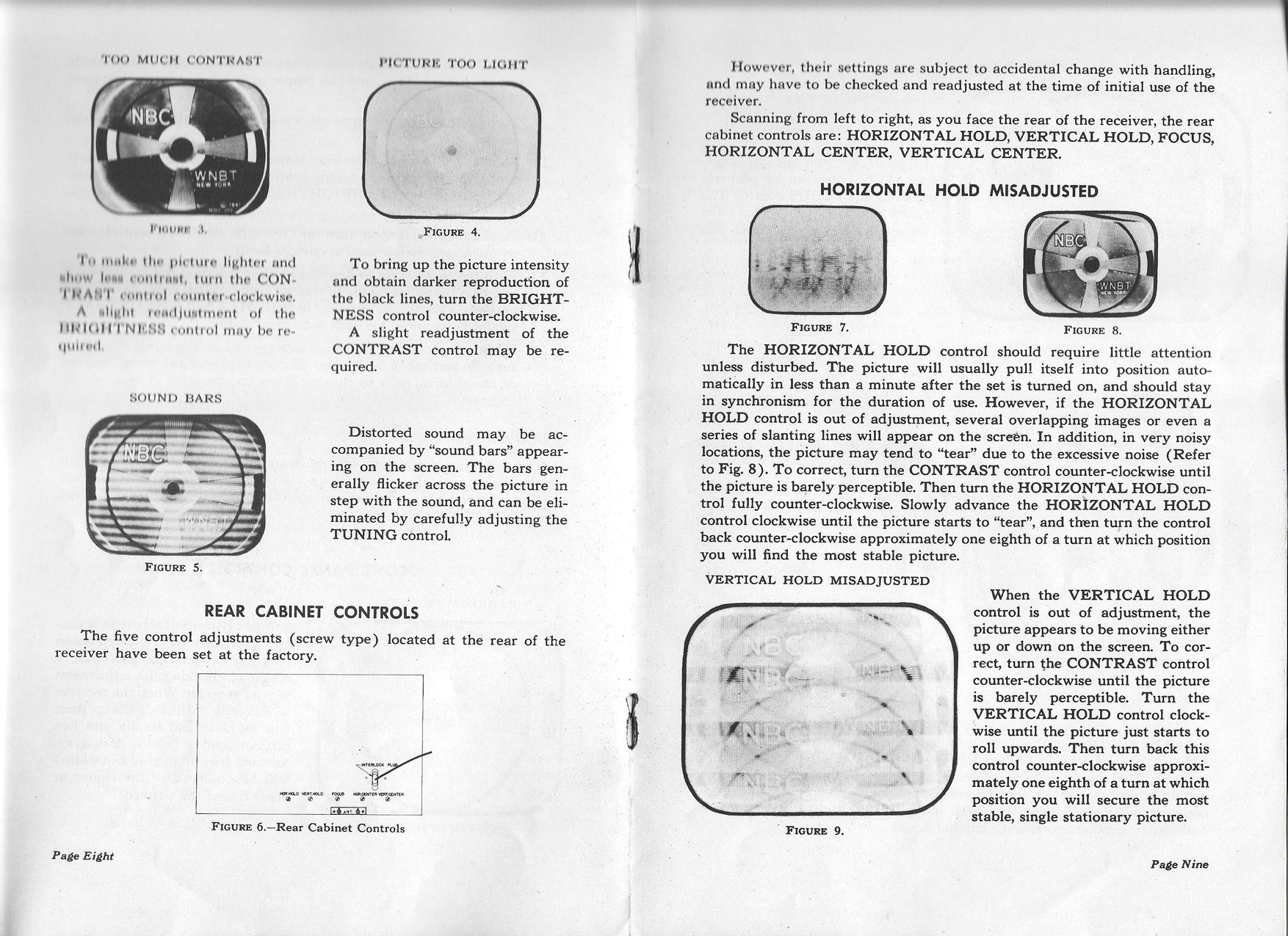
The excessive height accentuated the horizontal scan lines, and the
vertical and horizontal centering were also a bit off, but these are all things
that you can adjust by twiddling controls.
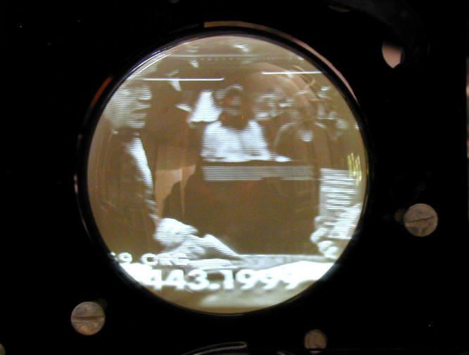
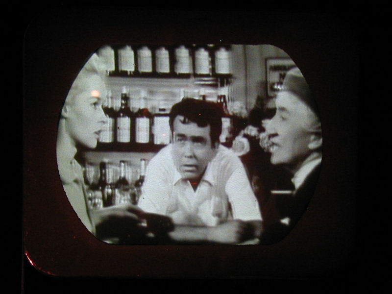
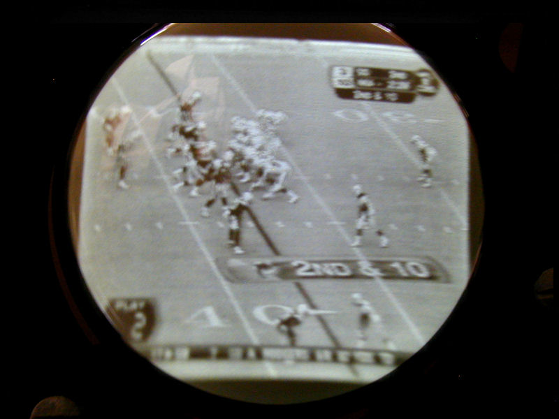
These are photos of live broadcasts, received with a 1950s rabbit ear antenna.
We live in an area where all broadcast signals are pretty
weak, so this was an encouraging sign, showing that the TV
has decent sensitivity. (2012 note: this part of the restoration
was done before the 2009 changeover from analog to digital TV broadcasts.)
Another photo shows fair detail, so the
tuner and IF sections are passing a reasonably clean signal.
You can read "2nd & 10" in the little scoreboard near the upper right:

(The actual picture is sharper than in the photo; my camera has trouble
focusing on CRTs.)
If you view the previous photo on a normal size computer screen, it's
roughly double the size of the TV-37's picture. Okay, so the Pilot's
not ideal for watching sports events, but other kinds of programming
can still be fun to view.
Restoration, Round Two
That's where the restoration remained for a few years. I got distracted by
new projects and the poor little Pilot languished on a shelf.
In 2012, I brought the TV-37 back into my workshop to complete the job.
Although I had coaxed a picture out of it before, the
image was dreadfully dim and I hadn't really finished the restoration.
The first trial was discouraging, with no hint of a screen image, although
the audio was still working. A quick check revealed that high
voltage was completely absent.
Here's an obvious troublemaker. This resistor tested open on my ohmmeter,
and when I grasped one end with a pliers to unsolder it, the two halves
fell apart.
Replacing that resistor brought a faint glimmer to the screen, but
the high voltage was still too low and no video signal was apparent.
I began methodically checking resistors, starting with those in the horizontal
and high voltage circuits. Many were far off tolerance,
and so out they went. These photos show the replacement of three
resistors on the 26L6GT horizontal oscillator tube.


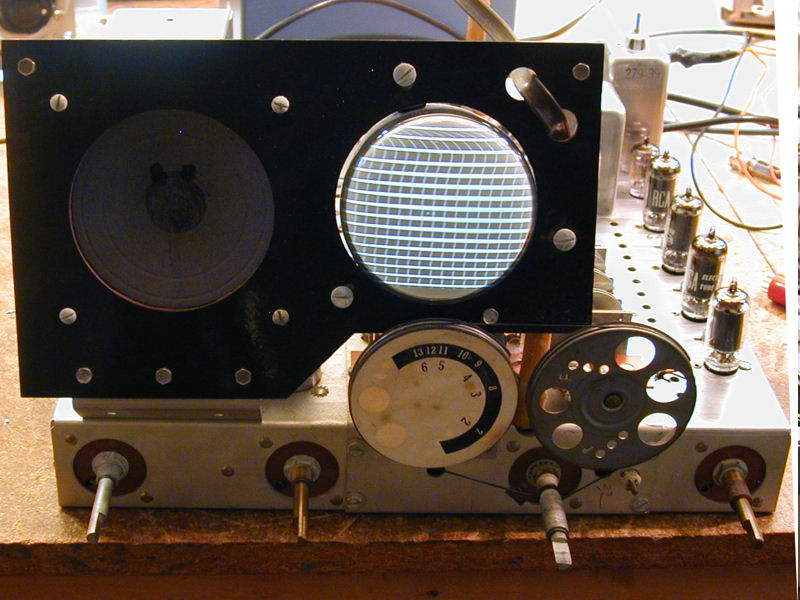
Tedious work, but soon I could get a coherent image on the screen again.
The next photo shows a crosshatch test pattern. The picture was rather
unstable, however, with poor brightness and contrast.

Although the screen looks fairly bright in the previous photo, that
shot was taken in a dimly lit room with faint backlighting. The
camera's auto-correction made everything, including the screen
pattern, brighter than in life.
Working through the high voltage, sweep, and video sections,
I found more and more bad resistors. As I replaced them, the picture gradually stabilized
and improved in brightness and contrast. Here are some photos taken during the process.


In the first photo, the brightness has improved but the contrast is deficient,
leaving the image flat and lifeless. By the time we get to the third photo,
we have a fuller dynamic range.
Final Thoughts
I put the chassis back into the cabinet and made the final adjustments for
screen height, width, and so on. Then I bench tested the TV for a few hours.
It performed well and looked stable, so with that, I declared victory.
On to the next project!
Here's the restored TV-37 from all angles:


To celebrate my Pilot's return to the living, let's take another look at
the animated .GIF showing it with and without the magnifier:
I didn't install a filament transformer or thermistor in this TV, after all. It won't get
played often, so I'll just give it a slow power-up on the variac when I
show it to visitors.
|

