Motorola VT-73 (VT-71) "Golden View" TV (1948)


Motorola's "Golden View" was the most popular 7-inch television in the late
1940s and early 1950s. It came in both tabletop and portable cabinets and it was one
of the cheapest TVs available at the time. Motorola must have sold a boatload of
these TVs, because they are still quite plentiful in the collector market, often
priced under $100 for a set in decent condition.
Description
Like my 1948 Hallicrafters 505
and National TV-7W, this TV used a
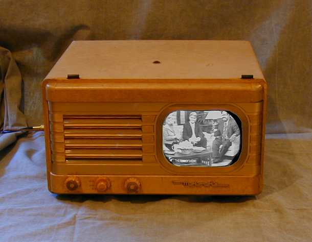
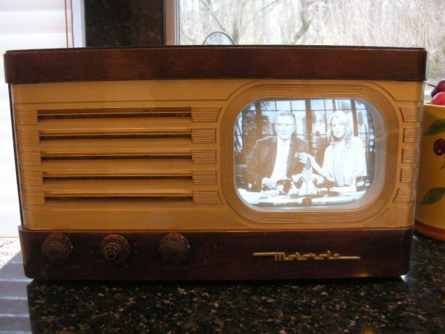
7-inch electrostatic deflection picture tube. The following photo shows the restored TV.
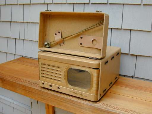
My set is a model VT-73, which came in a portable, leatherette-covered case. The next photo
shows the cabinet with chassis removed. The hinged cover was used to stow a rabbit-ear antenna.
Wooden tabletop cabinets were also available. Other models in this series
include the VT-71 and VT-72.
This is a sixteen-tube television. The tube lineup follows.
| Tube |
Type |
Function |
| V1 |
6AG5 |
RF amplifier |
| V2 |
12AT7 |
Converter |
| V3 |
6AG5 |
1st video IF amp |
| V4 |
6AG5 |
2nd video IF amp |
| V5 |
6AG5 |
3rd video IF amp |
| V6 |
6AU6 |
Video amplifier |
| V7 |
6AU6 |
Sound IF |
| V8 |
6AL5 |
Ratio detector |
| V9 |
12SN7GT |
AF amp./Vert. oscillator |
| V10 |
25L6GT |
Audio output |
| V11 |
12SN7GT |
1st & 2nd sync. clipper |
| V12 |
6SL7GT |
Vertical amplifier |
| V13 |
12SN7GT |
Hor. AFC/Hor. osc. |
| V14 |
25L6GT |
High-voltage oscillator |
| V15 |
1B3GT |
High-voltage rectifier |
| V16 |
7JP4 |
Picture tube |
It's interesting to compare this design to the Hallicrafters
505, which was similar electronically but used twenty-two tubes rather
than sixteen. The Motorola design used two selenium rectifiers
in the low-voltage power supply, whereas Hallicrafters used two rectifier tubes.
It also employed a single dual-function tube in places where the
Hallicrafters set used two separate tubes. For instance, one
12SN7GT tube acted as the AF amplifier and the vertical oscillator,
jobs that were done by two tubes in the Hallicrafters set.
The Motorola VT-73 also has a much simpler tuning mechanism. In the
Hallicrafters 505 (and T-67 for that matter),
tuning of channels 1-13 is accomplished through a bank of thirteen
pusbutton switches. The Motorola tunes channels 2-13 with a simpler,
and cheaper, rotary switch.
Unlike more modern TV tuners, the Motorola's can select only eight stations.
As noted in the service literature, the FCC limited
the number of TV stations in any given locality to eight. Thus, the
TV would be set up by the dealer to tune up to eight local stations
in the area where it was sold.
To allow for tuning all thirteen channels with only eight positions, some
switch positions can be preset to one station or another. On my set, the
first position can be
set to receive either channel 2 or channel 3. The next few positions can
only be set for channels 4, 5, 6, and 7. The last few can be tuned for
either 8 or 9, either 10 or 11, and either 12 or 13.
This scheme certainly reduced the cost and complexity of the tuner,
an appropriate decision for an inexpensive television. The
drawback was that, if you moved to a different town with
a different combination of TV stations, you would have to bring the
TV to a service shop to reset the tuner. Later TV designs settled on
a more robust turret-style tuner that tuned all of the available channels.
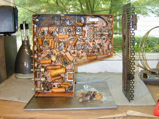
The Motorola is comparatively easy to work on. The chassis is light and
easy to handle on the workbench, and the electronics are not too crowded,
something that occasionally happens with more complex TVs or radios.
Motorola made a number of electronic changes during the life of this model series.
The Rider service literature is 91 pages long (!) and lists at least eight different chassis, TS-4B through
TS-4J. If you're going to restore one of these, make absolutely sure that
you get the correct schematic. I have two different "TS-4J" schematics,
and while one is much closer than the other, it still doesn't match exactly
what's in my chassis. You can download service literature from the Early Television
Foundation archive
Restoration
My set was in good cosmetic shape, requiring only the usual cleanup and polishing of the
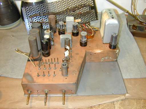
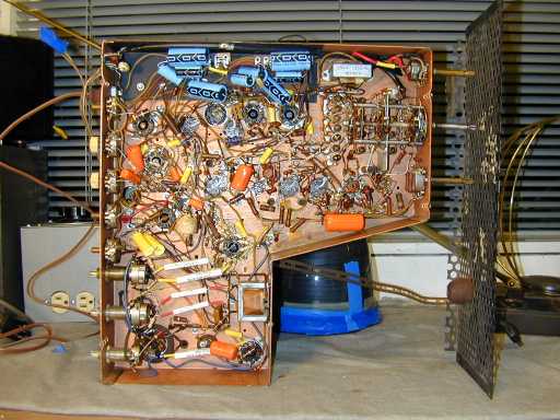
plastic faceplate. The next photo shows the chassis removed from the cabinet. A few bad
tubes have been tagged with masking tape for replacement.
This chassis is copper plated. The smudge at lower left shows where I did some test polishing.
I'm not trying to make this set look a museum piece, but if you wanted to invest the time,
you could make such a chassis look pretty impressive.
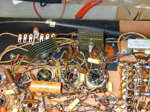
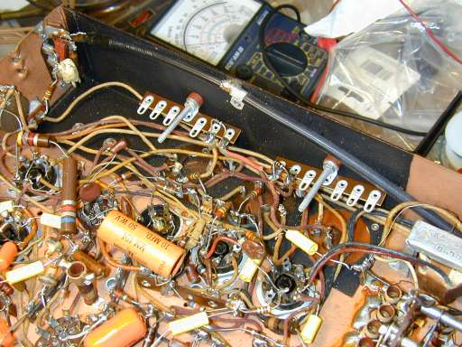
Underneath the chassis, you will find the usual assortment of old paper capacitors, along with
a pair of selenium rectifiers. All of these will need to be replaced, along with several
electrolytic capacitors, before the set can be expected to work properly. See the article
Replacing Capacitors in Old Radios for details on those procedures.
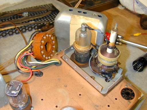
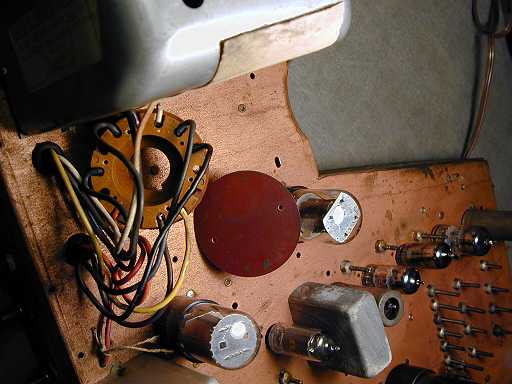
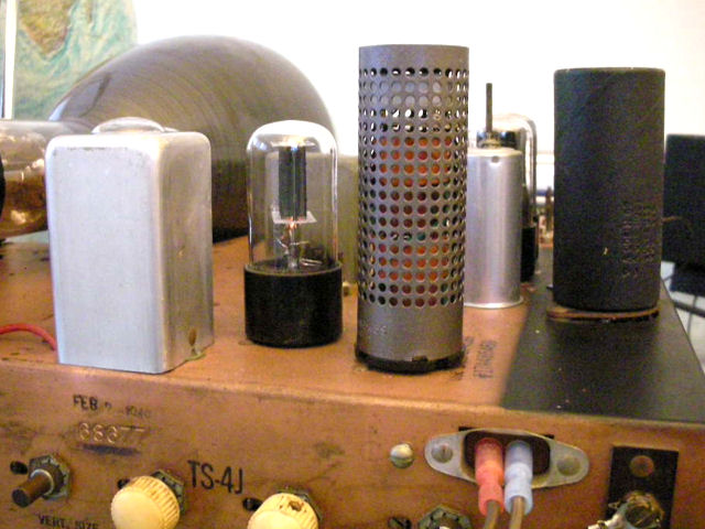
Inside the high-voltage cage is a transformer and the type 1B3GT high-voltage rectifier tube.
Notice the thin copper coil spring mounted midway up the tube body. This spring provides feedback to the oscillator
grid through capacitive coupling and its positioning is critical for correct operation. The service manual indicates that it
must be positioned 3/4 inch above the top of the Bakelite tube base for the 1B3GT tube, or 13/12 inch
above the base for the older 8016 tube. On the original tubes, like the one shown, a piece of tape
was wrapped around the tube and marked for the correct position. Then the spring was cemented
in place. If you remove your rectifier tube, be sure to get the spring back in the right position.
Replacing the Ballast
Another critical component in the TV's power supply is the ballast. Often called a "tube,"
the ballast is simply an array of high-wattage resistors mounted inside a ventilated metal
case and using a conventional 8-pin tube socket.
Old ballasts are failure-prone and frequently need replacement. Sometimes you can find NOS (new
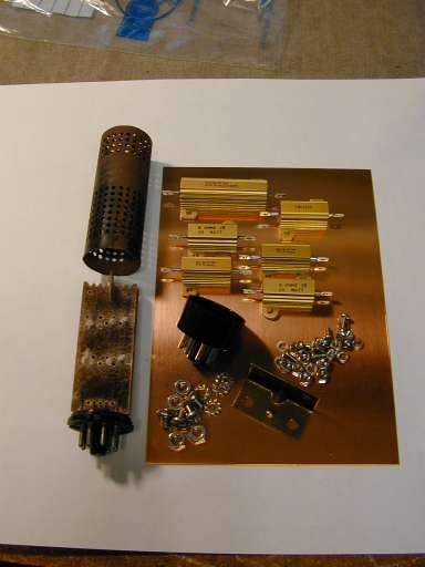
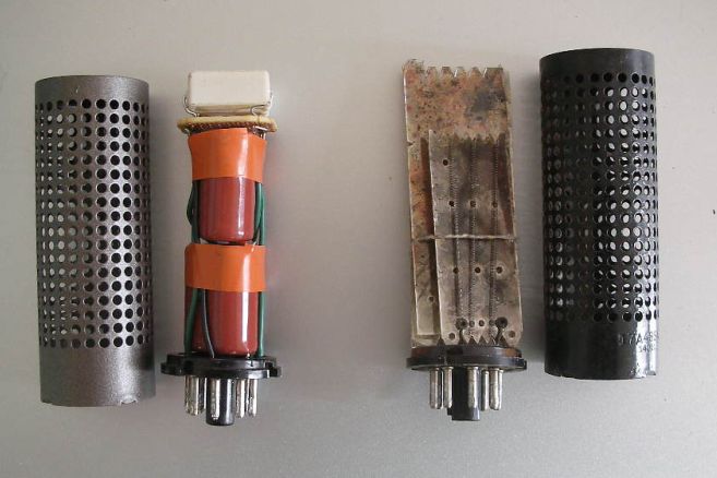
old stock) ballasts from a used parts supplier, but you can also build a new one. The next photo shows
the old ballast and the modern parts I used to replace it.
On the left of the photo, you can see the crusty old metal cage and its innards.
Ballasts
were made by stringing high-resistance wire on flat mica pieces. They failed when one or more
of the wires burned out from use. I made the replacement by mounting modern Dale-type power
resistors (all 25-watt rated) on a small copper sheet and connecting the resistors to the
pins of a new tube base.
Motorola used at least two different types of ballast for this TV, so check your schematic
carefully before building a replacement. My ballast contained four resistors, but some
sets used a five-resistor ballast.
Like many inexpensive radios of the time, this TV has an "AC/DC" type power supply with no power transformer.
In such a supply, the filaments of the tubes are connected in series to the 120-volt AC power line.
For classic
AC/DC radios, the designers chose five tubes whose filaments added up to about 120 volts. Since a TV has many more
tubes—sixteen in this case—the designer would split the filament strings in two and wire them up
in parallel. This resulted in somewhat less than the desired resistance for each string, so the ballast resistors
were used to make up the difference.
The replacement was not difficult to make. The copper sheet was purchased for about $3 at a craft store.
I used a small razor saw to cut the plate to size, 3 inches by 5 inches. If you're going to mount the replacement
on top of the chassis, as I did, don't make it taller than 5 inches or your chassis won't fit inside the cabinet.
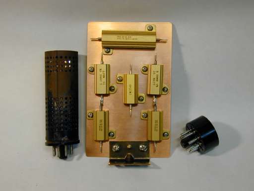
The next photo shows the resistors and bracket mounted on the plate.
The resistors need to be high-wattage because they are wired in series with the AC line.
The copper plate helps to dissipate their heat.
My ballast required two 105-ohm resistors. I couldn't get resistors of that value, so I wired
100-ohm and 5-ohm resistors in series to make up those components. The cost of the resistors
was about $35 and you can order them from
Allied Electronics.
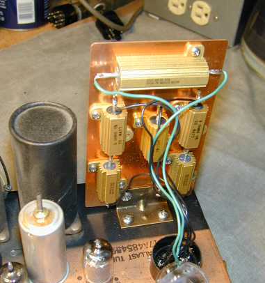
Here is the working ballast replacement mounted on the chassis and plugged into the socket.
In the area where I mounted it, there are no major components located on the underside
of the chassis. All that you need to do is hold cables out of the way while you drill
the mounting holes. Don't try to mount a replacement under the chassis.
These big resistors generate a lot of heat! That's why the designers used
a ventilated above-chassis ballast in the first place.
At the time these photos were taken, I had not gotten around
the insulating the exposed leads on the resistors. Insulation is important because some of the
connections carry high voltage.
Building a Better Ballast
Several years after I wrote this original article, a fellow collector
devised a clever ballast circuit using capacitors. The substitute ballast creates
less heat than the original and even fits in the same housing.
The circuit was introduced in a 2010
VideoKarma discussion.
The author's description and photos are reproduced here with his permission:
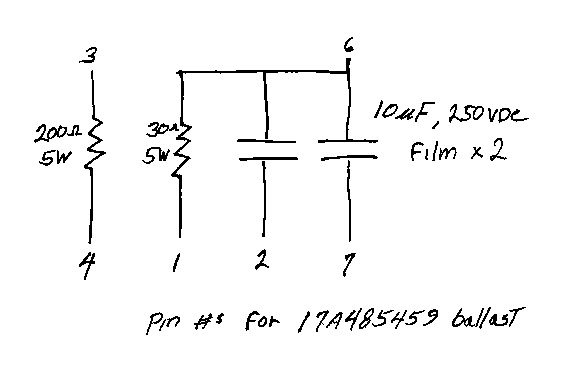
Here is a home-brew ballast that pin for pin is a direct substitute
for the 17A485459 ballast in my Motorola VT-71. It uses capacitors
in the filament strings instead of resistors. The result is 80% less
heat dissipated and elimination of the current surge at turn-on. The
tubes instead enjoy a slow, gentle life-extending warmup. A pic of
this contraption (alongside its predecessor) and a schematic are
shown below.

The math, in spreadsheet format, is as follows:

Reactance X of cap =10^6/(2*PI()*F*C)
for F=60Hz and C=10uF, X=265ohms

Resistance R of HOT filament string =260ohms.

X in series with R results in impedance Z:
Z=SQRT(X^2+R^2)=370ohms, so current at 110Vac line voltage is 110/370=.3amp

The COLD resistance of the filament string is about 50 ohms.
Substituting 50 for R in the above formula, the result is about .4amp,
+30% of nominal. This is trivial compared to the .71amp (+150%) surge
that occurs at turn-on with the original 105ohm resistor ballast.

Note: The caps shown are Panasonic ECQ-E2106KF, available from Digikey


I wish this solution had been available when I restored my VT-71.
It's smaller than my substitute and it runs cooler!
Replacing Selenium Rectifiers and Electrolytic Capacitors
Other failure-prone components in the power supply include its selenium rectifiers and electrolytic capacitors.
Selenium rectifiers look like a small stack of metal plates and should always be replaced
for safety reasons. The next photo shows how I began to mount terminal strips using the old screws which
hold the rectifiers on the chassis. The rectifier on the left (the green component with plates)
has been removed from its mount and replaced with a terminal strip.
In the following photo, both terminal strips have been mounted and I have installed two
tiny silicon diodes in place of the rectifiers.
The unused terminals on the strips were used as handy mounting points for the new
electrolytic capacitors.
Some people like to "restuff" these capacitors, removing
the innards and hiding the new components inside them (see Replacing Capacitors in Old Radios).
I have done that for certain
special radios, but in this case I simply mounted the new electrolytics under the
chassis after disconnecting the old ones. The original electrolytic cans are left
in place on top of the chassis to preserve its original appearance.
Replacing Capacitors and Resistors
This TV, and others of similar design, uses special capacitors in its high-voltage
power supply. You can get 6000-volt rated replacements (.001mfd and .0047mfd) from
Just Radios.
The rest of the capacitor replacement was uneventful.
I also checked all resistors of 1 megohm and higher. TVs of this type tend to
have several high-meg resistors associated with the picture controls (focus, centering, etc.).
The carbon resistors used fifty years ago tend to drift upward in value with age and this can have
an obvious effect on your TV's performance.
First Pictures
After I finished rebuilding the power supply, I cautiously powered up the set, using both
an isolation transformer and a variac. An isolation transformer is critical for any AC/DC
type device, to reduce the danger of electrical shock when the chassis is under power.
I was rewarded with a decent picture, as seen in the following photos.
While operating the TV on the workbench, I heard a momentary arcing sound from the neck area of
the picture tube. Quickly powering down, I took off the back of the CRT socket and saw what looked
like carbon trails from short circuits. This can be a disastrous situation, so I spent a good deal
of time cleaning every part of the socket, including removing and cleaning every one of the pins.
The CRT socket on this TV looks rather cheap to me. Even if you don't disassemble and clean it as
I did, it's worth taking a few minutes to make sure that none of the pins is so loose that it won't
securely connect with the CRT pins. Here is a photo of the socket with the back plate removed.
Later in the project, I happened to bump the CRT neck under power, and saw a big spark shoot from
the socket directly to the chassis. I quickly put a piece of temporary insulation between the CRT
and chassis to prevent that happening again. This is not a problem when the TV is installed in
the cabinet, since then it is suspended well away from the chassis.
After I finished recapping the TV, I went on to replace all resistors rated 1 megohm or higher.
By the time I finished, the set seemed to be working beautifully.
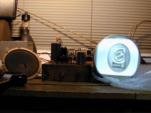
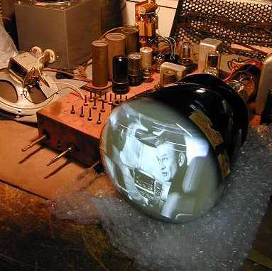
The next two photos are
links to short MPG movie files. The Marilyn Monroe clip was captured while playing a DVD of "Some Like It Hot"
on channel 3. The second clip is an on-air broadcast.
(If you have a fast Internet connection, click on the
photo to play the clip. If you have a slow dial-up connection, you may prefer to right-click on
the photo and save the MPG file to your local computer, then play it from there.)
The movie clip sounds buzzier than the on-air clip. This often happens when feeding output
from a modern video device to a vintage TV. The modern signal may overload the TV, resulting in the
same sort of audio buzz that you'll hear on most any TV (new or old) when it happens to display an
extremely high-contrast picture, such as large black words on a pure white background. You can
reduce the buzz by installing an attenuator between your modern DVD or video player and your old TV.
Replacing the Picture Tube Gasket
Almost every Motorola VT-71 or VT-73 TV has a deteriorated CRT gasket. The gaskets were made of an early
synthetic material that deteriorates badly over time. Since there is no source of factory original gaskets, the restorer needs to make a substitute.
The original gaskets had a bell shape toward the rear, into which the CRT would fit, and a lip around
the front edge, which would slip around the front cabinet opening. You can see photos of an original gasket on Steve Reeves'
VT-71 page.
I don't have any way to cast such a
fancy object in rubbery material, and I didn't have even part of an original to use as a pattern. The
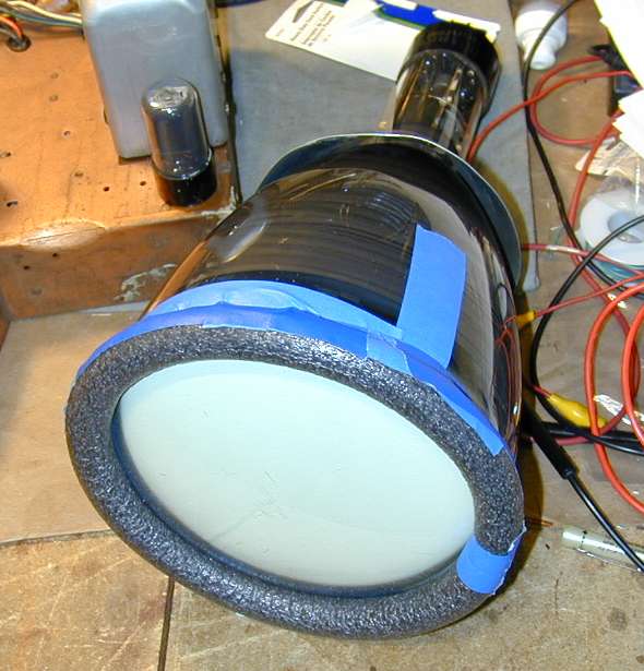
next photo shows a temporary substitute that I made to hold the CRT while taking some photos.
The temporary gasket is a circle of round insulating foam, held onto the CRT with masking
tape. It held the tube in place long enough to take some photos, but something more permanent was obviously needed.
For the second version, I removed the gasket from the CRT and permanently glued the foam circle to the cabinet
opening. Then I built up an extra support below the CRT bottom by stapling short sections of the same material
to the cabinet. The result is perfectly functional, although it doesn't provide a rectangular mask in
front, as does an original gasket.
On these TVs, you may often find some stuck-on residue from a deteriorated gasket on the cabinet
or chassis. It can easily be cleaned up with rubbing alcohol or even water.
Years after I first published this article, a fellow hobbyist started
making reproduction gaskets. You can buy them from
Renovated Radios.
It Ain't Over 'til It's Over
The next photo shows the restored chassis. The five long white objects in the lower left are the
new high-voltage capacitors.
At this stage, I considered the restoration complete and installed the set in the cabinet. The
next movie clip shows the restored TV playing on my office desk.
Alas, my joy was to be short-lived! After a couple of days of enjoying the TV, the picture suddenly shrank
to about half the normal height. Even worse, it lost focus and became very blurry. Reluctantly hauling to back to the workbench, I embarked
on a long detective expedition, testing and replacing components around the 6SL7 vertical output tube
and other likely spots.
With some patient advice from Bonita, I finally discovered the culprit. One of
the pair of 6.8-megohm resistors that I had replaced on the 6SL7 tube plates had gone bad. When I
replaced it, the focus and vertical height popped back to normal.
In the course of that testing, I also noticed a couple of occasions in which the 6SL7 tube started to
arc with blue sparks inside the tube! Examining the tube socket, I could see a lot of discoloration
that looked suspiciously like arcing trails, particularly around the plate pins (2 and 5), which
carry high voltage leading to the 6-kilovolt CRT vertical plates.
Although the vertical height and focus were back to normal, the TV still showed some vertical jitters,
plus—more ominously—intermittent blips that disturbed both the vertical and horizontal stability.
I decided to disconnect everything from the 6SL7 socket and replace it.
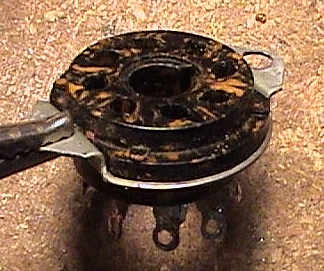
The next photo
shows the deteriorated socket. Look at the orange-brown trails burned into the original black phenolic
insulator. These are not surface defects. If you scrape the surface with a sharp blade, you'll see that
the discoloration goes deep into the insulating material.
Arcing problems can be tricky to locate. In some cases, you can power up the set in a
completely dark room and see where the arcing occurs. It may help to loosen a tube slightly in its
socket and peer underneath to look for sparks in the dark.
Some times, however, the arcing may
be taking place farther down inside the socket structure, along a path that's not visible from
either side of the chassis. While you should be able to detect the problem with careful voltage
measurements at the socket, it may take less time (and risk less damage) to simply put in a new
socket.
Replacing a Tube Socket
Replacing a tube socket is tedious, but not particularly difficult. I always start by drawing a little
diagram of everything connected to the tube.
You should also refer to the schematic, of course, but
I feel more confident of getting everything reconnected correctly when I have drawn my own picture.
Sometimes there are connections to a tube pin that are not immediately obvious from the schematic,
as when an unused pin is employed as a connecting point for two things not closely related to that tube.
After you disconnect everything, you can carefully drill out the rivets holding the socket to the
chassis. I drill from the underside. Be extremely careful while doing this. Be sure that the chassis is securely supported on
your workbench and don't use too much pressure. Make sure that all loose leads are pushed or taped well away
from the drill bit. You can wreck things or hurt yourself if a loose lead suddenly wraps around the
whirling bit!
You also need to avoid blowing too much metal dust and chips around inside the chassis. I usually
stop a few times in the course of drilling out each rivet, to suck up metal dust with a little
shop vac. When all the drilling is done, I carefully clean the area using alcohol on a Q-tip swab.
You will be able to tell when the drill has removed enough material to release the rivet. Be
careful not to push too hard on the drill toward the end. The bit may pop through into the old socket's mounting hole (or
the hole in the chassis) and suddenly jam.
When the old rivet is free, you can push it out from underneath.
After you have removed the second rivet, you are ready to install your new socket with screws and reconnect everything.
Falling Off the Wagon Again!
After I installed the new socket, the TV seemed to be playing fine again. The voltages on the 6SL7
tube were right on the money, and the picture was crisp and stable. Just to make sure, however, I
decided to give it a nice long bench test. I set up the TV on a card table in our bedroom and turned
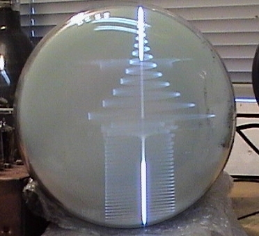
it on during an evening when we planned to watch several shows. To my dismay, it conked out again
after only a few hours!
This time, the horizontal width collapsed almost completely and the vertical rolled wildly with a sort
of oscilloscope-like pattern. The next photo gives you an idea what it looked like.
This was discouraging, since I had considered the set "fixed" quite a while ago.
Checking tubes and swapping them around didn't cure the problem, so
I put my detective's hat back on and started searching out the cause. The problem
certainly lay somewhere in the sweep sections, but it wasn't immediately clear whether it
was limited only to horizontal or affected both horizontal and vertical.
A problem that affected both horizontal and vertical could lie in the clipper tube, so I started
checking voltages and components there, finding nothing obviously wrong. Then I moved to the horizontal
sweep section. The voltages on the 12SN7GT horizontal AFC/oscillator tube were way off! After
some checking, I discovered that a tiny mica capacitor (C138 on the original Rider's schematic)
had shorted out.
Mica capacitors are usually very reliable, so much so that I don't bother testing them unless
I have a specific reason to suspect one. This guy had definitely failed, however. As soon as I replaced it, the picture
popped back to normal. Whew!
This time, I vowed to leave nothing to chance, giving the TV a bench test lasting several hours
at a time, repeated over several evenings. After surviving a few days of "torture testing," the
set appeared to be stable, so I put it back together.
Final Thoughts
This project required a lot of patience. I have learned, in the course of restoring several old TVs, that
you often need to do a lot of work before you are rewarded with any sort of decent picture. The average
tube TV is much more complex than the average tube radio, with more tubes and other components.
TVs also need to meet very exacting requirements in order to function at all. The horizontal sweep
section must produce a sawtooth wave of exactly 15,750 cycles per second! As this project demonstrated,
the picture can collapse entirely if only one tiny component goes bad.
My general approach with TVs is the same as for tube radios. I start with the power supply, since
it's pointless to try diagnosing other problems until you know that all the other circuits are
receiving the power that they need. After I had restored this power supply, I gently powered up the
TV and saw a surprisingly good picture, but the project was far from over.
The next phase is to methodically replace all electrolytic and paper capacitors, as well as all resistors
with values 1 megohm or higher. Pay special attention to the voltage ratings of capacitors. For radios,
you can usually replace all non-electrolytics with 630-volt rated capacitors and forget about the voltage
rating. Sure, you may replace some 150- or 350-volt rated capacitors with sturdier components than the
originals, but life is simpler if you stock all 630-volts. For TVs, you may need
to use a few capacitors rated for thousands of volts, so you need to pay attention.
You should also be prepared to test and replace lower-value resistors that you wouldn't normally look
at in a radio project. Again, higher voltages and frequencies can lead to breakdowns that you
wouldn't experience in a simple tube radio.
Having replaced those components, it's reasonable to power up the set and see what happens, then go on to diagnose and
fix any remaining problems. Even if the set seems to be working well, it's time for an extended shakedown
cruise.
In this case, the TV suffered two major relapses after the point when I thought I was finished.
The first relapse (shrunken vertical and loss of focus) was caused by the failure of a new resistor
that I had previously installed, which only proves that you shouldn't take anything for granted.
The second occurred when one of the original mica capacitors finally gave up the ghost.
Every project must come to an end, and this one eventually had a happy conclusion. The Golden View
played nicely and I enjoyed using for a few years before trading it to another collector.
Even a well-restored 55-year old television won't perform exactly
like a modern solid-state set, of course. You should be prepared to adjust the fine tuning and
brightness when changing channels, and virtually every tube TV may need to be serviced
once a year or so, just as when they were new. It's loads of fun to watch these tiny old sets,
which greatly helped to popularize the new-fangled medium of television in the early days.
|