Emerson Model 609 Projection Television (1949)


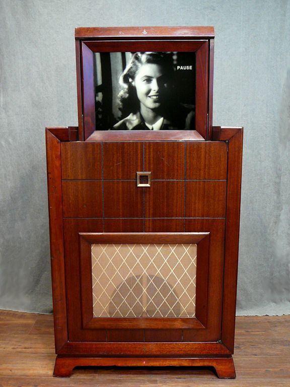
This 1949 Emerson Model 609 television is my first projection set. It
looks different than any TV in my collection and it employs some
fascinating technology.
Finding an Emerson 609
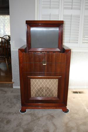
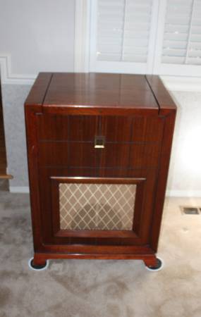
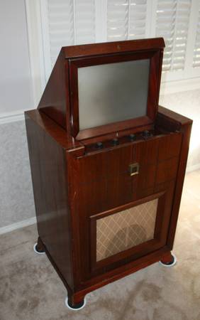
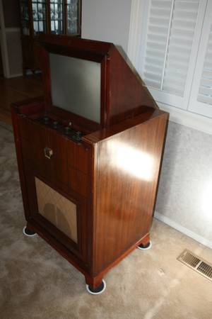
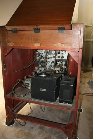
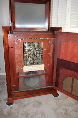
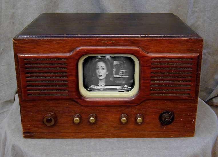
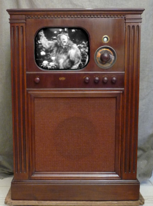
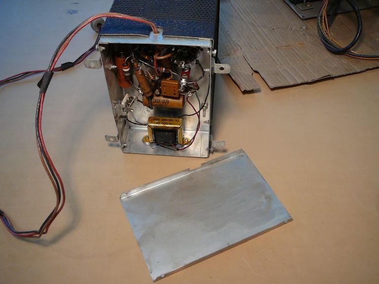
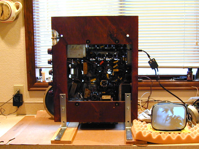
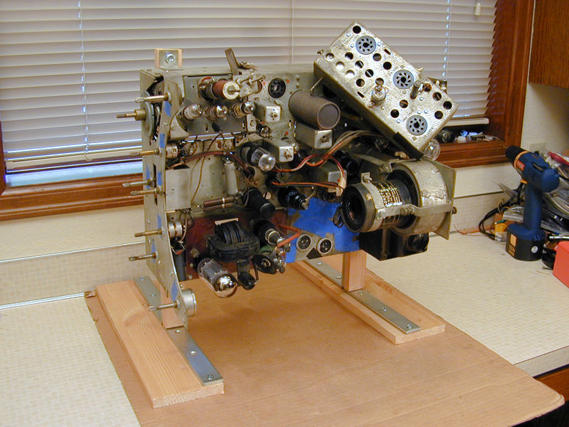
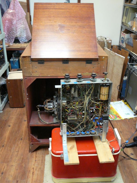
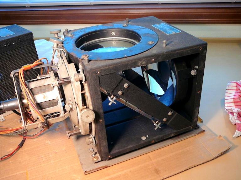
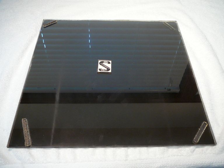
In the summer of 2016, I noticed this TV on our local craigslist site.
Here are photos from that listing:


At the time, I was embroiled in another complex project (my
DuMont RA-102) and I didn't have space
for another big console. Perhaps, I thought, some other TV collector will buy the Emerson
and restore it, so I don't have to worry that it'll be tossed in a dumpster or
"repurposed" into some Flea Market Flip horror like an aquarium or
liquor cabinet.
After a few weeks, the TV was still unsold, and the seller dropped the price.
I went to inspect the TV and ended up buying it. The set looked complete
and unabused, and I was intrigued by the unfamiliar projection modules.
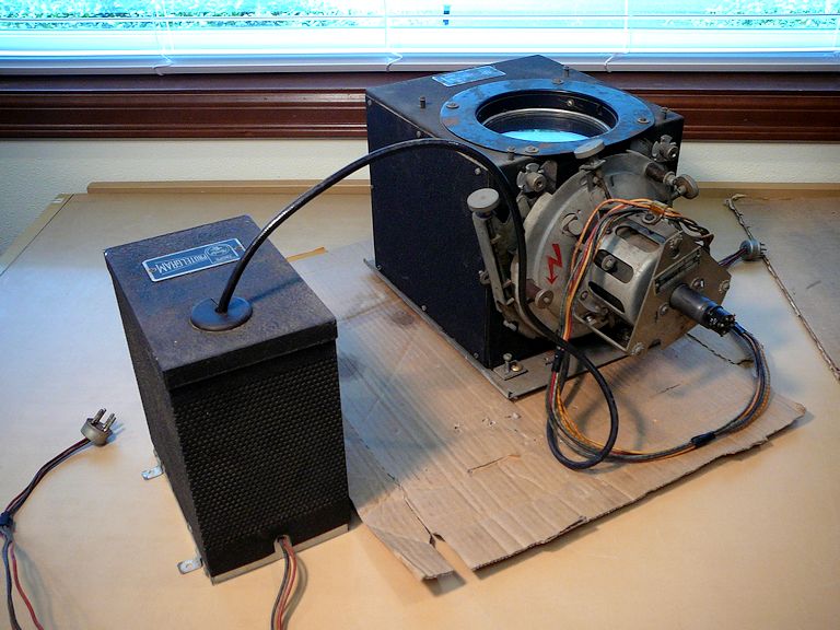
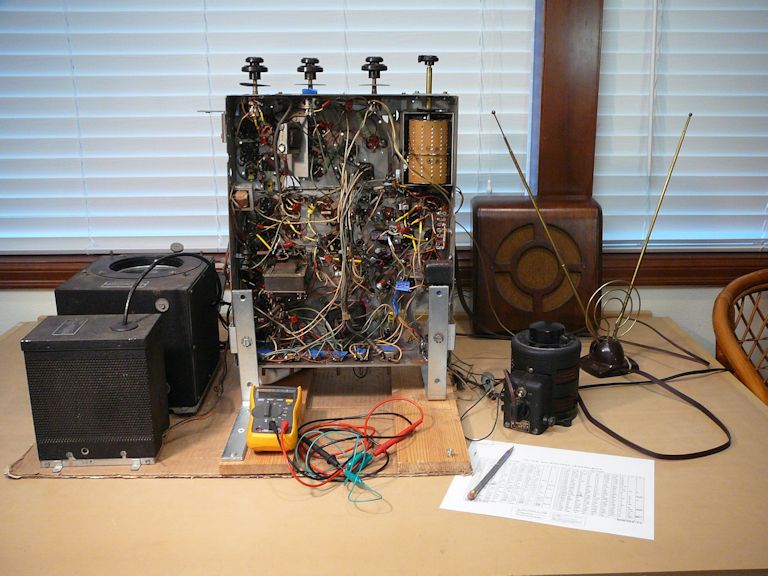
Transporting this big, heavy TV was a challenge. I removed the two projection
modules to reduce the weight in the cabinet and made sure that everything else
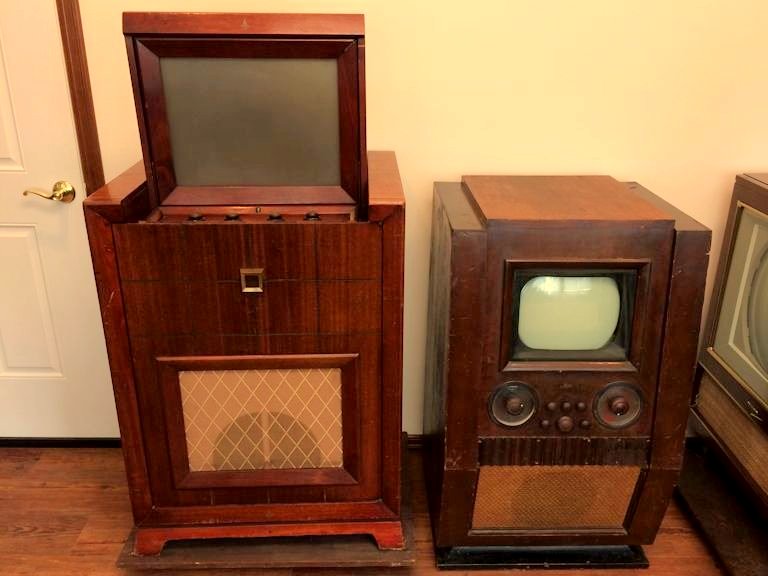
was screwed down securely. In this photo, the newly arrived 609 sits next to my DuMont RA-102:

The Emerson's screen is much bigger than the 12-inch CRT in the DuMont set.
That's what projection TVs are all about!
Description
In the 1940s, as in later years, most TVs were the "direct view" type,
meaning that you look directly at the face of the picture tube.
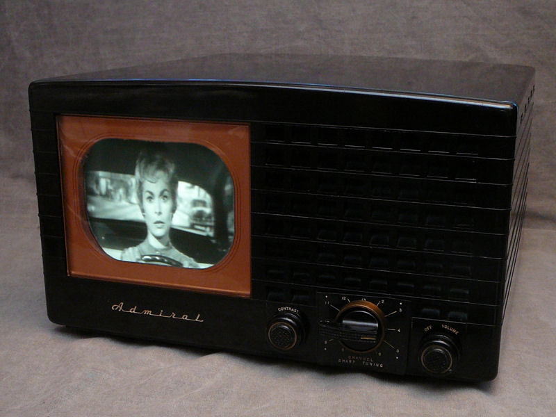
But 1940s picture tubes were small by modern standards. Tabletops like
my Admiral 19A12 or
National TV-7W used
a 7-inch CRT, smaller than the span of your hand.


Consoles had bigger 10-inch or 12-inch tubes,
as in my DuMont RA-103
or Philco 49-1240:
Projection TVs allowed manufacturers to break the bounds of direct-view CRT technology. By reflecting the
image onto a large screen, they could make a display larger than any direct-view tube.
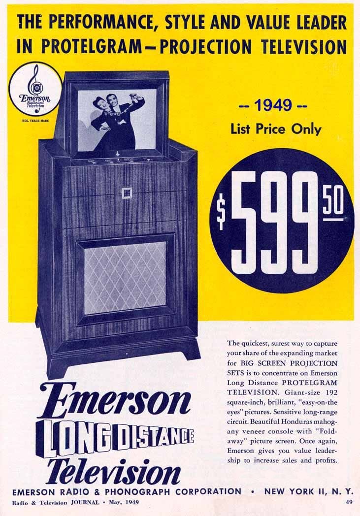
My Emerson 609's screen measures 12 x 16 inches, with a diagonal measure of about 20 inches, or an
area of 192 square inches, as touted in this ad:
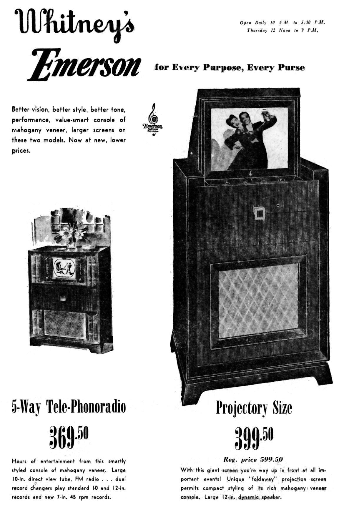
A second ad comes from a newspaper in Menands, New York. The 609 is
presented with its "projectory size" screen, and a reduced price of
$399.50, some $200 cheaper than its original list price. Perhaps this ad appeared
late in the 609's product life, when Emerson discounted the sets to make way
for newer models.
The 609 was sold for only about two years, from 1949-1950. By 1951, advancements
in direct-view picture tube technology made bigger screens affordable. Emerson
and other makers wasted no time in churning out TVs with screens as big as 20
inches diagonally, making projection TVs like this one obsolete.
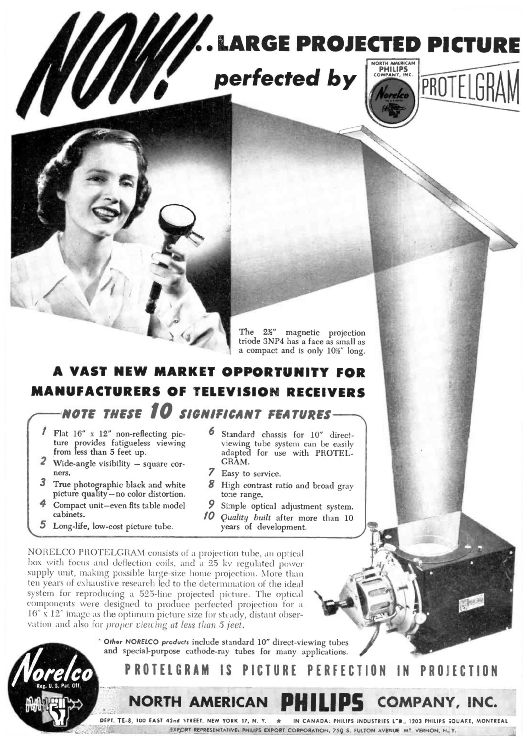
The Emerson uses a Norelco Protelgram projection unit as shown in
this 1948 ad from North American Philips:
The Protelgram employs a tiny
3NP4 picture tube,
operating at the extremely high voltage of 25 kilovolts.
The aluminized 3NP4 tube makes a very brilliant image, which is reflected in a system of three
mirrors onto a translucent viewing screen. We'll learn more about the complex optics
later in this article.
The Emerson 609 television uses 30 tubes in three chassis:
| Tube |
Type |
Function |
| V1 |
6AG5 |
RF Amplifier |
| V2 |
6J6 |
Converter |
| V3 |
6AU6 |
1st Video IF Amplifier |
| V4 |
6AU6 |
2nd Video IF Amplifier |
| V5 |
6AU6 |
3rd Video IF Amplifier |
| V6 |
6AU6 |
4th Video IF Amplifier |
| V7 |
6AL5 |
Video Detector/AGC Rectifier |
| V8 |
6AU6 |
Video amplifier |
| V9 |
6AQ5 |
Video Output |
| V10 |
12AU7 |
Cathode Follower/DC Restorer |
| V11 |
6AU6 |
Audio IF Trap |
| V12 |
6AU6 |
Limiter |
| V13 |
6S8GT |
Discriminator/Audio Amplifier |
| V14 |
6V6GT |
Audio Output |
| V15 |
12AU7 |
Sync Amp. / Sync Separator |
| V16 |
6SN7GT |
Sync Phase Inv. / Horiz. AFC |
| V17 |
6SN7GT |
Vert. Osc. / Vert. Discharge |
| V18 |
6K6GT |
Vertical Output |
| V19 |
6AL5 |
Horizontal Phase Detector |
| V20 |
6SN7GT |
Horiz. Osc. / Horiz. Discharge |
| V21 |
6BG6G |
Horizontal Output |
| V22 |
5Y4G |
Damper |
| V23 |
6SC7 |
Scanning Interlock |
| V24 |
6SR7 |
High Voltage Oscillator |
| V25 |
6BG6G |
High Voltage Output |
| V26 |
5Y3GT |
Low Voltage Rectifier |
| V27 |
EY51 |
High Voltage Rectifier |
| V28 |
EY51 |
High Voltage Rectifier |
| V29 |
EY51 |
High Voltage Rectifier |
| V30 |
3NP4 |
Projection Tube |
Here are two service manuals for this set. The Riders manual is from TV Volume 8,
Emerson pages 1-3. The Sams manual is from Set 90, Folder 6. To download a manual,
right-click on its icon and choose Save Target As:
 Riders Riders
 Sams Sams
If you're restoring a 609, I recommend using both manuals, since each has certain
info not found in the other. The schematics are also drawn somewhat differently, and you may find
one style easier to read.
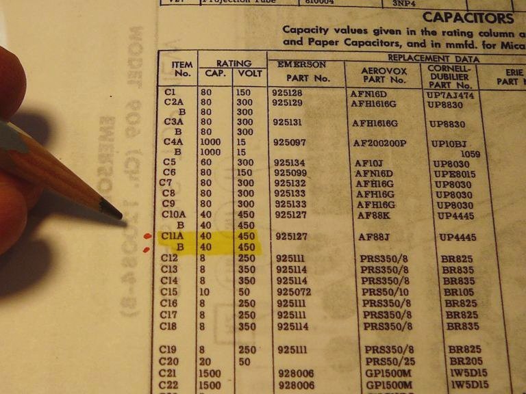
In this article, I'll refer to components by their Sams part numbers.
First Look
After bringing the 609 home, my first task was to make a closer
inspection and pull the chassis. You can reach the chassis from
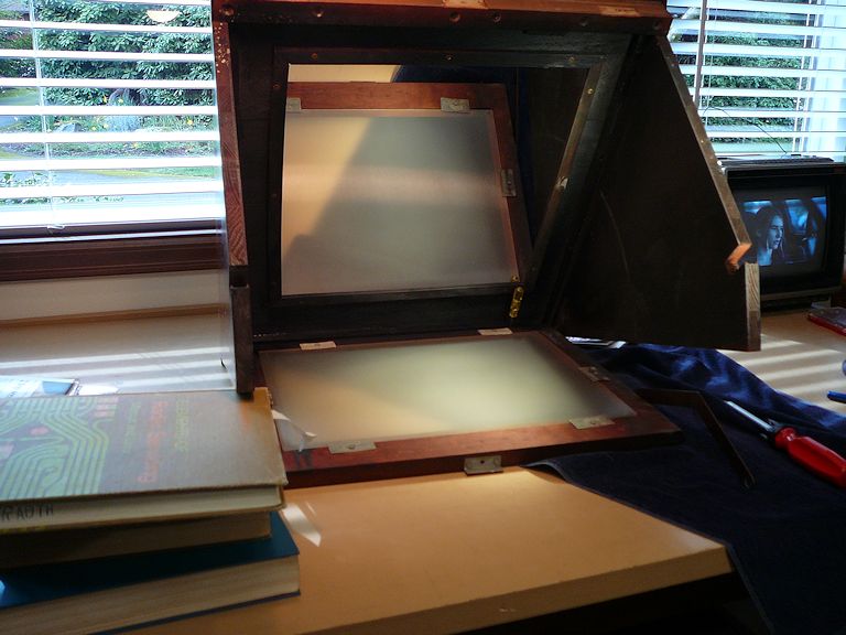
behind after removing the rear cover. The front of the cabinet also has a hinged panel
that swings out for service adjustments.
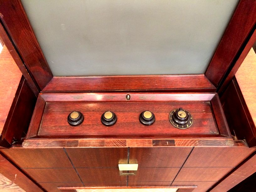
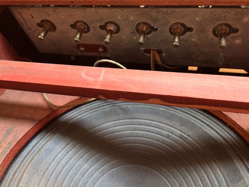
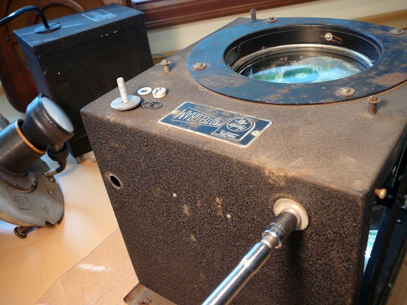
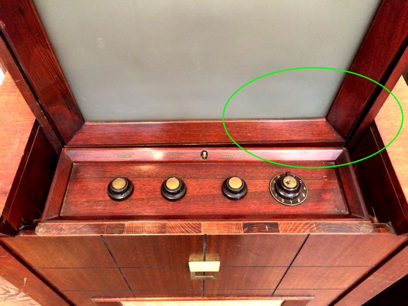
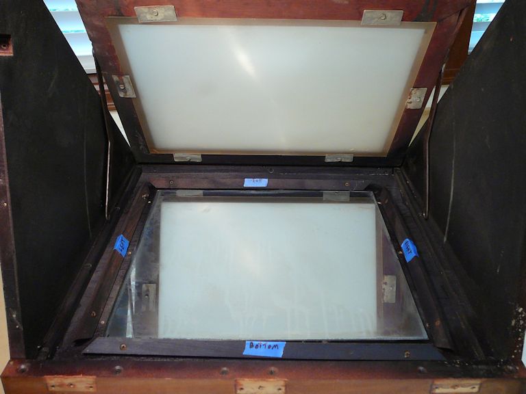
The top-mounted knobs are all present and in decent shape. This control panel is
revealed when you lift the screen into viewing position:

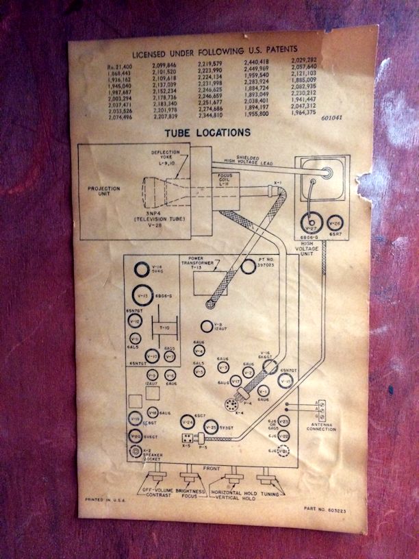
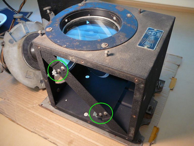
The 609 labels are also present:

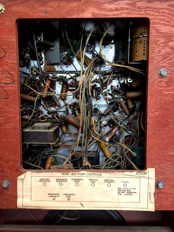
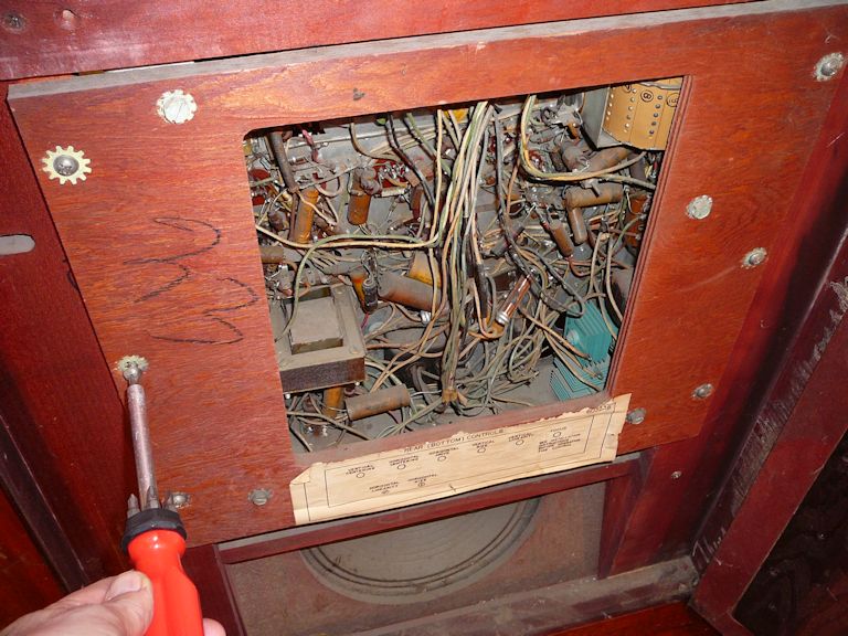
As shown in the second label, there are eight controls under the chassis to adjust
image parameters like centering and linearity:

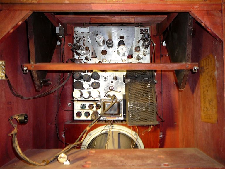
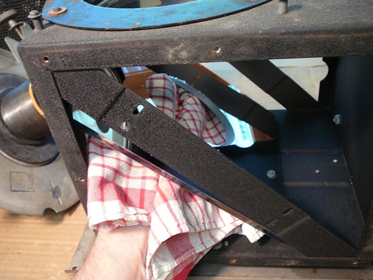
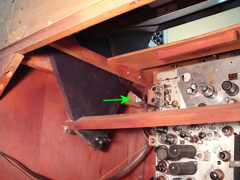
The next photo gives a closer view of the main chassis inside the cabinet. The Protelgram projector
modules normally sit on the shelf behind the main chassis, but I had previously removed them
for transport.

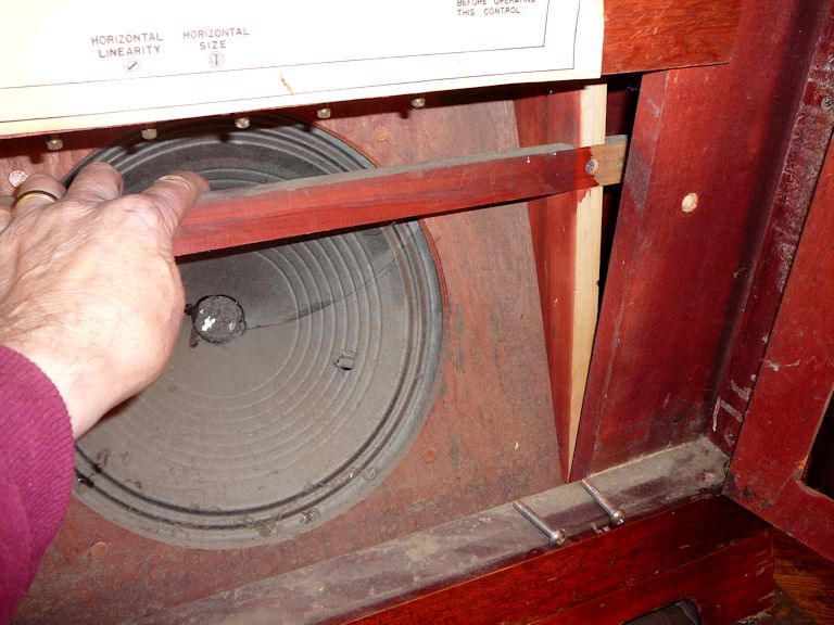
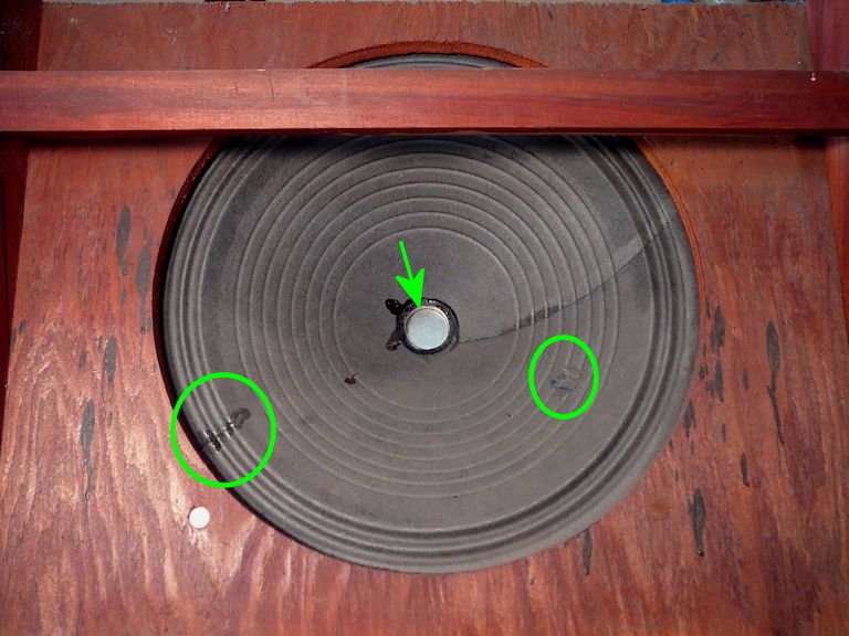
The 12-inch speaker is mounted on a hinged frame that swings back and down after
you remove a couple of screws. You must lower the speaker to make room to remove the
main chassis:

While the speaker is in lowered position, it's important to protect its paper cone with a towel or
a square of cardboard, to prevent damage if something drops onto it.
My cone has an old poke and a previously-glued tear; I'll fix those later with
tea bag paper and flexible glue.
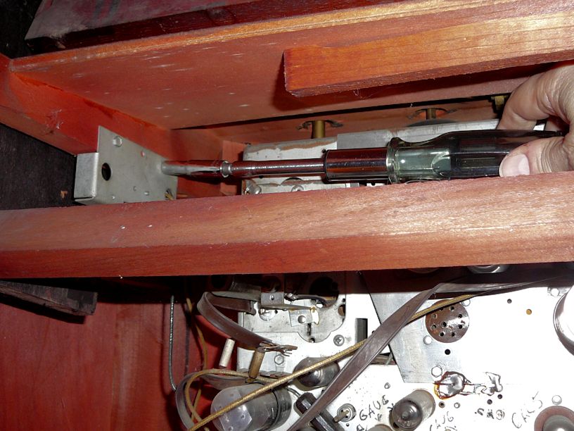
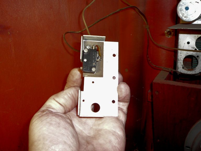
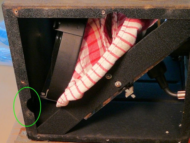
Removing the main chassis means detaching several items, including the power interlock
tucked way up in the top. This momentary-contact switch automatically cuts the power when you lower
the screen:


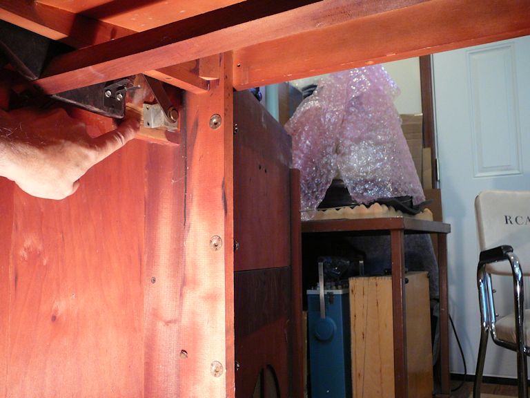
I have removed the knobs and detached all cables. Now I can lift out the main chassis after
removing six screws, three on each side of the wooden chassis sub-frame:

Pulling the chassis is easier with a helper.
If you're working alone, you'll need to support the entire chassis' weight with the fingertips of
one hand, while removing the final screws with the other. Brace the bottom edge of the heavy chassis
with your leg when it swings out toward the front; if you let it swing too far, the control shafts on
top of the chassis might mash against their cabinet holes, bending or damaging the controls.
Before lifting out the chassis from the front, you'll also need to secure the tangle of
disconnected cables hanging off its rear. Either tape the cables in place or tuck them into
crannies between tubes and transformer covers, so they don't snag
and tear loose when you pull the chassis out through the front.
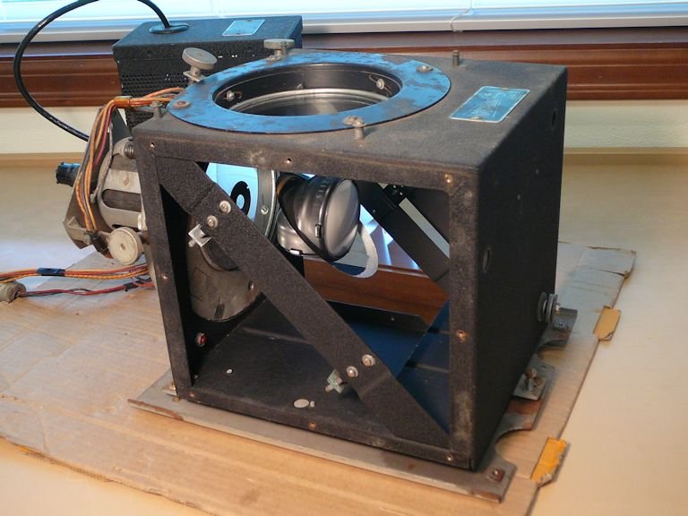
In the next shot, I have removed the main chassis, complete with its
wood sub-frame. I'll leave the speaker in the cabinet for now. When restoring the electronics on the workbench,
I'll use a test speaker.

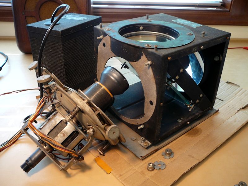
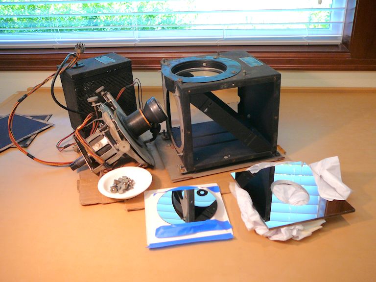
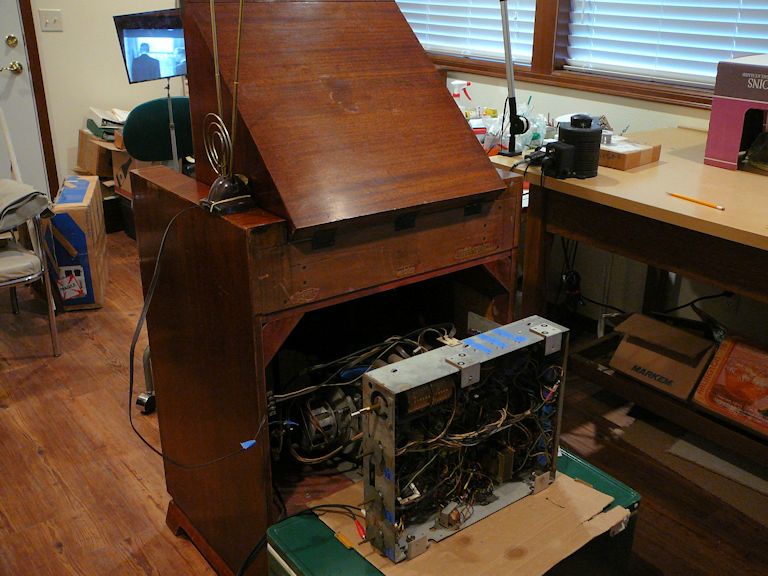
Finally, I can see all the Emerson 609 chassis together. On the left are the
two mysterious black modules comprising the Protelgram projector. The main chassis sits to
the right, still mounted on its sub-frame:
Let's go to work!
First Steps
In every project (see First Steps in Restoration),
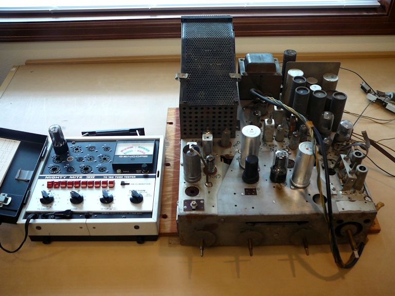
I start by cleaning the chassis and testing the tubes as I go. Here, I'm testing
tubes on the main chassis:

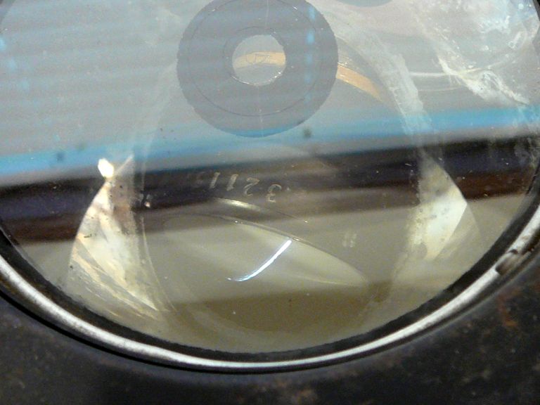
I'd normally check the CRT, too, but my Sencore CR70 tester has no data
for a 3NP4 picture tube. Other collectors have told me that 3NP4s tend
to be rugged, so for now I'll assume that mine is good.
As in many restorations, nearly all the tubes on the main chassis were good enough to use.
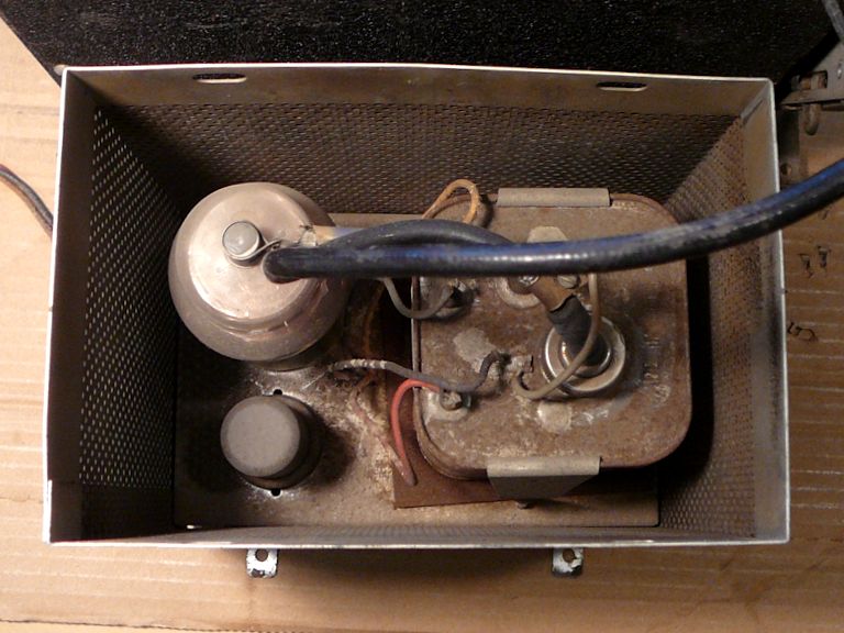
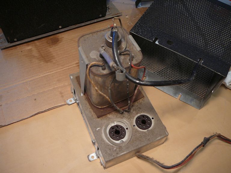
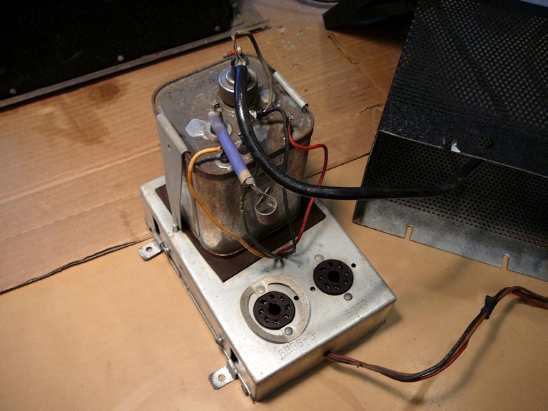
There are two more to test inside the Protelgram's high-voltage chassis. It's dusty in there!

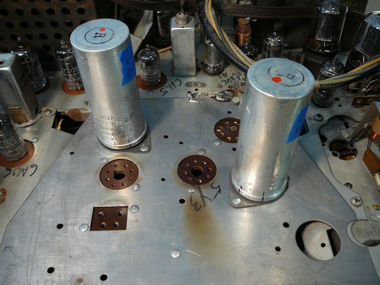
This chassis was easy to clean after I removed the HV cage. In these shots, the
two empty sockets are for type 6SR7 and 6BG6-G tubes, which I already confirmed
as good:


On this chassis, the big metal can is sealed and filled with oil. Inside it is a transformer
and three small EY51 rectifier
tubes, and together they provide the final HV output of a whopping 25 kilovolts. Talk about
a black box! This sealed unit has a reputation for reliability, so I'll assume it's OK for now.
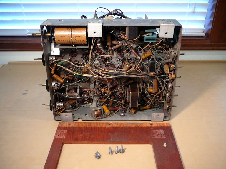
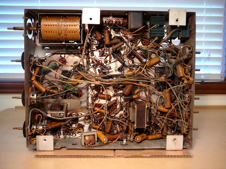
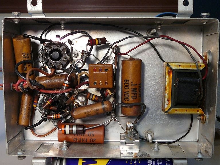
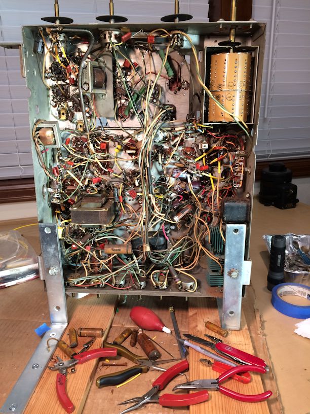
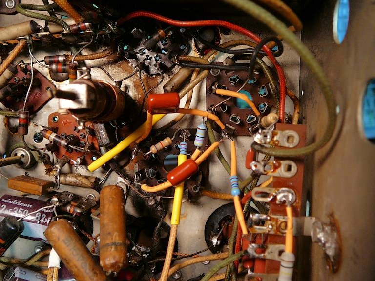
Now, I can remove the chassis sub-frame and get a close look at the underside:


In these photos, the user controls are seen at the left. In the upper left corner is the
sturdy turret-style tuner. The finned green components at upper right are selenium rectifiers.
Sprinkled everywhere, we see paper capacitors (the tan cylinders) and a few electrolytic
caps, all of which will be replaced in due course.
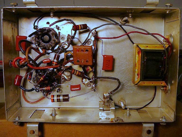
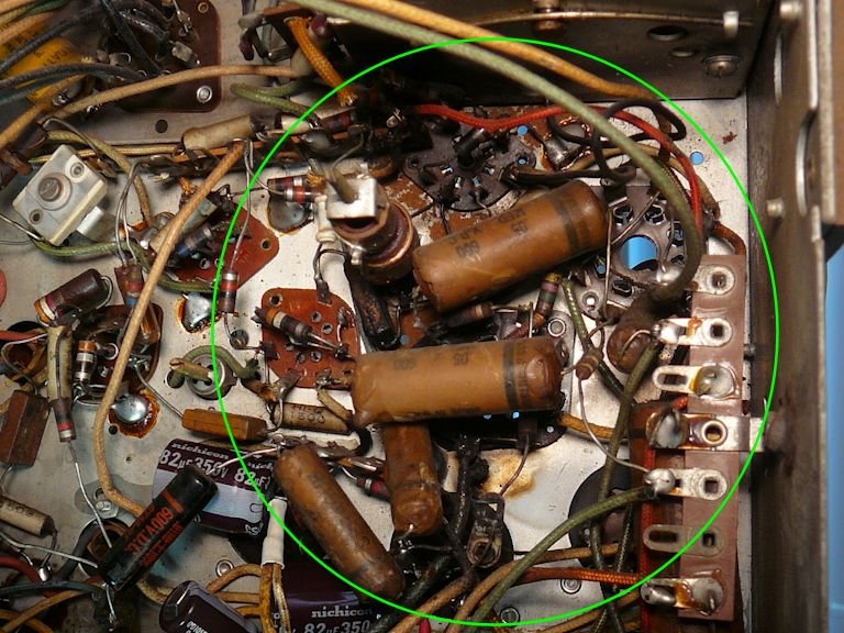
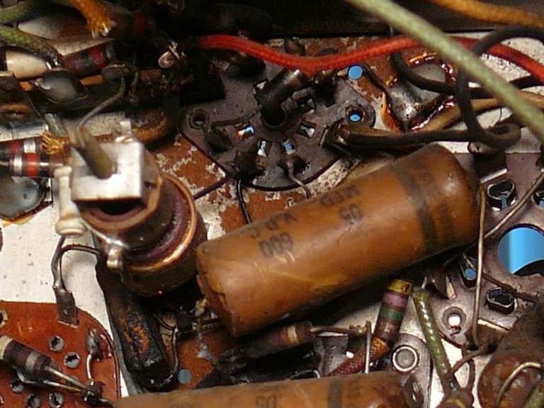
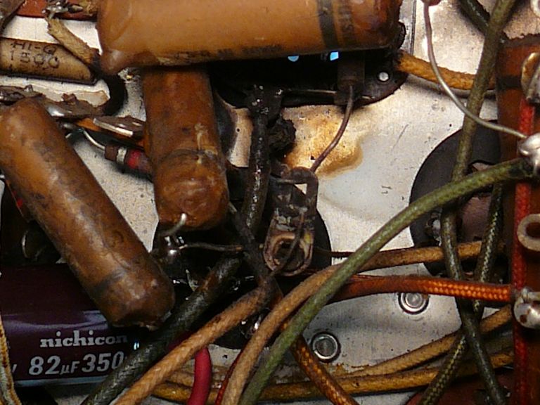
At first glance, this chassis looked unspoiled, but on close inspection, I saw
that part of the chassis had suffered a fire—or, at least a "smoke-out"—that
blackened resistors and other components. This crowded area is tucked up under the tuner
turret and it is difficult to see, much less photograph:

We'll return to this accident scene later. Meanwhile, traveling around the chassis, I found
several slipshod "repairs," two of them on the edge of the charred zone.


Did one of those sloppy, uninsulated wires make a short circuit and cause the meltdown?
There's no way to be sure. I'll look carefully for more monkey
business as I proceed. Luckily none of this damage appears
to involve precious, "unobtanium" components.
Replacing Capacitors
Recapping (replacing capacitors) has been described many times in this website, so
I'll cover a few highlights specific to this set and refer you to my recapping article
for the basics.
Let's start with an easy section under the Protelgram HV chassis:


This little chassis has only five paper caps and one electrolytic. The job is
soon done:


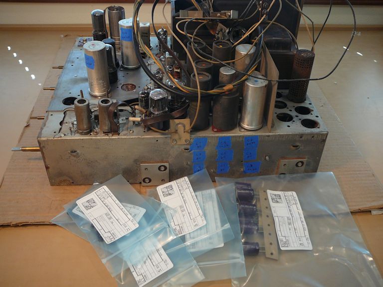
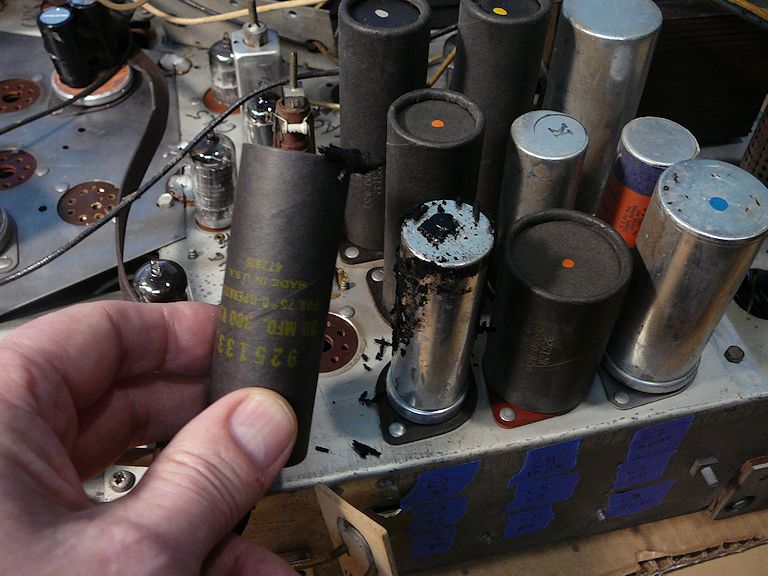
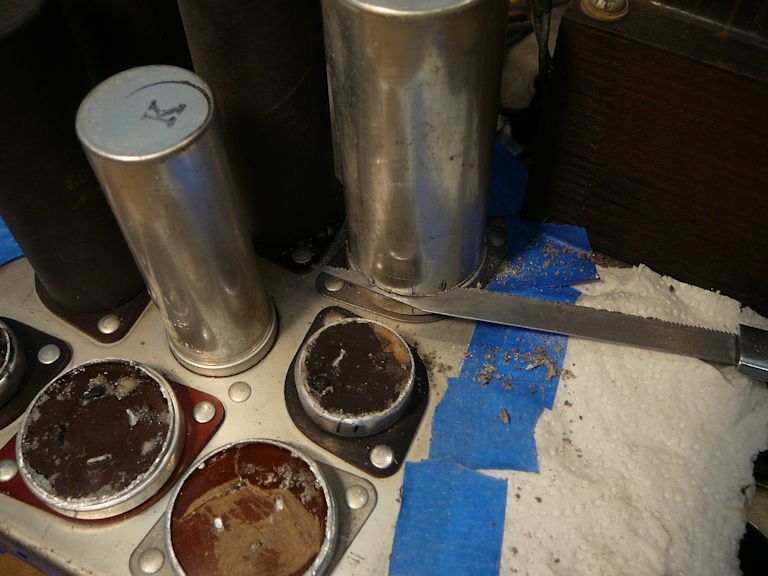
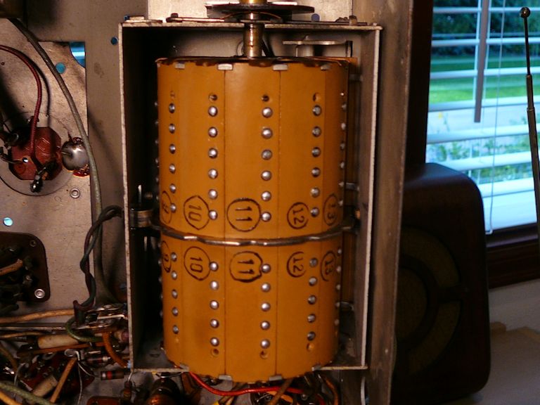
The main chassis holds a lot of electrolytic capacitors, 25 in all. On its top side, we
find 11 cans containing a total of 16 caps:

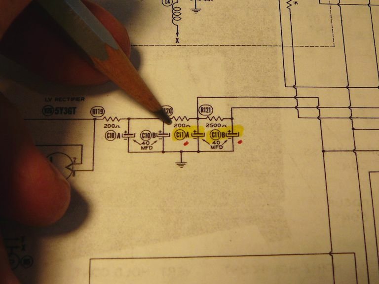
The C10 and C11 containers are cut open and restuffed with new caps:


I check off each component in the docs as it is replaced:


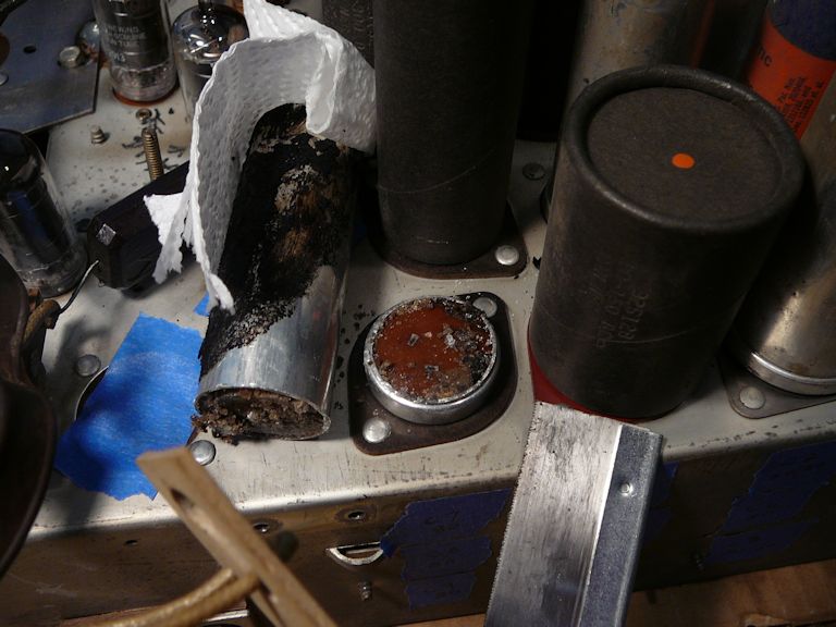
In this large bank of nine cans, five are housed in cardboard covers, which can be
pulled free after you soften their tarry adhesive with a heat gun:


It's important to preserve the cardboard covers because their metal cans are above
ground potential when the TV is powered, and they would present a shock hazard if left uninsulated.
Notice how the cans with cardboard covers are mounted on insulating phenolic pads. The
pads isolate the can's bottom from the chassis, in contrast to bare cans that are grounded
directly to the chassis via rivets or twist prongs.
Most of the containers could be cut with a narrow craft saw, but reaching the innermost ones
was more trouble than it was worth. For those, I disconnected the old caps and wired new
ones under the chassis, leaving the original cans undisturbed above the chassis for appearance.


After dealing with the cans, I replaced the other electrolytics wired under the chassis.
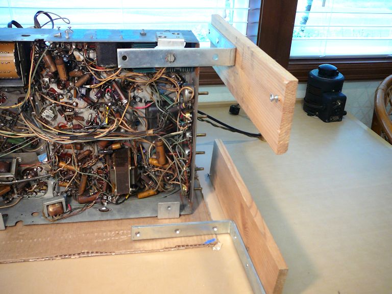
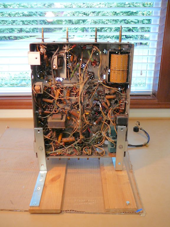
You can reach many components with the chassis lying on its
side, but the rest of this task will be easier if I mount the chassis
on sturdy legs:

If those legs look familiar, it's because I have used them many times, in projects
like my DuMont RA-113 and
Capehart-Farnsworth 661P TVs.


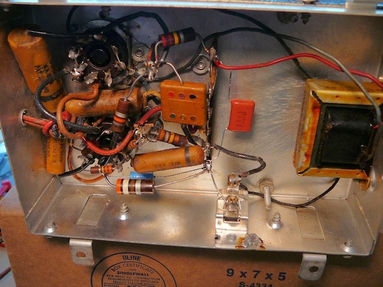
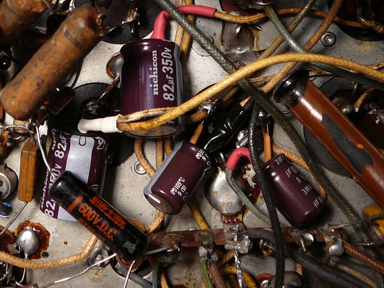
Replacing the paper capacitors took hours. In this photo, I'm
nearing the finish line:
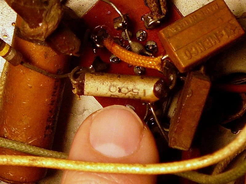
This TV has several small white ceramic capacitors like the one pictured here:

These are reliable, like ceramic disc caps, so I won't replace any unless
a specific problem suggests that one is bad. I'll take the same approach with
mica caps like the two tan rectangular units in the last photo, although
I'll look closely at micas in the horizontal sweep circuits, where they fail most often.
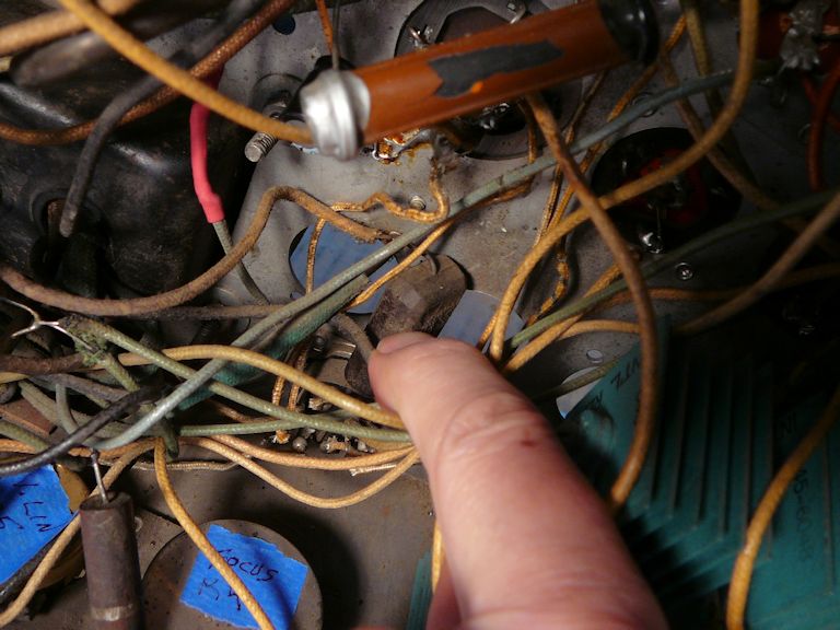
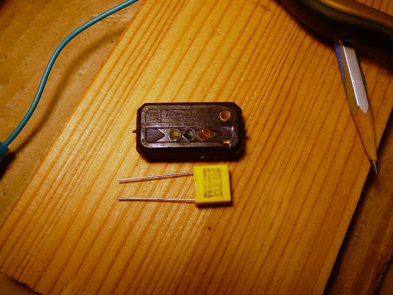
Buried under wires near the finned selenium rectifier is the easily-overlooked line filter cap,
labeled C103 in the Sams schematic:

This rectangular unit is a paper cap in a plastic shell, very unreliable. Its purpose is to
filter out interference coming in through the AC power line. Left in place, these caps have a nasty habit
of exploding when they fail, so I'll replace it with a special
line filter cap like the one shown here:

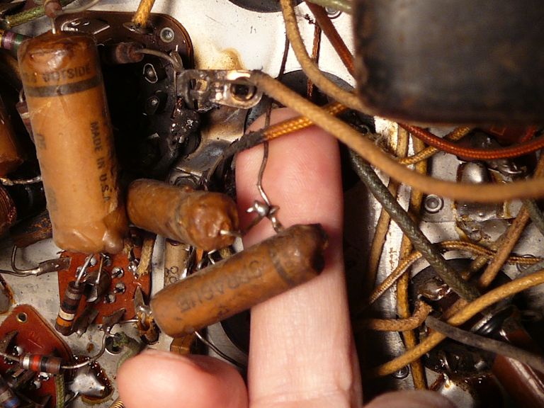
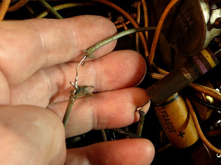
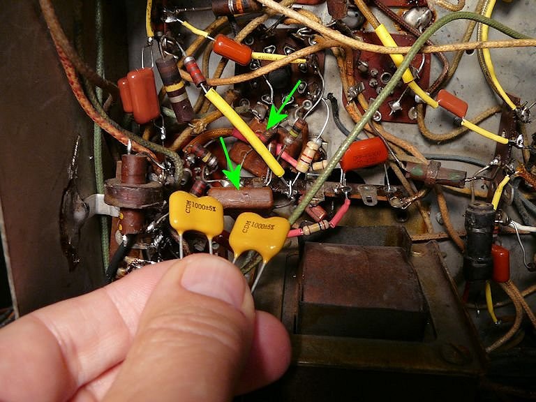
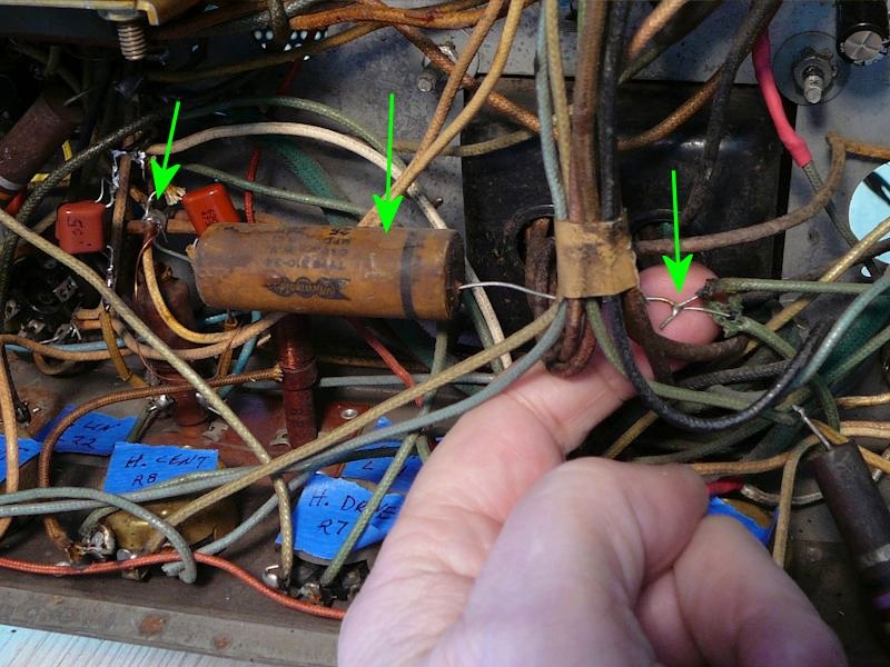
During recapping, I continued to find crude work like this uninsulated junction (we'll read
more about this installation later in this article):

Notice the messy wires trailing everywhere in the previous photo.
This TV is just plain annoying to service, with mats of unruly wires blocking access to components
at many spots.
In a thoughtfully-designed TV or radio, long leads are placed against the chassis wherever practical, to suppress
interference and simplify service. In high quality military or industrial equipment, long leads are strapped into
neat bundles and carefully routed along the most effective path near the chassis metal; it's as if
the entire wiring harness was installed first, and then the chassis was populated with components.
This Emerson is quite the opposite, with leads flying in the breeze nearly everywhere you turn. It's
as if they installed all the components first, and then connected the long wires as an afterthought.
This helter-skelter construction, along with the complexity of the optical and high-voltage sections, is why I would never recommend
the 609 as a beginner's project.
Repairing Fire Damage
Perhaps "fire damage" is an exaggeration, but I need to attend to the black,
scorched area discovered earlier. I'll do this while replacing the paper caps in that zone, which
is in a corner under the tuner frame, near the
sockets of two video IF tubes (V3, V4) and two vertical sweep tubes (V17, V18):


After scraping and brushing away scorched material, I saw that the damage wasn't as
bad as I feared. Testing showed that the sockets and video IF transformer
were not compromised. Slowly and methodically, I began to replace all the
resistors and capacitors in that area. In the next photo, I'm partway through
that process:

After more work, that scorched corner looked much better. When I'm able to power up the TV, I'll do more checking
to confirm the repairs were successful.
With that, I declared the initial recapping finished!
Can We Turn It on Yet?
I'm eager to try out this TV, but first I must address some power-supply components:
the ballast and the selenium rectifiers.
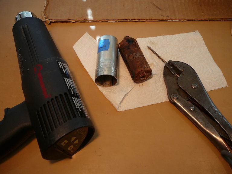
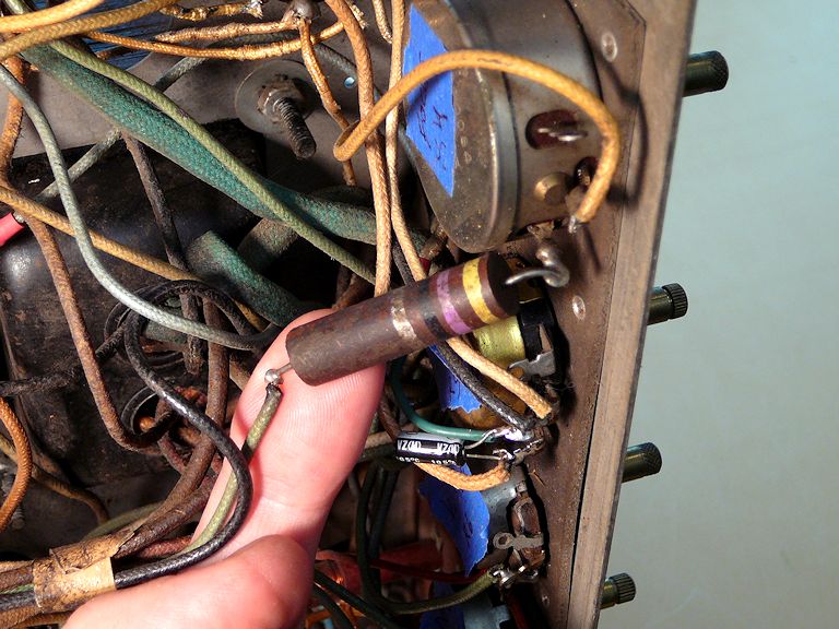
Replacing the Ballast
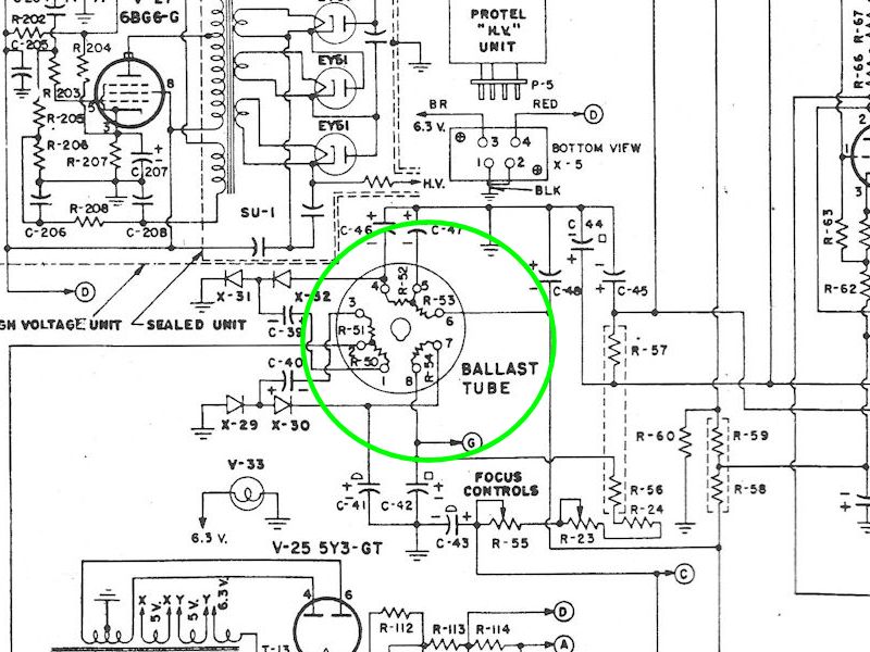
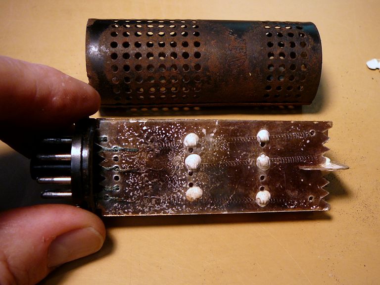
This TV uses a ballast in its power supply, as shown in the Riders schematic:

Although labeled there as a "ballast tube," this component has nothing in common with a tube
except its container. Inside the ventilated, tube-like envelope is an array of five power resistors, comprised
of thin resistive Nichrome wires strung on insulating mica sheets.


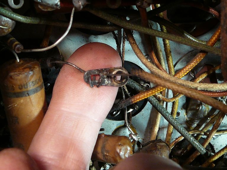
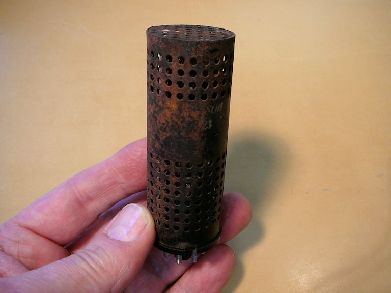
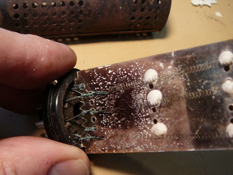
Testing the ballast revealed multiple failures and we can see that the connectors to the Nichrome elements
are badly corroded:

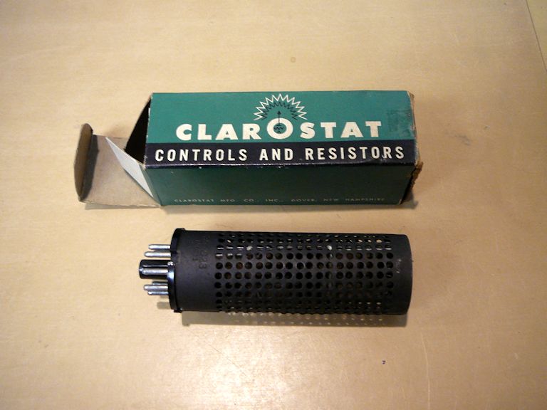
You can't easily attach new wires to the Nichrome elements, and after fiddling with this ballast for
a bit, I consigned it to the junk box and bought a new one from an eBay supplier. If you need to buy one,
the Emerson part number is 397023.

When new ballasts aren't available (and there are many different types), you can build a replacement
from scratch, as described in my Motorola VT-73 article.
Replacing Selenium Rectifiers
The power supply contains selenium rectifiers, which are notoriously
unreliable and emit a horrible stench when they fail.
(Selenium is also a toxic substance, as we learned in the 1999 movie Lethal Vows,
where an early incarnation of Phil's Old Radios website played a cameo role. That made a good story,
but outside of Hollywood drama, I have never heard of anyone being sickened by a selenium rectifier.)
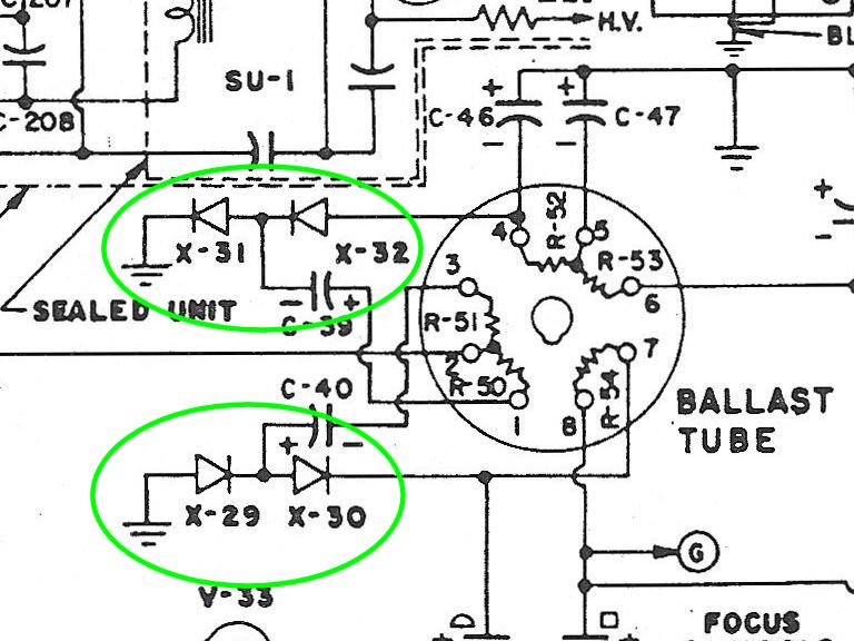
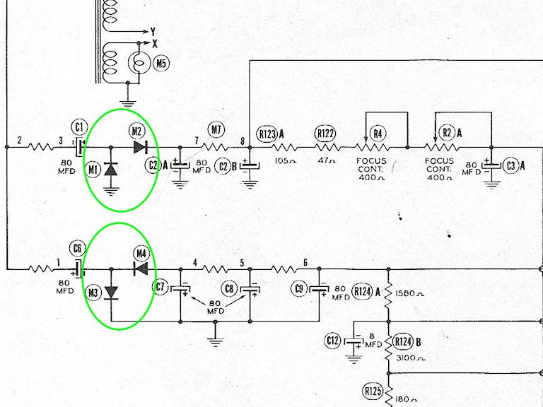
Reliability is important, so out with the bad (old selenium) and in with the good (modern silicon). This schematic
snip shows the 609's four seleniums, labeled X29-X31:

While we're looking at diagrams, notice how the Sams schematic draws these rectifiers and the ballast
somewhat differently, and compare that style to the Riders version in the previous snippet:

To me, the Sams portrayal makes it easier to tell at a glance what role the rectifiers play
in the overall circuit. On the other hand, the Riders drawing of the ballast shows more clearly
that the ballast is simply five resistors in a circular container. In Sams, the ballast is labeled as part M7 and
its components are identified as unlabeled resistors strung out to the left and right of the rectifiers,
between the ballast pin numbers (2-3, 7-8, and so on). Drawing style does matter when reading
schematics, and that's why I recommend using both manuals.
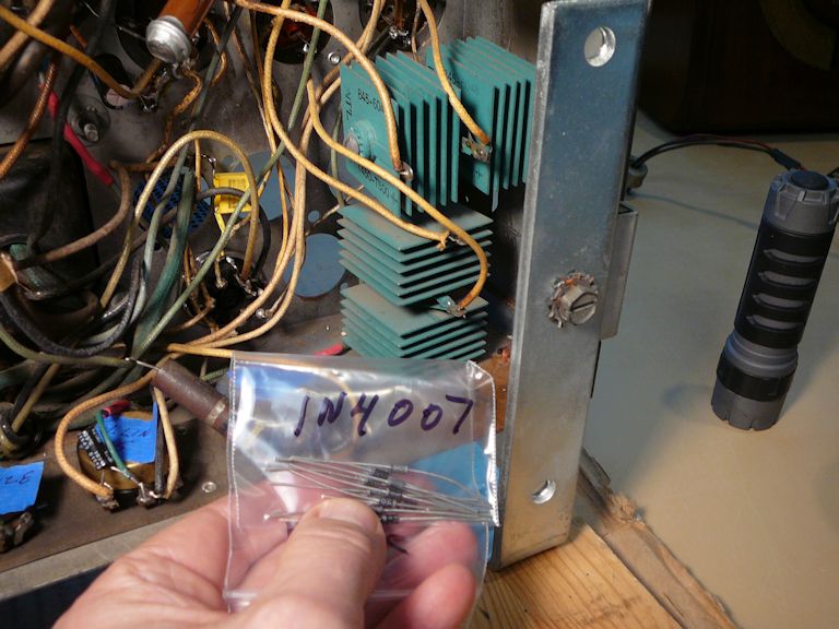
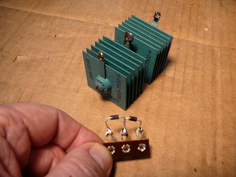
In the following photos, the old rectifiers are the big green finned objects. I replaced them
with tiny 1N4007 silicon diodes mounted on terminal strips.


Later in the project, after the TV was running, I added a power resistor in series with
each diode pair, to drop their output voltage to what's given in the manuals. This compensation is
often necessary because the new diodes have lower forward resistance than the old seleniums.
First Power
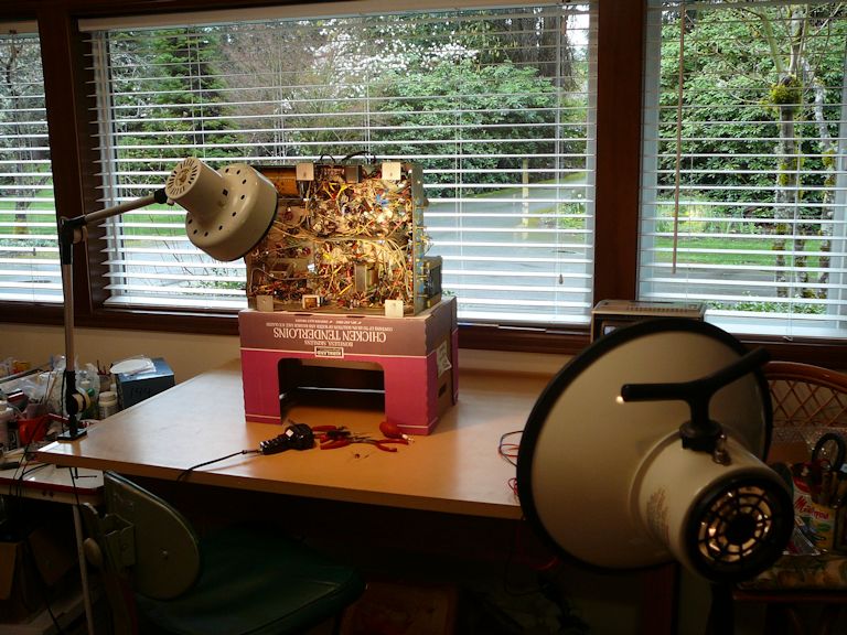
After hours of work, I'm ready to try the TV under power. The next photo shows the setup for
doing basic voltage checks:

The round black device to the right of the main chassis is my Powerstat 7.5-amp
variac, used to set the line voltage to 117 volts as
spec'd in the manuals. I don't expect much in the way of picture or audio at this stage,
but I have connected an antenna and test speaker just in case. (The antenna allows the
TV to receive signals from my in-home
TV transmitter.)
Within a few minutes, I confirmed that the TV's operating voltages were all in the
right ballpark. Even better, I got good audio and a bit of light on
the CRT.
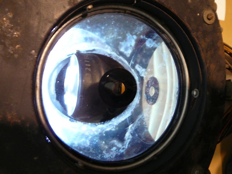
I can't view a full-size image with this workbench setup, since the big mirror and display screen
are still installed in the cabinet, but I can peer down into the optical box
and view the miniature picture tube directly. What I saw was a dark screen with the telltale
bright horizontal line caused by a failure in the vertical sweep circuits.

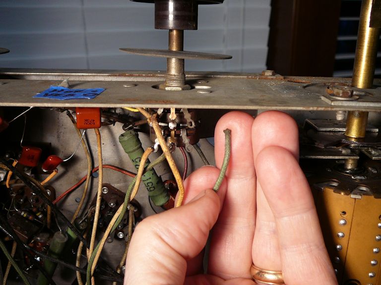
Diagnosing this problem took about 30 seconds. Looking first for obvious causes, I found that
a long dangling wire to the vertical hold control had been flexed one time too many, and simply fallen
off. Yes, this wire is one of the many flyaway leads that I complained about earlier in this
article, subject to being pushed or pulled at various places over its length. It took only moments to
resolder the lead to the vertical control:


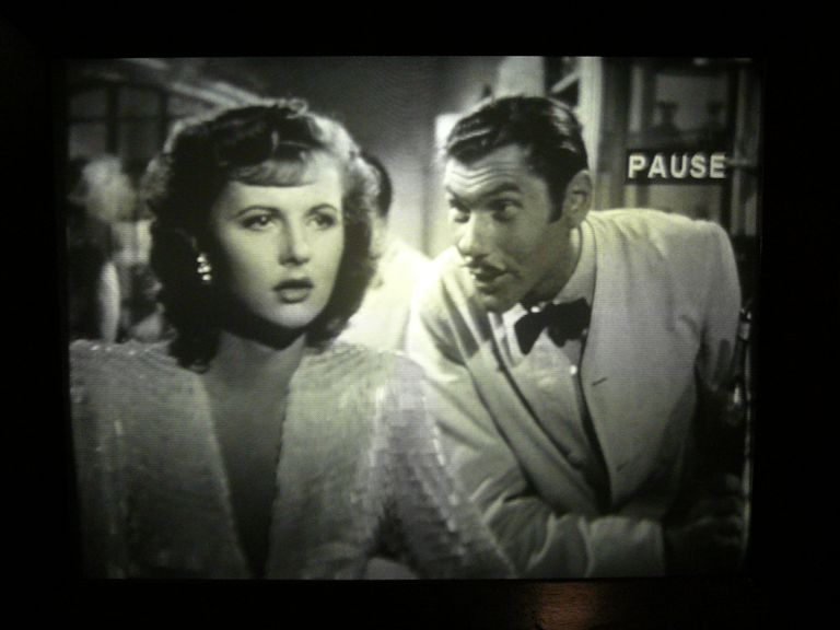
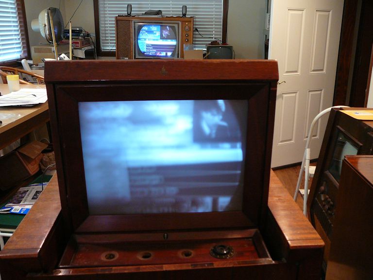
First Image!
I was rewarded with a genuine image—the very first I have seen on this television!
In the zoomed second photo, perhaps you'll recognize the familiar Xfinity cable TV guide
(in this trial run, I'm using rabbit ears to receive an "over the air" signal from my
home TV transmitter):

My camera can't focus well through the thick corrector lens on top of the optical
box, but the image was crisp to my eye. The horizontal and vertical hold was stable,
and the brightness and contrast controls worked as expected. I could
even hear nice audio through my test speaker.
Much work remains, but my hours of labor have paid off, so far.
The electronics are working, from front to back. I don't know yet if the optical
system will produce a correct image on the big screen, but the omens are favorable.
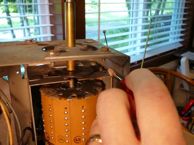
Tuner Cleaning
While changing channels during that trial, I noticed the telltale scratching that means
dirty tuner contacts. Although turret tuners are reliable, their contacts can oxidize or
collect grime like anything else.
You can clean the contacts on the barrel without removing it, and sometimes
that is enough to clear up a tuner. For a more thorough job,
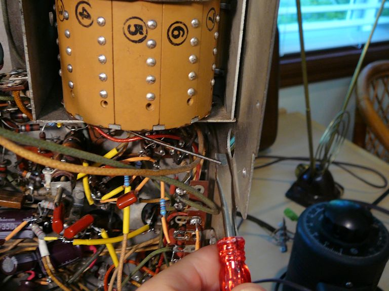
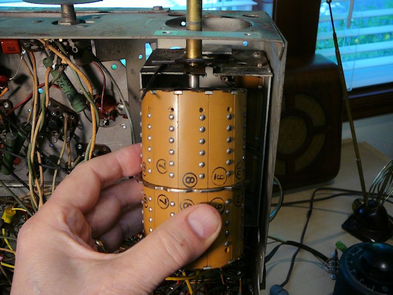
you also need to reach the contacts inside the tuner frame. Removing
the turret means releasing two stiff tension wires, one at each end of the tuner:


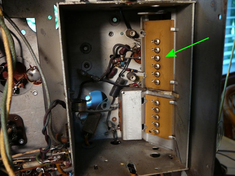
When the turret's out, I can clean this inner row of button contacts:

I also cleaned and lubricated the moving parts at the top and bottom of the rotating turret.
Now, all trace of static is gone, and this tuner should work smoothly for many years to come:

First Trial in the Cabinet
Time to get serious! Those positive results have me itching to reinstall the Protelgram
units in the cabinet and see something on the big display screen. The Protelgram boxes
need to be mounted in the right spots, of course, but the main chassis doesn't need
to be fully installed. Instead, I stood it behind the chassis and hooked up all
the cables, a method I have used in other projects like my
RCA CTC-4 color television:
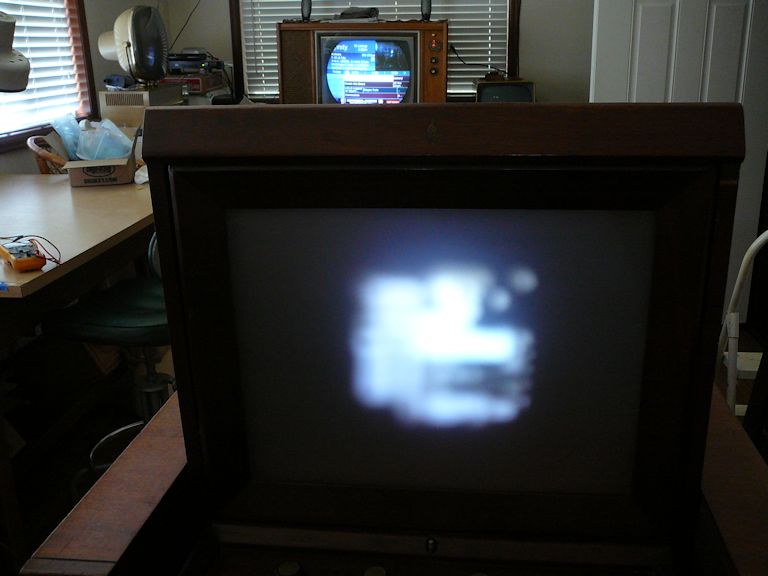
I dimmed the workshop lights, tuned the Emerson and a second TV to the same channel (broadcast by
my home TV transmitter), and saw the following. The first pic is
a still photo and the second is a two-frame animated GIF:

The Emerson makes a real picture—wahoo! Of course, it isn't perfect. The picture is
dim, even at maximum brightness, and I haven't done any focus adjustments (there are several), so
it's not crisp, either. And, although the horizontal hold control locks easily, there's some
horizontal jitter that contributes to the blurriness.
On the plus side, many things work well. The various controls, including brightness and contrast,
respond correctly. The picture fills the screen and has reasonable linearity. And the audio
quality is outstanding. The power supplies are stable and operational, even the 25-kilovolt HV supply
needed for the CRT to operate.
The electronics are alive and kicking. Now, I'll turn to the optical box, where I have
noticed a dodgy-looking mirror.
Resurfacing the 45-Degree Plane Mirror
The 45-degree plane what? Before I tear into my optical box, let's look at
a diagram and explanation of the Protelgram system, taken from the 1962 edition of
Television Simplified by Milton Kiver:
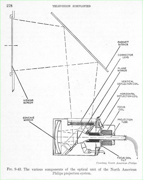
Another variation of the Schmidt optical system as adopted for television is that
devised by North American Philips. The system, known by the trade name "Protelgram,"
is an adaptation of the "folded" Schmidt system and occupies only half the space of
a conventional arrangement. Since the light path is folded, it is possible to mount
the projection tube with its optical system within a small metal box, thereby
producing a compact and dustproof arrangement. The actual metal case measures only
8½ by 8½ by 9 inches. It contains three optical elements: (1) a 6-inch spherical
mirror, (2) an aspherical correcting lens, and (3) a special plane mirror to "fold"
the light beam. See Figure 9-43. The light emitted from the face of the tube is
gathered by the spherical mirror, reflected to the plane mirror, and then projected
upward through the correcting lens. A throw distance of 32 inches from the
correcting lens to the viewing screen is required to produce an image 12 by 16 inches.

A special, small-sized cathode-ray projection tube (3NP4) was designed for this unit.
The diameter of the tube screen is 2.5 inches and a 1.4 by 1.86-inch picture is
obtained. It appears that 2.5 inches constitutes the smallest practical size from
which an enlarged image can be obtained. The tube uses magnetic deflection, magnetic
focusing, and 25,000 volts for acceleration. The spot diameter at the tube face is
0.003 inches, which permits a 450-line resolution to be obtained. The high-voltage
anode terminal consists of a button in a glass cup sealed to the cone of the tube.
The glass cup lengthens the external leakage path from the high-voltage contact
to the coils, thereby minimizing any tendency for arc-over to occur. The outside
of the cone and part of the neck are covered with a conductive coating that can be
grounded. This outer coating, together with the conductive coating inside the
tube, form a 300-mmf capacitor which can be utilized for filtering the high voltage.
Thanks for that summary, Milton! In this scheme, the picture tube's image is reflected
three times before passing through the translucent viewing screen and into your eyes.
If any of the three mirrors is dirty or degraded, the final image will be dim or blurry.
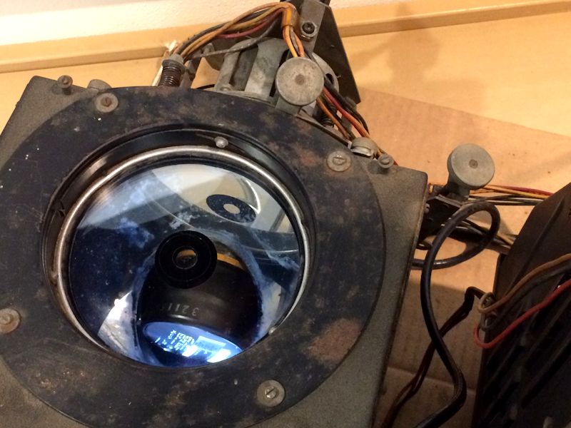
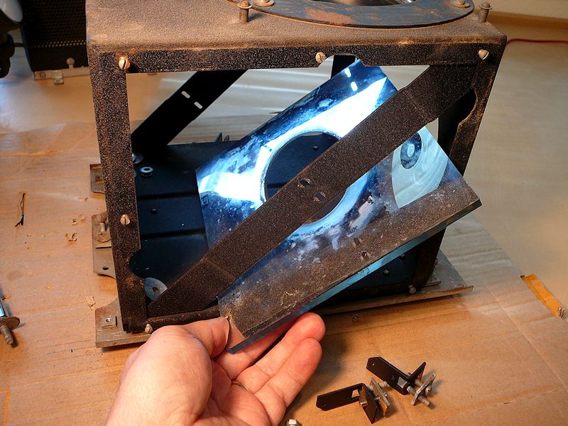
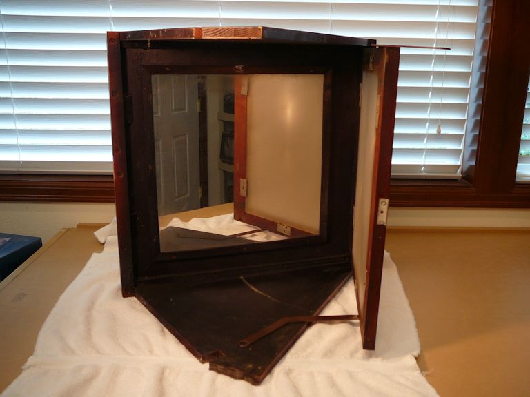
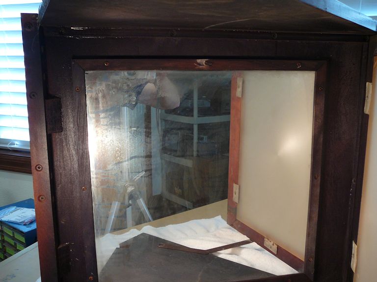
A peek into my optical box shows that my 45-degree plane mirror is defective. As noted
in the Protelgram diagram, the picture tube sticks out through a hole in this mirror:

This mirror was a known troublemaker even when the Emerson 609 was comparatively new.
Here's a service note from the Riders manual:
Discoloration of mirror used in the Optical Box on Projection
Receiver Model 609:

Due to the high voltage under which the kinescope anode in this unit
operates, a small amount of ozone is generated and in conjunction
with microscopic impurities in the mirror glass can result in
spotting of the 45° plane mirror.

In order to prevent this from happening, a simple procedure, which
consists of cleaning only, is recommended. This cleaning procedure,
if followed every six months, should prevent tarnishing and
discoloration.

The 3NP4 picture tube should be removed from the optical box and
the high voltage anode connector removed from the glass cup on the
tube. The inside of the glass cup should be cleaned thoroughly
with a brush saturated in carbon tetrachloride.
Okay, maybe ozone caused the damage to my mirror's surface.
In any case, the mirror needs help, so let's pull it from
the box and deal with it.
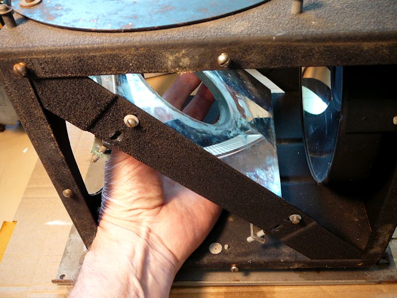
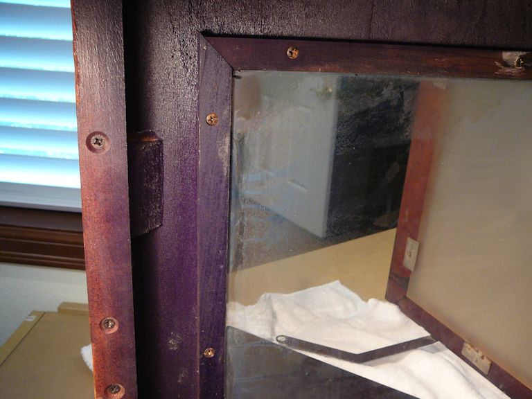
The first step in extracting the 45-degree mirror is to remove the side panels from the box:

Removing four nuts loosens the tailpiece assembly (including the CRT), which you may then
draw out through the rear of the box:
Pulling the tailpiece must be done with caution. It's easy to nick the fragile, beveled
edges of the plane mirror's hole by bonking the picture tube against them.
My mirror already has a few edge nicks, but they are confined to the beveled perimeter
that doesn't contribute to the projected image.
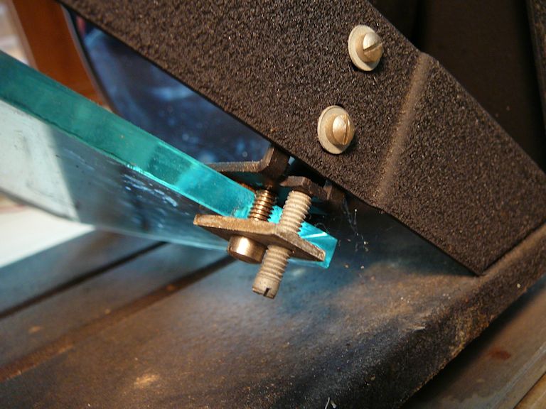
The plane mirror is held to the box struts by three side clamps; in the second photo,
I have begun to loosen them.


(In hindsight, I wish I had carefully marked which clamp belongs to each position on the
plane mirror, where along the mirror's side it was clamped, and how far down on the
slanted strut the two mounting screws for each clamp were positioned. The alignment of this
mirror at 45° is critical and once the mirror has been removed, it is tricky
to reinstall it correctly. Not only must the mirror lie back at exactly 45°, but it also must
not slant side-to-side.)
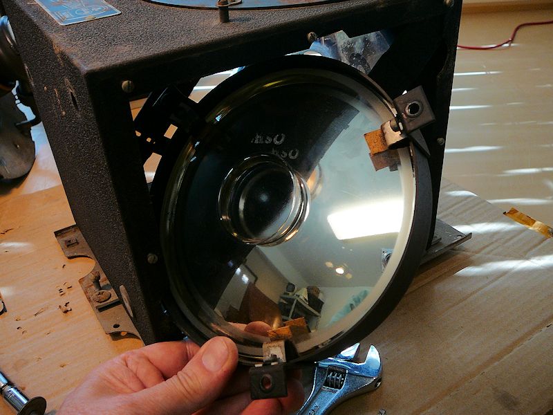
I thought the plane mirror could be extracted after removing its side clamps, but
that's impossible until you make more room by removing the spherical mirror, which mounts
on the back of the box.


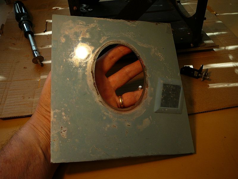
The spherical mirror in my Protelgram looks fine, so there's no reason to recoat it.

The plane mirror, however, clearly needs resilvering. (Resilvering is a slight misnomer, since
the reflective coating is aluminum.) Its reflective surface is discolored and
degraded—nearly transparent in some areas—and gentle cleaning didn't improve it a bit:

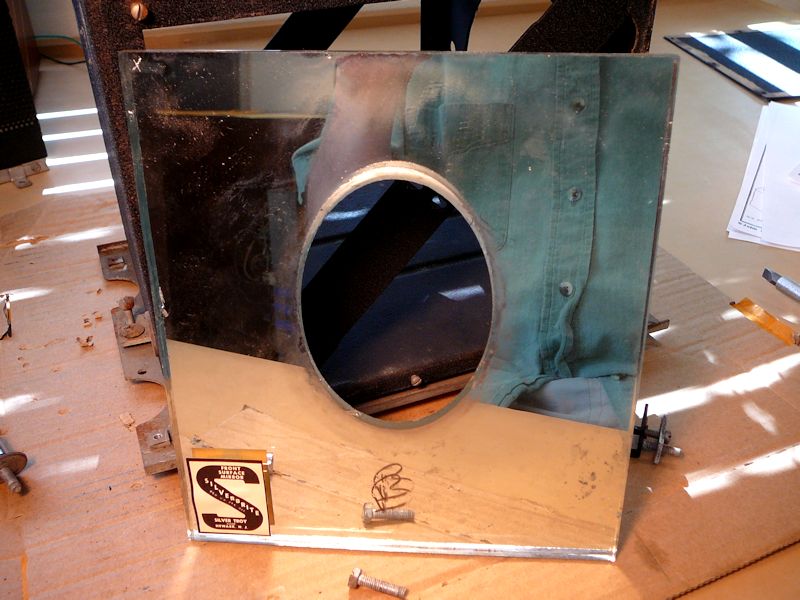
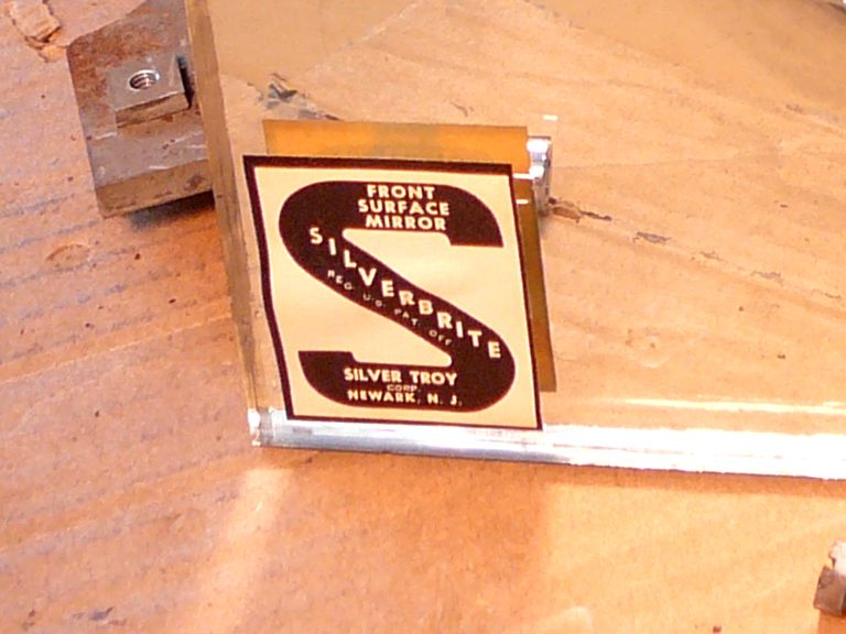
This is a "front-surface" mirror, like those used in telescopes. Its reflective
coating is on the front of the glass. An ordinary household or auto mirror
is a rear-surface mirror, whose reflective coating is viewed through (and protected by) a layer of glass.
When I turned this mirror over, its rear-surface reflection looked much better than the front.
A label identifies it as a Silverbright front-surface mirror, made by the Silver Troy company:


That might be handy for shaving, but I can't simply flip the mirror and use it
in the TV. Reversing a front-surface mirror makes it a rear-surface mirror and the intervening layer
of glass will refract the light beams and degrade the image. Moreover, the underlying
glass is probably not optically pure; the glass in a front-surface mirror isn't intended to be seen
through, only to provide a mechanical base for the reflective coating.
On the recommendation of a fellow collector, I sent my mirror to Spectrum Coatings
for recoating. Spectrum's main business is resurfacing astronomical telescope mirrors, but they handle other kinds, too.
Spectrum offers four different types of coating. When I enquired, they advised that
their least expensive Protected Aluminum (Quartz PAL) coating is appropriate for projection TVs.
The cost was just under $100, including shipping between Washington and Florida.
The turnaround for recoating is about 30 days, so I'll find other things to do in the meantime.
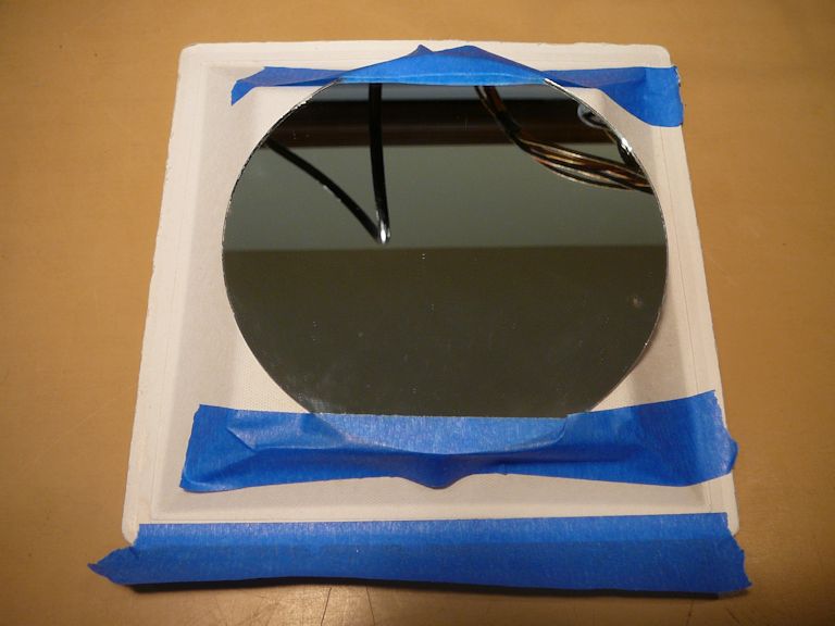
With one mirror missing, I can't display an image in the big screen. But I rigged a six-inch
mirror on a foam slab and taped it in the box at an angle that lets me peer inside as before,
getting a close view of the CRT's face:


Fixing the Horizontal
The last trial showed some horizontal jittering and I should be able to work on
this issue while the mirror is away being resilvered. I moved all three chassis back
onto the workbench and powered up the TV to investigate. Practically before my eyes, the
jittering got worse and then the horizontal hold collapsed, filling the screen
with a blizzard of slanted lines. No adjustment of the horizontal hold would
lock the picture.
At the same time, the vertical hold worked normally, indicating that the problem
was confined to the horizontal section, not originating from the sync section that feeds
the horizontal and vertical sections with their needed signals. (If the sync
section was malfunctioning, both horizontal and vertical would be affected.)
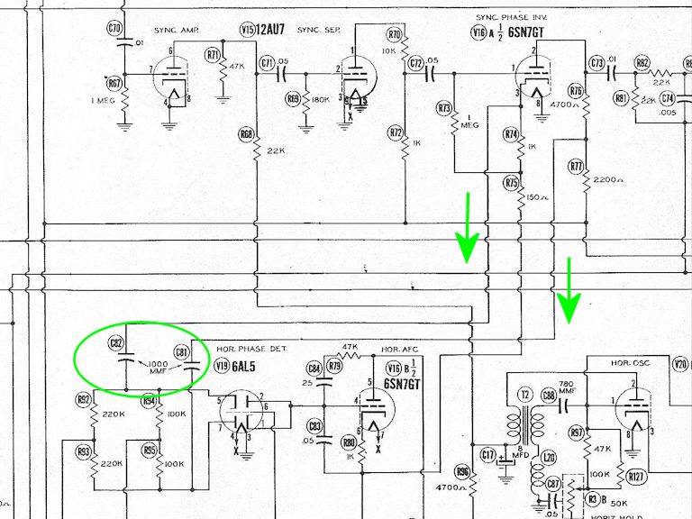
In the schematic, I identified two mica capacitors, labeled C81 and C82 in Sams,
which feed signals from the 6SN7GT sync phase inverter tube to the 6AL5 horizontal phase detector:

As noted earlier, mica caps can fail in the horizontal and sweep sections, where
they experience higher voltages and frequencies than in other circuits.
These two coupling caps are in a crowded spot, but with a little care, I can replace them:

Replacing the two little micas fixed the horizontal problem. Now, the horizontal
hold is stable, and it locks easily.
Reinstalling the Mirrors
The recoated 45-degree plane mirror has arrived, and its new surface looks brilliant!


Now I can reinstall the mirror in the optical box, hook up the chassis,
and try the full optical system again. In the next photo, I have removed the temporary
mirror that I used while the plane mirror was away. The recoated plane mirror sits
to its right.

The plane mirror must slide into the box sideways and then rotate to recline at a 45° angle:

It would be simpler to mount the clamps on the mirror before sliding it into the box, but
the opening is too cramped for that. I loosely installed the clamps after the mirror was inside:

Next, I remounted the tailpiece assembly with the CRT and adjusted the position of the plane
mirror so that the CRT was centered in the mirror's oval hole:

Now, the spherical mirror goes back in. It must be installed from this side of the
box, where a semicircular cutout in the frame lets you slip it in with only a whisker to spare:

Uff da! At last, the two mirrors are back where they belong, and the optical box is ready for another trial:

Removing and reinstalling these mirrors is a finicky process. I'm hoping that the system will still
focus properly after all of this in-and-out.
First Trial with the Resilvered Mirror
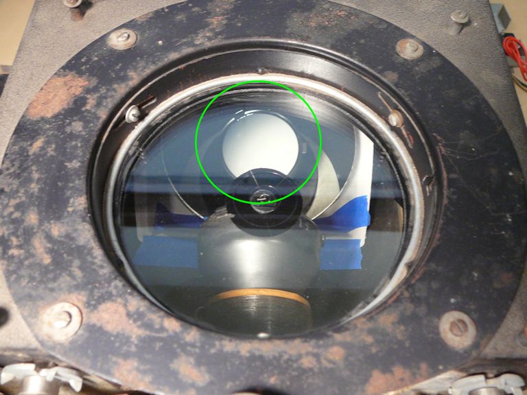
When I tried the TV with the new mirror in place, the result was disappointing. At first, the horizontal
centering was far off. When I adjusted that with the electronic centering control, one side of the image
was cut off by a semicircle—perhaps the edge of the corrector lens in the top of the optical box:

In addition to being cut off, the image has worse focus than ever.
I thought I had reinstalled the mirrors exactly as before, but clearly, something
(maybe more than one thing) is not right.
The Riders service manual is packed with information and diagrams about replacing and adjusting other
components in the Protelgram system, but silent about mirrors, which wouldn't be touched in ordinary service
except to brush off dust.
Losing and Regaining Deflection
While reviewing the schematics with focus in mind, I noticed resistor R122, attached to the lower
electronic focus control. (There are two electronic focus controls, one above in the user control
panel and another below in the set of service controls.). It's a 47-ohm, 2-watt resistor, attached with sloppy joints
that suggest is was a replacement:

The old resistor tests far over the specified value, so let's see whether replacing it
improves the focus. Not having a 47-ohm/2-watt resistor on hand, I improvised with two
100-ohm resistors in parallel, which made a 2-watt unit with about 49.5 ohms resistance,
well within the original 10% tolerance:

When I tried the TV again, the image looked worse than ever!

The image has shrunk to about half the normal size, with truly awful focus. Things have
gone from bad to worse! I don't see how replacing that resistor could cause this drastic effect.
A reduction in both horizontal and vertical deflection makes me wonder if something else has
failed, perhaps reducing the high-voltage output.
I'll try not to get too discouraged by this setback. Although the electronics seemed to be
working nicely before I resilvered the mirror, any newly-restored TV can suffer a relapse.
Sometimes a marginal component works for a while, but finally gives up the ghost
after running under normal voltage and heat conditions a bit longer.
I put out a call for advice in two vintage TV
forums, and was quickly advised to check for a
loss of B+ voltage, which could reduce both the horizontal and vertical deflection equally.
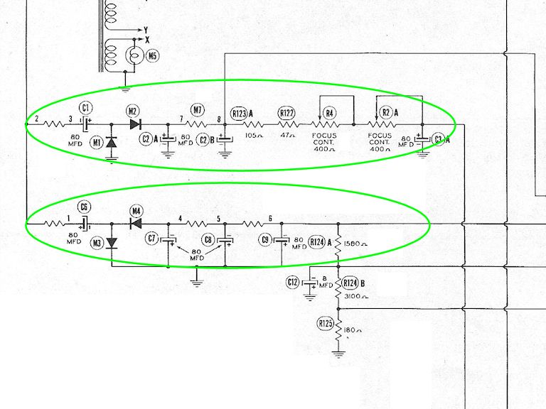
This TV has positive and negative B supplies, as shown in this schematic snip from Sams:

In these circuits, two pairs of selenium rectifier (M1/M2 and M3/M4) act as voltage doublers, one
producing positive and the other negative DC voltage.
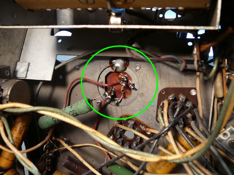
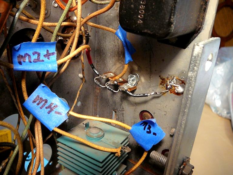
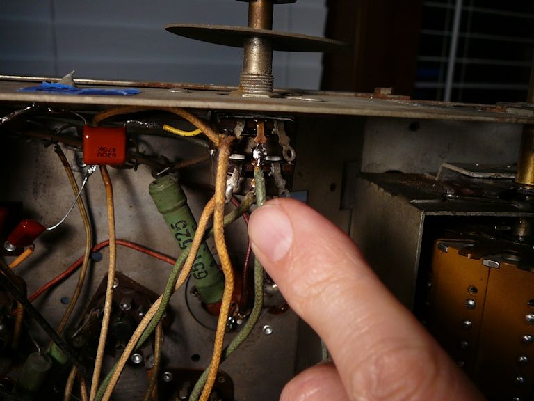
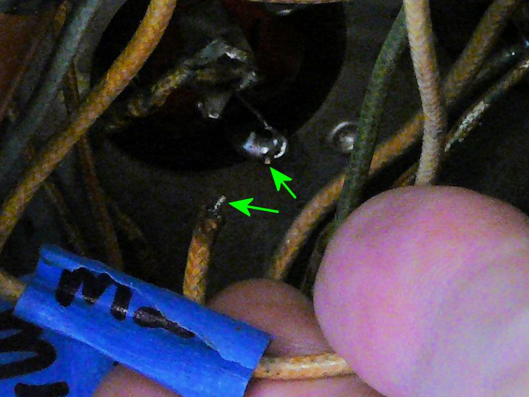
I began checking with my voltmeter along the first supply (M1/M2) and found normal voltages
everywhere. Turning to the other supply (M3/M4), I pushed obscuring leads out of the way to check
the junction of C6 and M3/M4, and the previously-hidden problem jumped out at me. Yes, it's
another broken wire, hidden in yet another dark corner:

Perhaps that lead was pushed or pulled when I muscled this awkward chassis back into
the cabinet. In any case, repairing the break should restore the B voltage and full deflection.
Resetting the Mirrors
Before trying the TV again, I opened the optical box and reset both the spherical mirror
and the 45-degree plane mirror.
Prior to the image collapsing, one side of it was cut off in an arc shape, by the edge of either
the spherical mirror or the corrector lens. The spherical mirror has no adjusters as such, and
I originally thought that it could only bolt into the box one way. But when I removed its screws
this time, I noticed that the mounting holes are larger than the screws, and the big washers used
on both sides of each hole seem to contemplate some adjustment:

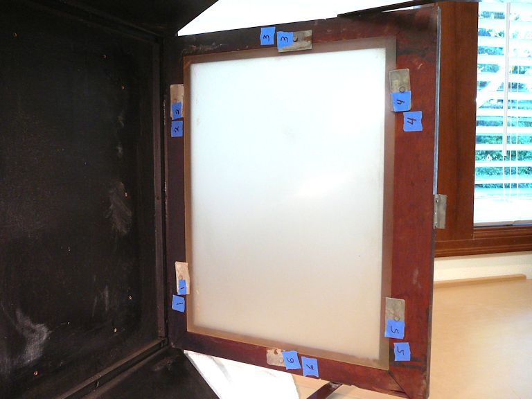
I marked the center of each mounting hole with tape tags and
reinstalled the spherical mirror with each screw dead-center in its hole. (Visualizing the
image path in my mind, I believe that the cut-off image was produced because the mirror
was mounted too low.) I also checked and adjusted the angle of the 45-degree plane mirror.
If that sounds like a crude method, you're right. When these Protelgram boxes were built by
Phillips, factory technicians used a special device to align the mirrors. This gadget substituted
for the 3NP4 picture tube (!) and had a test pattern printed on its face:
You can read more about this gizmo
at the Early Television website, which provided the previous photo.
I don't own one of these unobtainium alignment tools and trying to build one goes far above my pay grade,
so I crossed my fingers and did the best I could using rulers and tape marks.
When I retried the TV, I had full vertical and horizontal deflection; there was no arced
cutoff of the image; and, thanks to the recoated plane mirror, it was brighter than before:

The focus and screen geometry are still imperfect, but I'm back on track. (The animated
.GIF picture also shows what looks like blooming in the higher-contrast scene, which
might suggest poor high-voltage regulation, but I'll table that issue until I solve
the optical problems and obtain a focused image with normal geometry.)
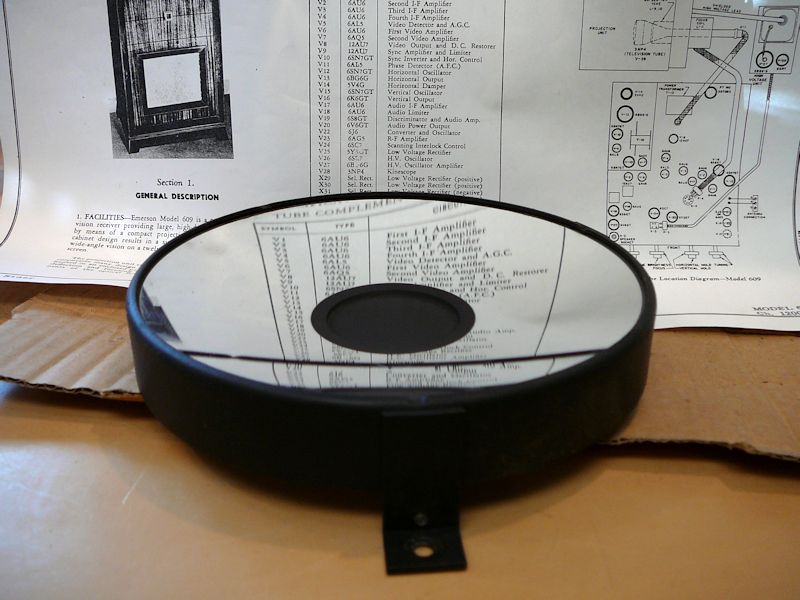
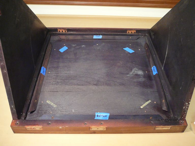
Removing the Display Canopy
While I had the optical box on the workbench, I took that opportunity to peer up into
the display canopy and inspect the big final mirror. As the Protelgram diagram
shows, this third mirror ("cabinet mirror") reflects the enlarged image onto
the screen.
I had hoped that the mirror's upside-down
position under the canopy would protect it, but its surface looks mottled and degraded, like the
plane mirror before recoating.
Removing the big mirror will mean detaching the whole canopy, and that reminds me
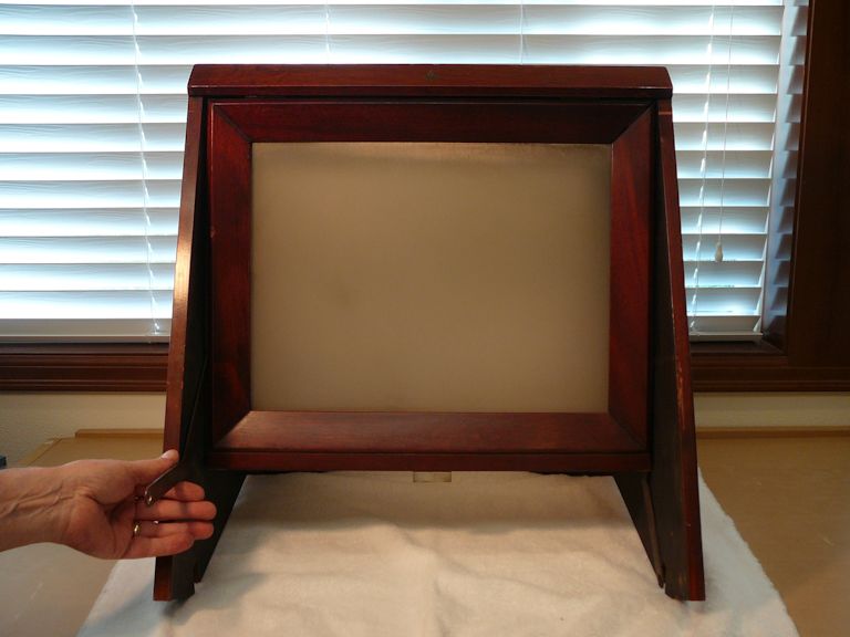
of something else I noticed earlier but didn't take very seriously. The wooden frame
holding the screen has open glue joints on one side, and the frame won't slide
forward all the way when you move the screen into locked position. In this photo, notice how
there's a larger gap on the right side, between the screen frame and the control panel frame:

Having the screen off-kilter prevents a smooth focus across the width of the image.
I need to repair the frame so that the canopy moves smoothly and locks in the right
position.
Removing the Display Canopy
Detaching the display canopy from the cabinet took longer than I expected.
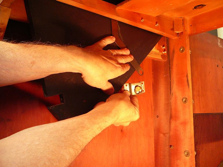
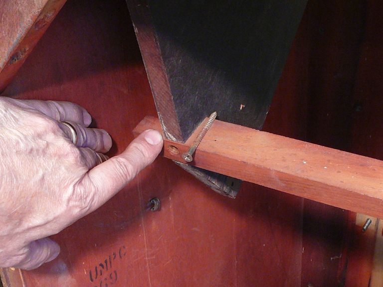
The screen frame folds down when you lower the canopy and it uses two metal struts,
one on each side. The struts are attached to metal brackets that are nigh impossible to reach until you
remove the chassis:


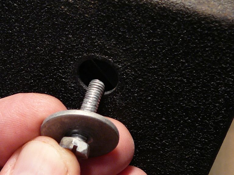
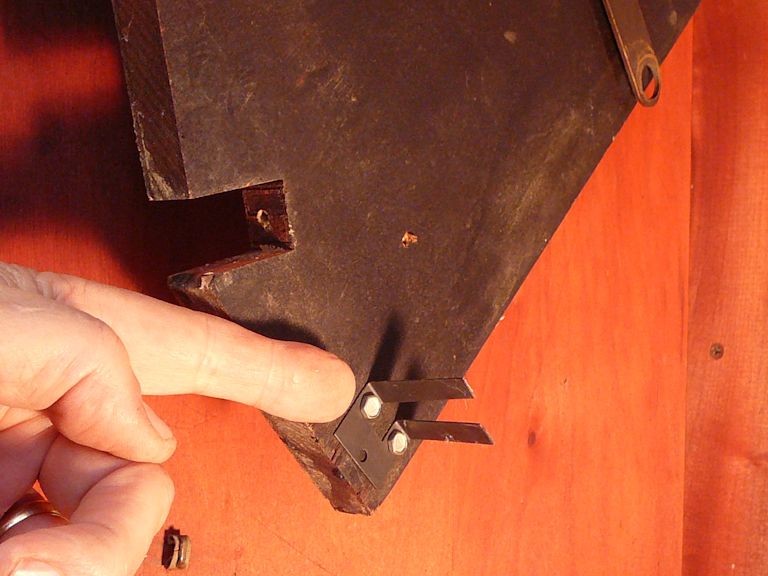
After unscrewing each bracket from the cabinet, I noticed that the brackets are held to the struts with
spring washers:

In hindsight, it would have been easier to remove the washers and leave the brackets
in place. I'm not the first guy to miss this, however. Two of the needed four wood screws were
missing from each bracket, indicating that a previous repairman lost half the screws or was
too lazy to replace them all. (Which made me wonder why those brackets were removed; the
big mirror and the screen were clearly original and untouched since leaving the factory. Did
somebody go to all the trouble of removing the canopy just to move the TV? Or did they start
taking everything apart and then give up?)
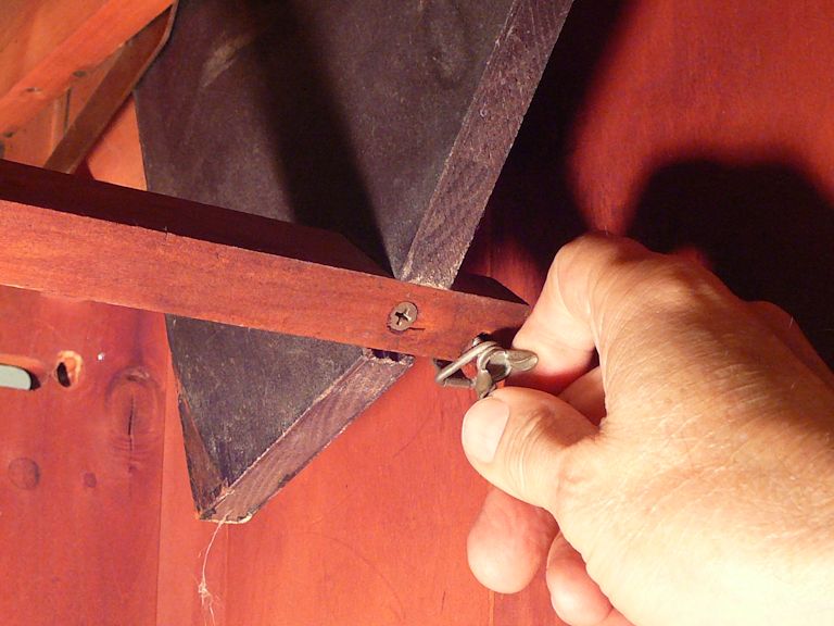
Each side of the canopy has a strong spring, attached to a steel tape that pulls down when you lower the cabinet.
This provides a balancing force when you lower the canopy, which could otherwise fall under
its own weight and smack the cabinet. Each spring attaches to the side piece
with a wing nut:

After detaching the counter-balance springs, you can remove the wood crossbar that goes between the two side
pieces:

You must also remove the metal stop that keeps the canopy from moving up too far when
raised:

At last, I could slide the unencumbered side pieces up through their slots and remove the canopy
from the cabinet body:

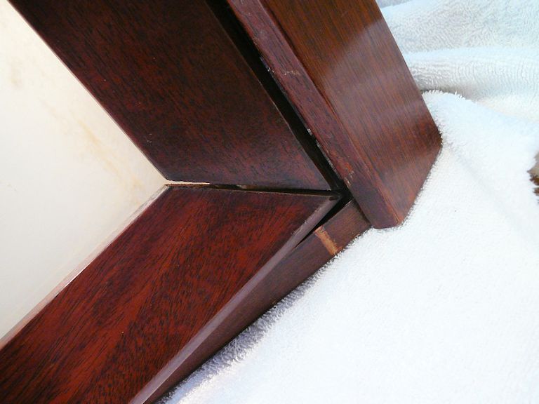
As noted earlier, the glue joints have popped loose on two of the screen frame corners:

From inside the canopy, I can see that that frame rail would simply fall out if it weren't held in place
by a screen mounting bracket.
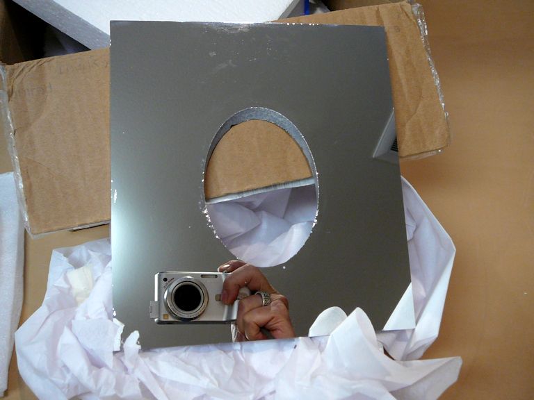
Resurfacing the Final Plane Mirror
Now I can get a close look at the big plane mirror. It doesn't look bad from a distance, but its surface
is seriously compromised, just like the 45° plane mirror:


The schmutz in that second photo is degraded reflective coating, not mere dirt. Cleaning
the mirror didn't change it a bit.
The heavy mirror is 15" square. It is mounted with four wooden rails screwed into
the canopy's top:


The reverse side has the same Silverbrite label as the 45° plane mirror:

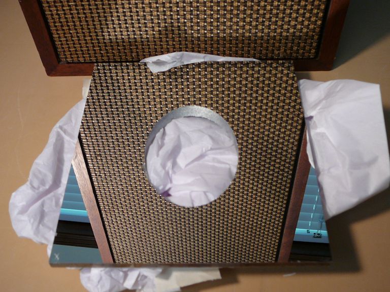
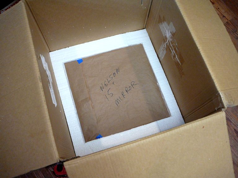
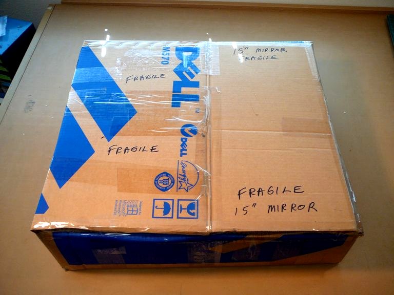
I packed the mirror according to
Spectrum's instructions, surrounding it with
layers of rigid styrofoam. The heavy cardboard box was cut down to fit:


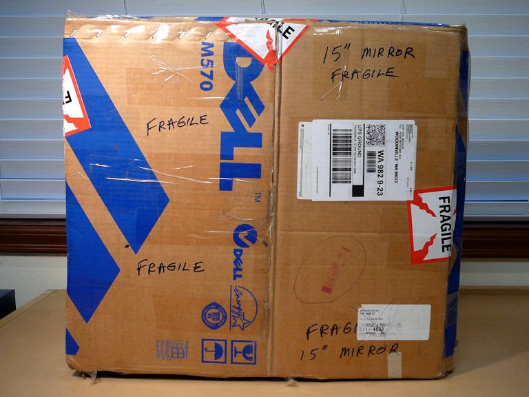
A few weeks later, the package returned, having traveled from Washington to Florida and
back again. I unpacked the recoated mirror with great anticipation. Thanks to careful packing,
it's still in one piece.


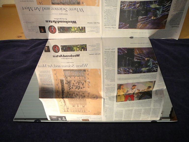
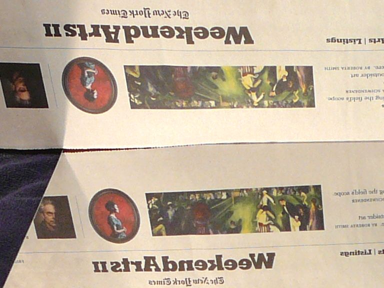
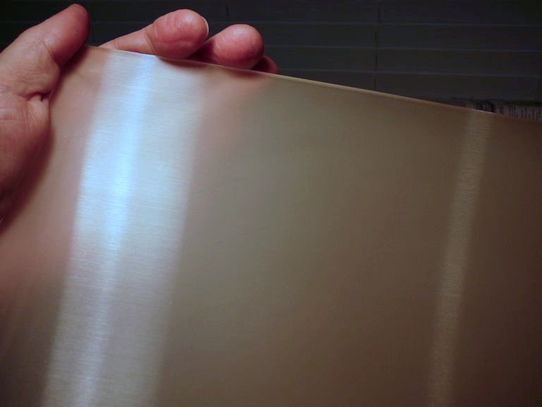
The recoated mirror is quite beautiful. I photographed it lying on a black towel,
with a sheet of newspaper providing something to reflect.


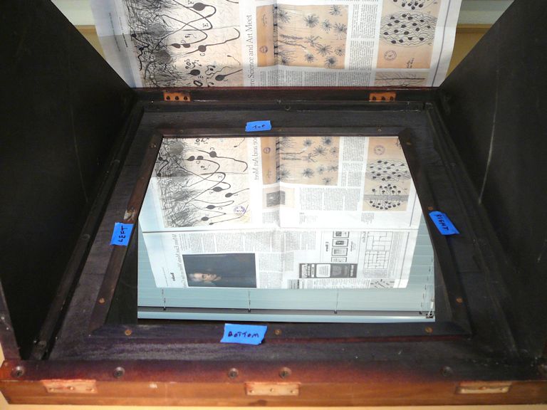
Cleaning the Projection Screen
The other optical component in the display canopy is the front projection screen. My screen isn't
damaged, but it needs cleaning. It's not obvious in these photos, but the screen has a
brownish-grey halo of dirt around its edges, probably the usual household grime.
In the first photo, the canopy is lying on its side, after I removed the big mirror.


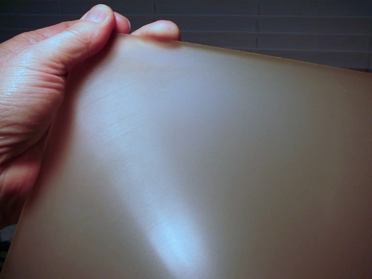
The screen is made of translucent plastic, with different textures on its front
and rear surfaces. The front has a circular pattern of very fine concentric lines, which look like they
were stamped in:


The rear surface of the screen is textured with horizontal lines that are finer and less
regular than the concentric lines. They might have been made by gently wiping very fine sandpaper or steel wool
across the rear:


Emerson went to some trouble to apply this combination of screen textures running in different directions.
I wonder what they had in mind? Of course, the screen must be translucent rather than
transparent; otherwise, the projected image would simply pass through it and shine on the wall.
And, you want the screen front to have a non-glossy surface, to reduce glare from other light
sources. Beyond that, I'm not sure.
Once the screen was out, it was easy to clean off the dirty halo with a soft sponge
and warm soapy water. I would recommend against trying to polish the screen in any way.
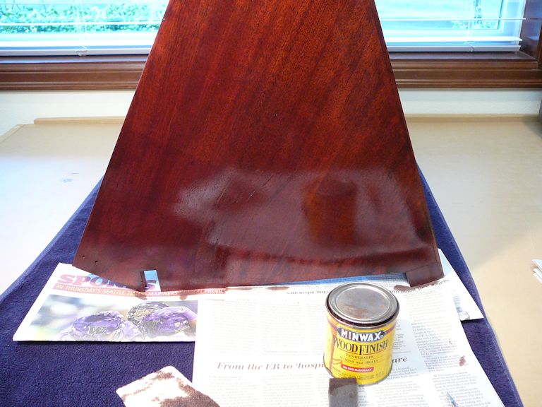
Refinishing the Cabinet . . . or Not
Now seemed like a good time to refinish the cabinet, since I had completely
emptied it, and it would take a few weeks for my mirror to be resilvered.
I brought it to a friend who had refinished several other cabinets for me.
A couple of days after I dropped it off, I got a message from my friend, who had
injured his shoulder and was scheduled for arthroscopic surgery. That would mean
no lifting of heavy objects like TV cabinets for a minimum of three months!
To avoid stalling the project, I brought the cabinet back home. The TV screen can't
be viewed at all until the TV is fully assembled, and this way I can make
progress on the electronics and optics while waiting for the refinisher to heal up.
Reinstalling the Screen and Final Mirror
I have the canopy on my workbench, ready to reinstall the screen and mirror. It's
a convenient time to touch up these scratches on its sides:


The scratches must have occurred when the screen frame was out of plumb and the
canopy couldn't go smoothly up and down. They are mostly hidden when the cabinet is
reassembled, but they bugged me just the same, and touching them up took only a few minutes.
Before installing the optics, I gave the inside of the wooden canopy a good scrub-down. I don't want
it to shed any dust or fluff near the mirror and projection screen. Reinstalling the mirror is easy; you
lay it face-up in the upside-down canopy and screw down the four mounting rails.


Reinstalling the screen is trickier because there's little clearance to get a screwdriver into
the right place, but the job is soon done:

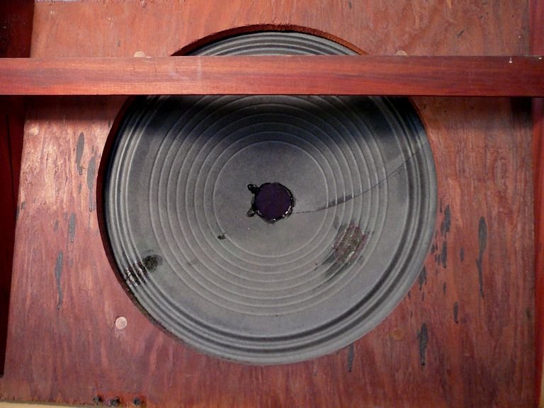
Repairing the Speaker Cone
While the cabinet's empty, I may as well repair these minor boo-boos in the speaker. The cone has a couple of tears and
it is missing the round fabric cover for the voice coil. Tears are easy to fix with flexible
glue and some tea bag paper. The dust cover is a circle of very thin fabric glued over the hole.


If you tear the edges of your tea-bag paper, rather than cut them, they will feather nicely
onto the cone material when glued. You can color the repair with a black marker or paint
if you like, although the speaker will sound the same, regardless.
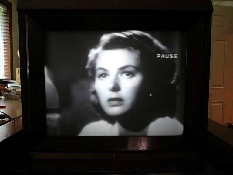
First Picture After Reassembly
It's a long time since I saw an image on this TV's screen, and I'm extremely curious to
see how it looks with resilvered mirrors. After a few adjustments, I saw this:

This image is much better than previous ones. Although not super bright, it has decent
contrast and focus. The horizontal linearity is poor, however. Sam the
piano player's head is stretched laterally into a mutant shape!
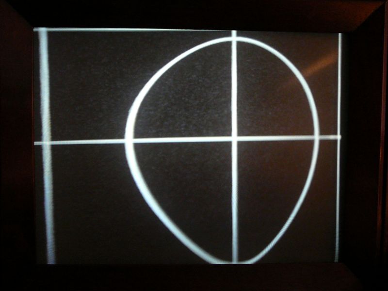
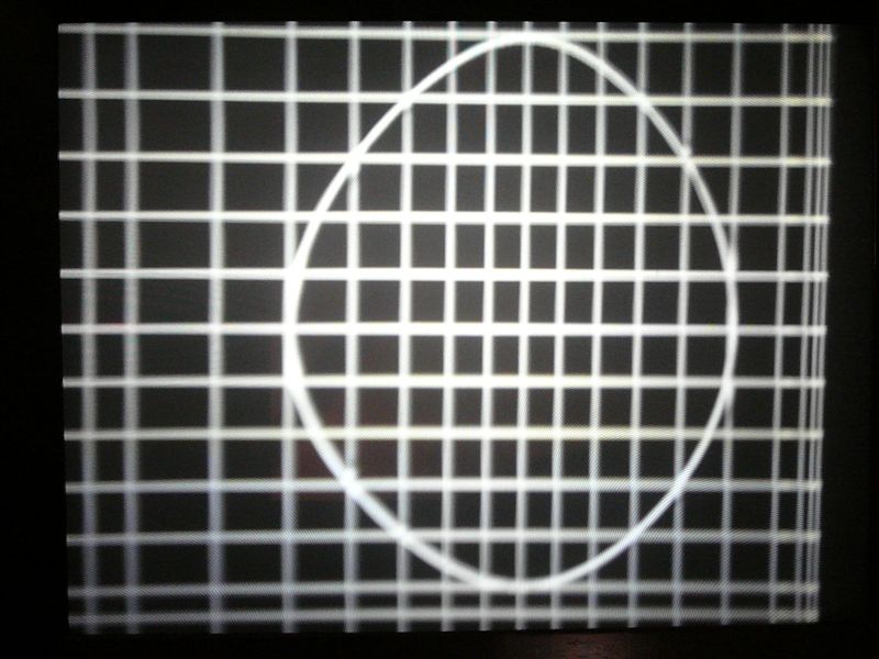
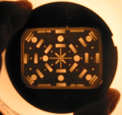
Displaying a test pattern shows that the vertical linearity is also deficient, although
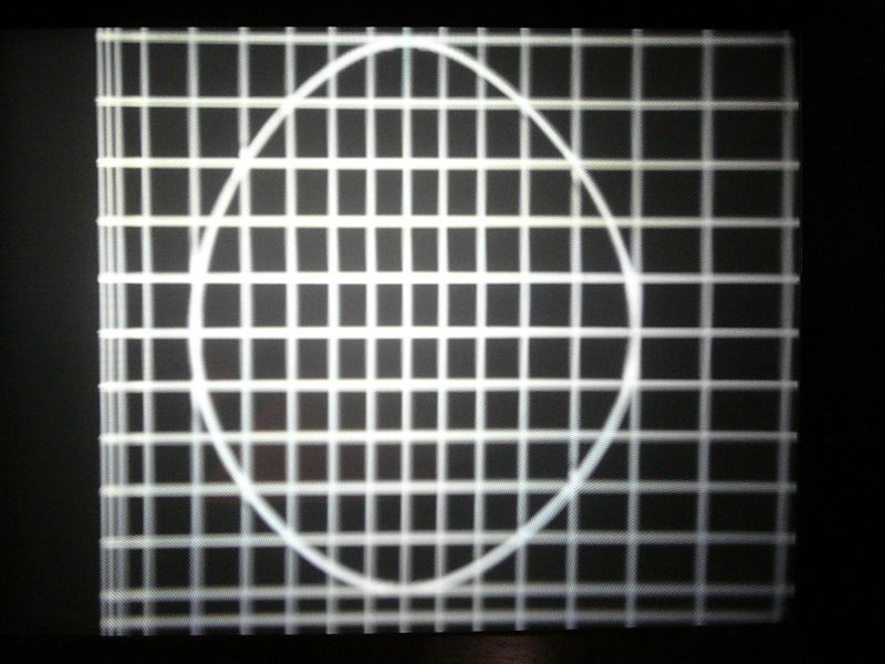
not as bad as the horizontal:

This pattern should show a circle, centered on the screen, with a crossing line through its middle.
Instead, the central cross is far off center, and the circle is a peculiar egg shape.
No combination of adjustments to the linearity, width, and height controls improved
the situation; I could make the pattern worse in various ways, but not better! And the best
pattern was achieved by cranking the width and horizontal linearity controls nearly to
the ends of their ranges, a sign that the electronics are faulty, not merely out
of adjustment.
Pulling the Chassis—Again!
When the chassis is in the cabinet, you can access many under-chassis areas through the
cutout hole in the wooden sub-frame. Unfortunately, the circuits I need to test now are
crammed into the edges of the chassis, hidden behind the sub-frame borders.
Grrrr! I pulled the chassis—again—and brought it back to the workbench:

I had already replaced many capacitors in the sweep circuits, and now I checked all
their resistors and mica capacitors, in search of possible culprits. No smoking guns
appeared, although I did replace a couple of micas and out-of-tolerance resistors
along the way, more for reliability's sake than in hope of a cure.
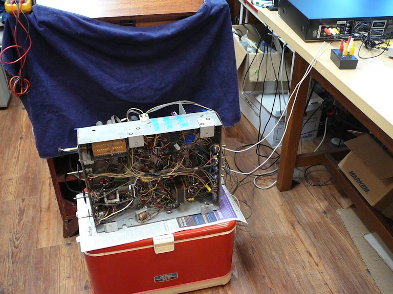
To try the set again, I stood the chassis behind the cabinet and hooked it up:

If you look closely, you'll see the TV's screen reflected in my little serviceman's mirror,
which stands in front of the cabinet. If I place that mirror in exactly the right spot, and
crane my neck, I can watch the screen while adjusting from behind the cabinet.
This setup relieves me of the chore of reinstalling this heavy chassis in the cabinet every
time I want to test some little electronic change. And it frees the chassis for
access with an oscilloscope and other test instruments.
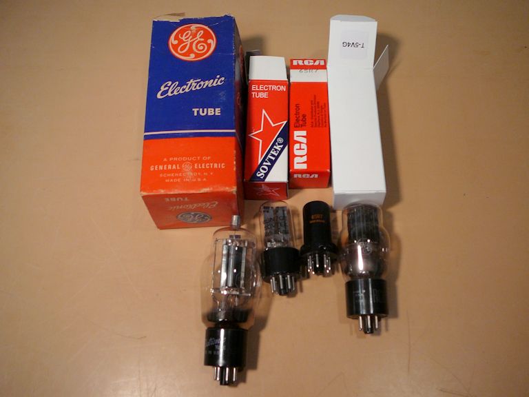
The latest component changes didn't cure the linearity problems, but I can cross
a few more parts off the questionable list. I also installed four new tubes (although the
originals had tested OK): the horizontal output (6BG6), horizontal oscillator/discharge (6SN7),
high-voltage oscillator (6SR7), and damper (5V4G).

Tube testers can't test oscillation,
so an oscillator tube that tests "good" for emissions may nevertheless fail to
oscillate correctly. Swapping in new tubes didn't cure the linearity issue, but it gave me
confidence that the problem wasn't caused by an oddball tube defect.
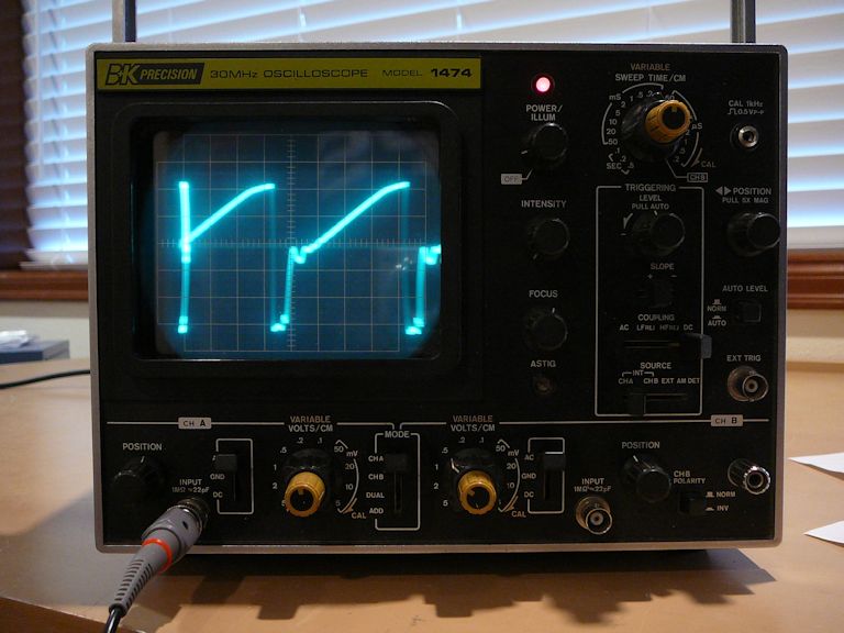
An oscilloscope can be handy in diagnosing sweep troubles, but the Emerson 609 manuals have very
few example waveforms for comparison. The Sams manual has none, and the Riders
manual offers only a handful. When I scoped likely spots, I didn't see anything gravely suspicious.
Here's one of the horizontal waveforms, which approximates the model given in Riders:

Optics vs. Electronics?
Now, a question arose in my mind. I hadn't found anything seriously
defective in the sweep circuits, but what if the optics—not the electronics—were
causing this distortion? I don't have good photos to show it, but while
adjusting linearity and other controls, I had observed strange effects unlike what I had
seen in other TVs.
At this point, I had removed and reinstalled all three of the TV's mirrors. The big mirror in the canopy
isn't troublesome—it can only be installed one way—but things are tricky inside the Protelgram
optical box, with complicated relationships between the small plane mirror, spherical mirror, and corrector
lens. I was able to reset the spherical mirror to eliminate a gross misalignment, but I had to do that
without the special alignment tool used at the Phillips factory.
What if some subtle optical misalignment is causing only part (or parts) of the final image to be stretched?
In other words, what if the electronics are producing a perfectly linear image, but that image
is being distorted somewhere along the optical path?
The mirrors inside the box are not designed to be adjusted in real time while
observing results on the screen, so I felt stymied until I mentioned the issue
in the VideoKarma forum.
Fellow collector Josef, from Austria, suggested an easy test: reversing the horizontal
wires in the picture tube's deflection yoke. Swapping those two wires will flip the displayed image horizontally.
If the distortion (horizontal non-linearity) is also reversed, then the problem lies in the
electronics, not the optics. If the distortion remains the same after reversing the wires,
the problem lies in the optics.
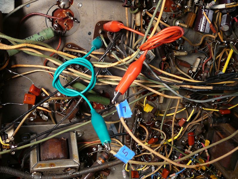
In the following schematic, reversing the horizontal yoke wires means swapping connections to pins
5 and 7 at the connector shown in the lower right:

In this photo, I have unsoldered the wires from yoke connector pins 5 and 7 and attached them to clip leads
for easy reversal while I view the results on the screen:

This simple and elegant test answered the question immediately. My problem is in the electronics, not
the optics. The next two photos show the test pattern with normal connections and then with reversed
horizontal yoke connections:


In the first photo, the squares are stretched in the left part of the screen and bunched on
the right. The second image is bunched at the left and stretched on the right—exactly
reversed.
Thanks, Josef! I will suspend judgment about optical issues and seek an electronic solution.
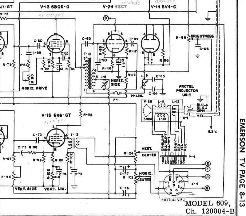
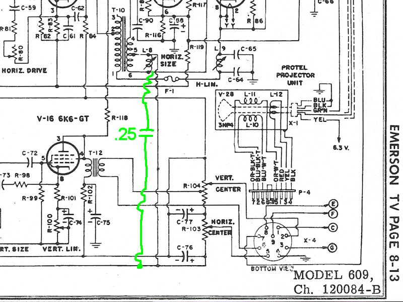
Replacing the Damper Filter Resistor
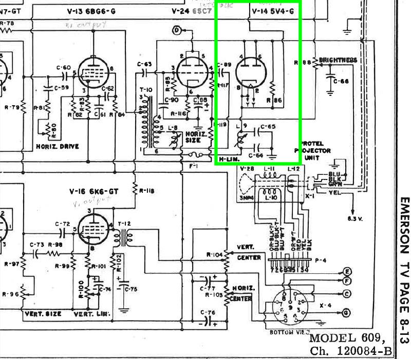
The horizontal linearity adjuster is part of the damper tube circuit, which is highlighted
in the following schematic:

In the diagram, tube V-14 is the damper, located downstream of the flyback transformer T-10.
Coil L9 is the horizontal linearity (H-LIN) adjuster, and L9 is flanked by two filter
capacitors, C64 (.035 mfd) and C-65 (.05 mfd). Another damper filter is R86,
a hefty 25-watt wire wound resistor.
I had already replaced C-64 and C-65, along with other paper capacitors, but I disconnected
them and checked them on the remote chance that one of the new caps was defective. Finding nothing amiss,
I reconnected them.
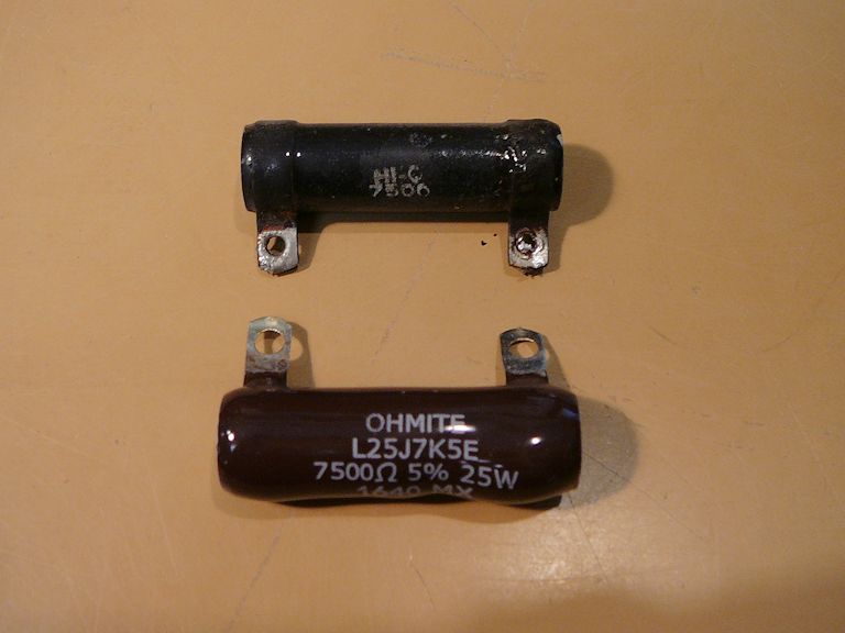
Resistor R-86 is mounted inside the high voltage cage and I had overlooked it in previous
resistor checks. When I loosened the mounting bolt and disconnected one lead for
testing, I found that it was open. Aha! Luckily, I was able to find a replacement that
fits the original mounting hardware.


Replacing that resistor cured the worst non-linearity, but now the screen width was too narrow! Even
with the horizontal size adjuster set to its maximum, the image couldn't fill the screen laterally.
Increasing the Screen Width
Much earlier, during the initial recapping phase, I had found and removed an old modification:
a 0.25-mfd capacitor crudely wired in parallel with the width coil:


I removed this capacitor because slapdash mods like this are sometimes
band-aids whose need goes away after you thoroughly restore the electronics.
However, the effect of adding capacitance across a width coil is to increase
the screen size—just what I need, now that I have gotten the TV working.
Evidently, that old modification was there for a reason!
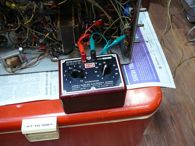
I hooked up the chassis in the cabinet and used a capacitor substitution box to experiment with adding
capacitance of different values across the width coil (0.1 mfd, 0.2, 0.3, etc.):

The width grew slightly with each capacitance increase, up to about 0.3 mfd, where the width began to
decrease again. I settled on 0.22 mfd as the best value.
After replacing the damper resistor and adding a capacitor across the width coil, I
have a watchable picture with approximately correct screen geometry:

The electronics need more tweaking and the cabinet needs refinishing, but for
the first time, this TV has reached a state where I can sit down and enjoy
watching a full program.
Injecting Video and Audio Signals
After watching real program content for a while, I decided to try injecting video and audio signals.
The picture wasn't quite a crisp as I'd like, and I wanted to find out whether the lack
of detail was due to insufficient bandwidth in the TV's tuner and IF sections or to some maladjustment in the optical system.
By injecting video and audio signals directly into the video and audio amplifiers, you can bypass
the tuner and IF stages, eliminating any issues (such as misalignment) that may degrade the
output from those upstream stages.
Injection is usually a simple matter in old black and white TVs. In another article,
I described building an A/V adapter for my Admiral 24C15 set. The
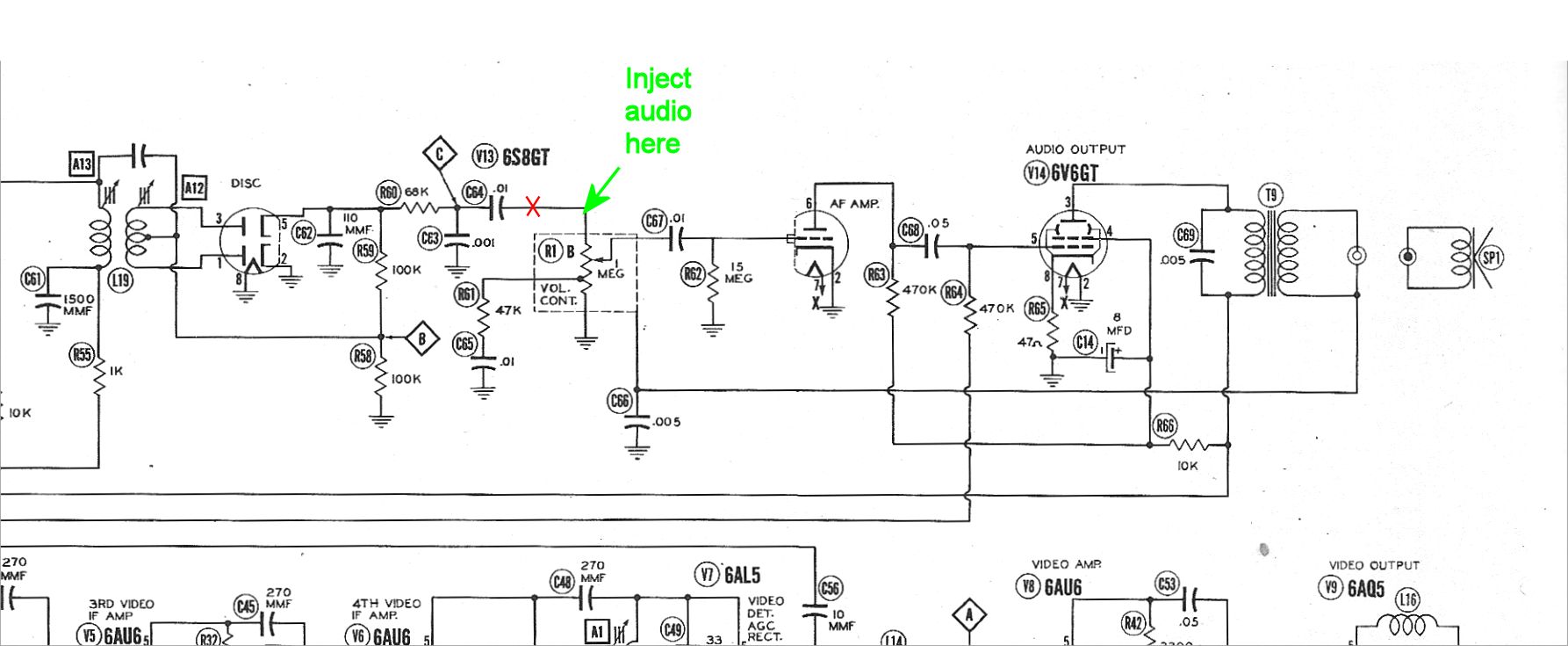
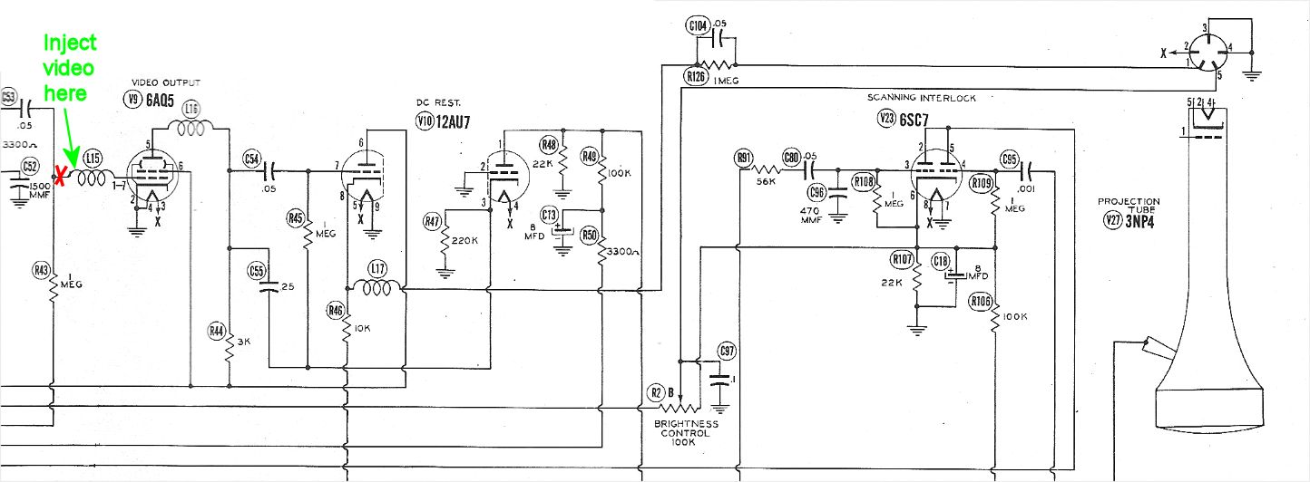
technique was very similar for this Emerson. The following diagrams show the signal insertion points.
For the audio, you disconnect the output from the 6S8GT discriminator tube (V13A) and connect the external
audio output at the upstream leg of the Volume control (R1B), leading to the input grid of the
first audio amplifier (V13B):
For the video, you disconnect the output
from the video detector and connect the external video output at the upstream end of peaking coil L15,
leading to the input grid of the video output tube (V9):
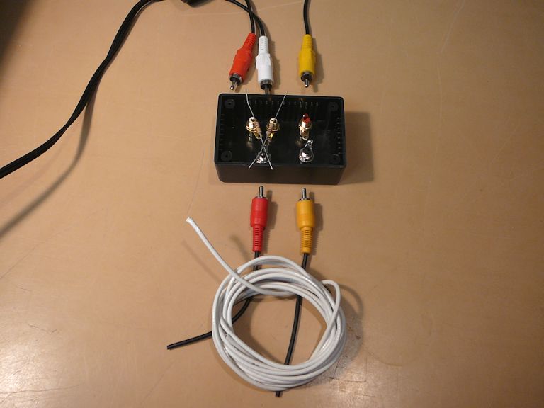
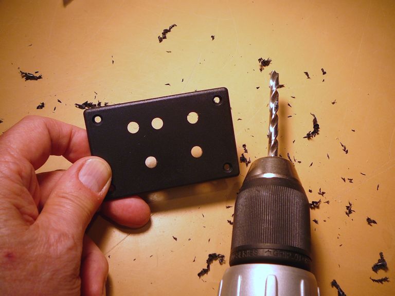
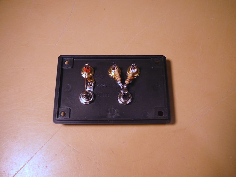
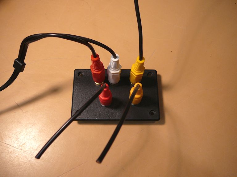
A little junction box will let me plug in the A/V output from a DVD player, etc.,
and send that to the TV's injection points. I'll use two 10K resistors to sum the stereo audio channels into
a single mono channel. Shielded cable will carry the signal to the injection points.


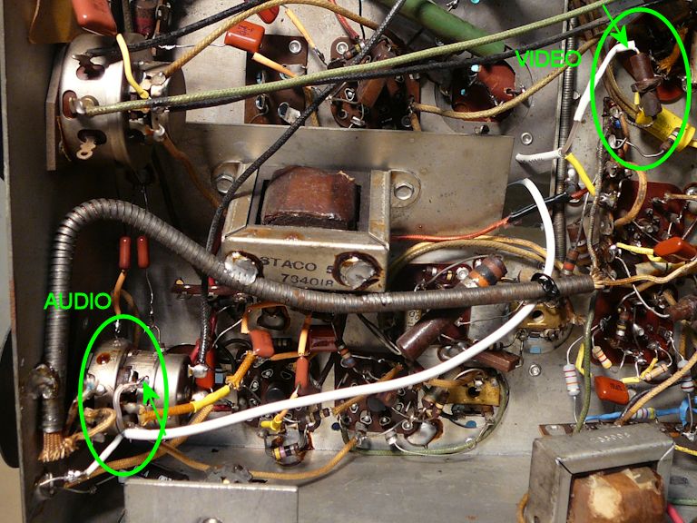
After I wired up the injection signal cables, they were routed through the top (tube) side of the chassis and
soldered in place. The audio cable connects to the Volume control and the video cable
to the peaking coil leading to the video output tube:

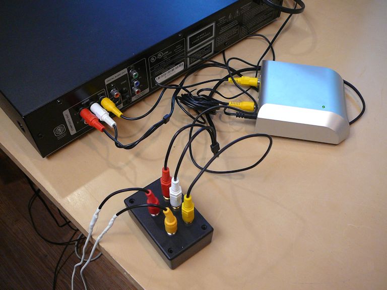
Here's the first trial of the injection setup, sending A/V output from a DVD player
to the TV. (The small silver box is a video stabilizer, needed to eliminate jitter from
playing a copy-protected commercial DVD on this vintage TV.)


The results of direct injection are gratifying—crystal clear audio and a sharper picture!
I would call this installation semi-permanent. To restore normal operation, you only need
to unsolder these two cables and resolder the original connections. With a little more work,
as described in my A/V adapter article, you can make the adapter switchable,
letting you flip between normal operation and direct A/V input at will.
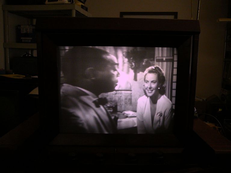
Viewing a Projection TV
I reinstalled the main chassis and made a few last tweaks to the screen geometry. Here is the
Emerson 609 in action:
You can watch this set in a daylit room, but, as with most 1940s TVs, the picture
looks best when you dim the lights. The previous photo was made by putting
the camera on a tripod and taking two photos: one with the room lights up and the other
with lights down. I pasted the screen from the lights-down version into the
lights-up version, to better show how the TV looks in person.
This animated .GIF flips between the two source photos:
Your viewing angle matters, too. The picture looks best when you sit
directly in front, and it fades if you move far to the side (or up or down).
In part, this is a consequence of enlarging a tiny image and projecting it onto a
big screen. The size of the image on the 3NP4 picture tube face is
only 1.4 by 1.86 inches, and that image is enlarged about 8.5 times to make a final image
of 12 by 16 inches.
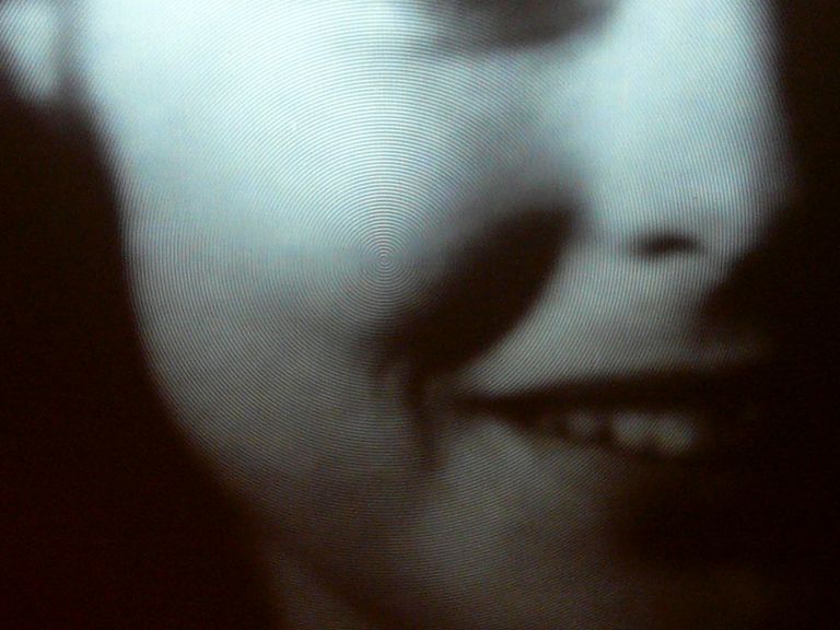
I was still curious about the pattern of tiny concentric grooves on the front surface of
the big display screen:
The grooves are imperceptible at a normal viewing distance, but you can
see them if you put your face next to the screen. Here, I heightened the contrast to exaggerate the circular pattern:

Is the pattern intended to act as a Fresnel lens, intensifying the
image? Does it break up the natural pattern of horizontal scan lines, making
the image a bit smoother and more movie-like? Does it improve the quality of
the image seen from an angle, rather than head-on?
When I raised this question in the Antique Radios TV forum,
forum member Mark Nelson explained:
Those concentric patterns in the screen's front surface are indeed a Fresnel lens. Its
purpose is not to magnify the image but to gather and aim the CRT's light forward, like
the lens in a lighthouse (the purpose for which M. Fresnel invented it). The random-ish
scratches on the other side of the screen are a simple way of making that surface
translucent, and perhaps slightly defocussing the scanning lines.

These were techniques still being used when I worked at Magnavox (actually, North
American Philips) in the early '80s, designing circuits for projection TVs. A lot of
computer time (all done remotely with an acoustic modem connection to a Teletype console
adjacent to my lab) was spent by the optical folks who tailored the shape of the
lenticules in the lenticular screen so that the widest possible viewing angle could be
achieved without brightness fall-off or color shift. I was glad to be working on
electronics -- the optics looked pretty daunting. And your restoration has only
renewed my opinion!
If you view the 609's screen from various angles (up and down, as well as left or right), you'll
see the best contrast and brightness within roughly 45 degrees of a head-on view.
At more extreme angles, the picture is still coherent, but with reduced brightness
and contrast, appearing in shades of gray rather than vivid blacks and whites.
Final Thoughts
Here is the Emerson 609 after I gave the cabinet a light touch-up:
The final detail will be to fabricate a new wooden back cover. Some projection TVs enclose
the entire image path in a black fabric hood, but the Emerson relies on a solid back to
exclude stray light from the picture-making chamber.
This has been an absorbing restoration, but after puttering with this set for more than
a year, I'm ready to move on. And, while it was fun to restore a projection TV, I'm not
sure that I'll ever tackle another one!
|