DuMont Model RA-102 Clifton Television (1947)


DuMont's model RA-102, housed in the Clifton cabinet, is a highly coveted early television
and I consider this one a highlight of my collection.
This early DuMont "televisor" was introduced in 1947, during the infancy of American TV production.
Its look recalls pre-war British televisions such as
Cossor,
HMV,
and Marconi,
but its electronics are emphatically post-war, with a twelve-inch picture tube, FM/AM radio reception,
and several modern all-glass miniature tubes.
DuMont products were well designed and aimed at a luxury market. The RA-102 sold for about $800 at
a time when a new American auto might cost $1500.
Here are two 1947 newspaper ads for the DuMont Clifton, courtesy of the Duke University ad
archive.
The first, from the New York World Telegram, has a sporting theme and urges you to "Get More Out of Life with Television." A small inset diagram credits Herbert Rosengren with designing the Clifton cabinet.
The second ad, from the New York Times, declares that "They're off!" and "You're There!"
with DuMont television, viewing sports from "the best seat in your house."
The second ad lists a price of $795 for the Clifton, available at Liberty Music Shops in three New York locations.
Music stores may seem odd venues for TV sales nowadays, but in 1947—the nascence of commercial television
history—nobody knew exactly where TV marketing was headed, and a store that already sold expensive
entertainment goods like pianos was a sensible place to start.
Description
Once you lay eyes on a Clifton, you won't mistake it for any other TV.
It has a stout cabinet, two large dials below the screen, and six knobs in a
cluster between the dials. These photos show my set
before and after electronic restoration (the cabinet is yet to be refinished):
Here is a feature summary from the DuMont manual:
The Model RA-102 receiver is a complete home entertainment unit featuring television, FM and AM
reception. The set is housed in either the Clifton style cabinet, employing a 12-inch
diameter cathode-ray tube (12JP4), or the Club style cabinet, employing a 15-inch diameter
cathode-ray tube (15AP4). Other than the difference in the size of the cathode ray tube
the circuits are identical. The receiver incorporates 34 vacuum tubes mounted on two chassis,
the main and the power supply chassis. Many features are included in the model. Such circuits
as flywheel sync and the Inputuner are indicative of advanced design. Continuous wide
range tuning (44-216 mc) is used for both television and FM, while a separate AM channel
is used for AM.
The RA-102 chassis was used in two TVs with different picture tubes:
the 12-inch Clifton console and the 15-inch Club. The
Club, as the name implies,
was designed for use in a tavern or similar venue, where it could sit on a shelf or hang
from the ceiling.
The RA-102 service manual is available from the Early Television Foundation schematic
archive.
Click on the icon below to view the 6-megabyte PDF file; to download it to your computer,
right-click the icon and choose Save Target As.
The Clifton was produced in early and later versions, both of which are shown
on the front page of the manual.
The early (RA-102B1) version has five knobs between the big tuning dials.
Mine is the later (RA-102B2) version with six knobs; the extra knob is for the focus control.
The RA-102's needle tuning meter is unusual. It's mounted behind the big left dial and it
operates in TV mode and FM radio mode. DuMont included tuning indicators in other early TVs, including
my DuMont RA-103 and
RA-113, but those sets used a 6AL7 "magic eye" tube
whereas the RA-102 had a mechanical meter with a needle.
Some people call Allen DuMont the father of the magic eye tube, considering his 1932 patent
(US2098231)
for using a cathode-ray tube as a tuning indicator. (RCA paid DuMont for rights to this patent
a couple of years later and went on to develop the eye tubes widely used in the 1930s and 1940s.)
It's not surprising that he would use magic eyes in his televisions fifteen-odd years later,
but I wonder why he used a needle meter in the RA-102, since
magic eyes, and practical circuits for using them, were very well known by 1947.
This television/radio uses 34 tubes in two chassis. The main chassis has 27 tubes:
| Tube |
Type |
Function |
| V1 |
6AU6 |
Video IF Amplifier |
| V2 |
6AU6 |
Video IF Amplifier |
| V3 |
6AU6 |
Video IF Amplifier |
| V4 |
6AC7 |
Video Amplifier |
| V5 |
6AL5 |
DC restorer/delay relay |
| V6 |
12JP4 |
Picture tube |
| V7 |
6BA6 |
FM audio IF amplifier |
| V8 |
6BA6 |
FM audio IF amplifier |
| V9 |
6AU6 |
Audio limiter |
| V10 |
6H6 |
Audio discriminator |
| V11 |
6BE6 |
AM converter |
| V12 |
6BA6 |
AM audio IF amplifier |
| V13 |
6AT6 |
AM detector/Amplifier |
| V14 |
6V6 |
Audio amplifier |
| V15 |
6SN7 |
Sync Amp/Separator |
| V16 |
6SN7 |
Sync clipper/Vert saw gen |
| V17 |
6SN7 |
Vertical deflection amp |
| V18 |
6SN7 |
Sync clipper/Horiz saw gen |
| V19 |
807 |
Horizontal deflection amp |
| V20 |
807 |
Horizontal deflection amp |
| V21 |
6AS7 |
Horizontal damper |
| V22 |
6H6 |
Phase discriminator |
| V23 |
6K6 |
Oscillator |
| V24 |
6AC7 |
Reactance tube |
| V101 |
6J6 |
RF amplifier |
| V102 |
6AK5 |
Converter |
| V103 |
6J6 |
Oscillator |
The power chassis is mounted in the base of the cabinet and it uses seven tubes:
| Tube |
Type |
Function |
| V1 |
6SN7 |
Oscillator/HV regulator |
| V2 |
VR105 |
Regulator |
| V3 |
807 |
Amplifier |
| V4 |
8016 |
High Voltage Rectifier |
| V5 |
5U4G |
Rectifier |
| V6 |
5U4G |
Rectifier |
| V7 |
5U4G |
Rectifier |
The low-voltage power supply is robust, employing a mammoth transformer and three 5U4G rectifier tubes.
The high-voltage supply uses fives tubes, including a VR105 voltage regulator.
The B+ supply incorporates a delay like the one in my DuMont
RA-103 TV. The delay serves the following
purposes, to quote the service manual:
- Automatic cathode-ray tube cut-off when television is not used.
- Cathode-ray tube screen protection.
- Prevents excessive voltage being applied to capacitors before set warms up.
As in the RA-103, the delay promotes longevity and reliability, important factors for
TVs that cost as much as cars. This feature was not widely adopted by
other manufacturers, no doubt to save money. The only non-DuMont set in my collection with
a similar delay is my CTC-7 color set, which uses a cheaper
electromechanical switch.
Finding the RA-102 Clifton
My Clifton came from the estate of Elli Buk, whose vast collection of scientific and technological
items was auctioned in New York in April, 2013. There were three Cliftons in that collection;
my set was the ugly duckling of the trio, but at least it was complete, excepting the back cover.
I hired Craters & Freighters
to build a crate for the TV and ship it from New York to Washington state, where I live.
The seller was familiar with shipping TVs and he did a good job of securing everything inside the cabinet.
He also provided a plywood back cover in place of the original, and filled the interior with bubble wrap. The TV's
wooden knobs were mailed separately.
The next photos show the process of uncrating after the DuMont arrived.


This TV is very heavy. To spare my back, I
slid the set directly from its crate onto a stout dolly.
First Look
After putting on the knobs, I wheeled my new Clifton outdoors for inspection.
The cabinet shows wear but it has not been abused;
the top looks like someone began to strip the finish.
All eight wooden knobs are original. The knob legends (Brightness, etc.) appear on the knobs
themselves, not on cabinet decals as in my later DuMont sets.

The power supply chassis sits below the main chassis and connects with a thick 10-wire cable.
Indoors, I got a closer look at the machinery. The main chassis doesn't look bad from the front, but a rear view shows
considerable rust and a thick layer of grime.
There's no need to guess about the year of manufacture. Peering in at the rear of one dial, you can see a worker's initials
and the date March 14, 1947:
The seller had warned me that the picture tube was a dud, and my CRT tester confirmed that fact.
Removing the CRT exposes the sweep circuitry in the tower above the main chassis. This
semi-enclosed area has lots of rust!
The second photo shows more things that were obscured before, such as the audio IF transformers
and three electrolytic capacitor cans. The large rectangular piece at bottom is the tuner cover.
That rust looks daunting, but I have dealt with rust before.
Underneath, the chassis and components look reasonably clean:

The power supply chassis looked similar, with a rusty top and clean underside:


This TV's overall condition isn't great — it's not a creampuff! — but
none of that came as a surprise. The seller provided many photos in advance and I knew what
I was buying. Dealing with surface rust and cabinet boo-boos can be tedious, but it's not
tricky. The key electronic components are all present; if they are in usable
shape, there shouldn't be any roadblocks to restoration.
First Steps
I begin all my projects the same way, by testing the tubes, cleaning controls, and doing some other basics
outlined in First Steps in Restoration.
I knew beforehand that the CRT was bad, so I obtained a correct replacement 12JP4 jug soon after buying the TV.
I checked most of the small tubes on my Sencore "Mighty Mite" tester. All but a couple of them looked good.
The TV's three 807 tubes are an early five-pin type that my Sencore can't handle, however:

To check the 807 tubes, I hauled out my Precision 10-12 tester:


That tester was built in 1947, the same year as my DuMont TV. Even then, the five-pin 807 was
somewhat obsolete. It's not listed in the tester's roll chart of settings for common types,
but it appears in the Precision chart of obsolete and
oddball tubes.
After assembling a complete set of good tubes, I cleaned all their pins as well as their sockets on the
chassis. I also gave the potentiometers a preliminary cleaning, spritzing a little DeOxit inside their
cases and turning them all the way back and forth several times. A few of them were hard to
move, even after lubricating their shafts; I made a note to check them more closely later.
Preliminary Cleaning
At this stage of a project, I typically give the chassis a thorough cleaning. If you do it section by section, while you
remove and reinstall each tube for testing, before long you will have a nice, clean chassis.
The dark, dirty layer on this chassis is not ordinary grime; I wonder if the TV was stored in a damp salt air environment?
This tough layer was immune to wiping off with paper towels and cleanser, but Naval Jelly worked better:


In contrast to the steel (or plated steel) chassis, the aluminum cover of the tuner case
cleaned up easily:


Rust removal will take hours and it's boring, so I attacked the job bit by bit, between
more interesting tasks. The next photo shows progress, but there's more work to do:
Replacing Electrolytic Capacitors
The DuMont RA-102 has two dozen electrolytic capacitors. I won't show how I replaced all
of them, but here are some highlights, showing how I used different methods in different situations.
(You can read more about capacitor replacement in my recapping article.)
The Uncrimp Method
Every circuit in the TV depends on the power supply, so I began with the three
electrolytic cans on the power supply chassis. The row of three cans is an important visual feature
on this chassis, so I used what you might call the "uncrimp" method to preserve their
original appearance.
I removed the old can completely, uncrimped its containing rim, replaced the innards with new caps (or cap),
and then recrimped the rim. When you're done, the can looks original and
you can reinstall it just like a new one.


An advantage of the uncrimp method is that you don't cut the old can,
so it looks fully intact from above. The downside is that
uncrimping and recrimping is a finicky task.
The Cut-and-Drill Method
The power supply chassis has three electrolytic cans and the main chassis has five more.
One of those cans, capacitor C24, sits in a rear corner of the main chassis. This location
allows me to use a different method, which you might call cut-and-drill.

I'll saw off the old can, remove
its innards, and install four new caps connected to the original terminals through
tiny holes drilled in the capacitor base. This method preserves the original appearance
(after you glue the empty can back on) and it has the advantage that you don't disturb
the old connections under the chassis.
The four electrolytic caps will be installed in the emptied C24 can and connected to the original terminals
(circled) under the chassis:


After removing and emptying the C24 can, I drilled holes in the can's base for the new
capacitors' leads. Then I soldered the leads to the original terminals and epoxied the
can back into place. From above and below, the repair is almost undetectable.
The Cut-and-Glue Method
That one was easy, but the four cans remaining on the main chassis are nestled in tight spots
where my saw can't reach:

For these, I'll unwire the capacitor leads underneath and untwist the metal tabs
to remove the whole can from above. Then I'll cut the can, remove its innards,
drill holes in the base, install the new caps on the base, and glue the empty can to the
base.


Now I have an original can with new caps inside. I can install it just like a new can.
The only sign of repair is a thin line of epoxy at the base.

The next photos give an under-chassis view of installing a restuffed can. In the first pic, I have reinserted the
can's tabs through slots in the chassis and twisted them to secure the can. In the second
shot, everything is reconnected and that can is ready to go.


Whew! I have restuffed seven electrolytic cans. After I deal with one more,
I can do the first power trial.
Incidentally, when working under the main chassis, you can improve access by temporarily removing
these rods, which extend potentiometer shafts to the front panel:

Replacing a 600V Box Capacitor
This TV has an unusual electrolytic capacitor, housed in a big box-shaped metal can.
It is labeled C11 in the power supply schematic, rated for 10 mfd and 600 volts:

Why so big? Perhaps the higher voltage rating (600V) required a different
construction than conventional electrolytics of the day. The can is soldered shut,
suggesting it might even be filled with oil rather than paste
electrolyte like everyday caps.
I can't restuff this can because a modern 600V electrolytic of
the right value is too wide to fit inside. Instead, I disconnected the old
cap and wired a new one under the chassis, where it fits with room to spare.
The old can is left atop the chassis for appearance.
Coincidentally, I found another giant box cap like this in my DuMont
RA-103, where some tinkerer had miswired it
in place of two other electrolytics:

First Power-up
It's always interesting when you apply power to a partly-restored vintage TV for the first time.
With newer sets, the TV may work after a fashion, at least producing noise from the speaker,
if not a picture, but I don't expect any miracles at this stage.
My RA-102 is still loaded with dozens of bad paper capacitors; I haven't checked any
resistors for correct values; and there are other parts like the video
detector whose condition is unknown.
Instead of looking for a picture, I want to learn whether the power supply is basically operational.
Is filament voltage reaching all the tubes? Is B+ power supplied in (approximately) correct
voltages in all the right places?
Here are the two RA-102 chassis hooked up and ready for voltage testing:

For this trial, I temporarily installed my 5AXP4 test CRT in place of
the stock picture tube. Since I don't expect the TV to work fully, I didn't connect an antenna or other signal source.
Plugged into my 7.5-amp variac is a Kill-a-Watt meter to watch
the TV's current draw. Nearby is the voltage chart from the Riders manual.
My Fluke multimeter will be used to measure voltages, and I'll use
tube extenders to access tube pins as needed above the chassis.
The RA-102 passed this initial test. I found filament and B+ voltages where expected, and the
TV didn't draw excessive current. Wahoo!
High voltage is absent, but that's no surprise. Apart from testing tubes and replacing electrolytics,
I haven't done any work on the power supply chassis or the horizontal sweep section on which
the high voltage supply depends.
Painting the Power Supply Chassis
In the previous photo, you might have noticed that my power supply chassis magically
gained a like-new appearance, contrasting with the still-rusty main chassis.
After I replaced the electrolytic cans on that chassis, I spent a long time on rust removal,
but it still looked sad, so I threw in the towel and repainted it.
This was a two-step process. First, I masked off everything except the black parts (transformers
and high-voltage cage) and repainted them black. Next, I masked off everything except the chassis
itself, and painted that a metallic color.


Here's the repainted chassis, next to the as-found photo for comparison.
Painting is a last resort, in my book. Most of the time, simple cleaning and polishing
will make a chassis presentable.
Replacing Free-Range Electrolytics
At this stage, the TV still held several more "free-range" electrolytic
capacitors—that is, caps located at various spots under the chassis rather
than penned up in cans.
Here's a typical one: C65, a 25-mfd/50-volt electrolytic connected to V16, a 6SN7
tube that performs double duty as the sync clipper and as the vertical sawtooth generator:

In that photo, I'm holding the old cap next to the new one, which is already installed.
The new part is tiny compared to the original—a factor that frees up
space in this cramped area under a tube socket.
Replacing Paper Capacitors
After finishing the last electrolytic, I turned my attention to the RA-102's many
paper capacitors. Here is C68, a .01-mfd cap located near the same tube (V16):


As the hours pass, the pile of discards grows:

The pile also includes many resistors.
When I replace a capacitor, I usually test any resistors connected to the same terminals.
Then I can replace the bad parts in that area all at once, without disturbing the connections a second time.
This television had some minor repairs during its original service lifetime. Amid the
collection of pale blue Solar brand paper capacitors, you'll see three newer replacements: two thick black
"bumblebee" plastic-coated caps, and a pink Big Chief brand plastic cap. Later in
this article, we'll see some ugly attempted repairs in the high voltage section.
Replacing Resistors
My next step was to check resistors more systematically, looking at all of them, not only those that share
a capacitor connection. Carbon composition resistors often drift upward in value with age, and in most TVs,
you'll find a few bad apples. That was true of this RA-102, and I also found
that virtually every 470K resistor was far out of tolerance. Here's an example, resistor R47:


In a restoration of this scale, it's prudent to record your progress. Digital photos are virtually
free, so I often photograph each component as I replace it, and
check off that part on the TV's schematic and parts list. This helps to prevent head scratching
later, when you wonder whether you replaced Part X with one of the right value and with the proper connections.
Second Power Trial
After replacing a bunch of resistors, I hooked up the TV for another trial under
power. As before, the basic operating voltages were present, but there was no high
voltage output.
Without HV, there is no picture, but I can use an oscilloscope to check some
circuits, comparing their waveforms to the model waveforms shown in the Riders manual.
Here are a couple of photos taken during this phase.


For this trial, I used my Philips PM5518 TV pattern generator and my trusty old
BK Precision 1474 oscilloscope.
The waveforms looked good in the sync and sweep sections, but not in the
video section—specifically, on the output side of the video detector diode.
This diagram marks the spot where I connected the scope:

The 1N34 video detector diode feeds its signal to V4, the video amplifier, which sends video
to the picture tube. By scoping this test point, I can tell whether the detector diode is
passing a coherent signal. When I tried that, the waveform at the test point didn't
resemble the input signal at all:

For this trial I used a color bar pattern, which makes a distinctive stairstep
trace on the scope when all is well.
The prime suspect is the video detector, a type 1N34 diode that is known to
fail. Here, I'm holding the old diode next to the new one that I
installed in its place:

With a new diode, the waveform is a stairstep as we'd expect from this test pattern:
We're making progress. The TV is producing approximately the right waveforms in the vertical and horizontal
sections. Coherent video output at the detector means that the preceding RF and IF stages are passing a
reasonably good signal. If I can get the high-voltage circuits working, there's a chance of
seeing a picture!
Repairing the Inter-Chassis Cable Connector
This TV's two chassis are connected by a thick multi-wire cable, and when I unplugged it
after this power trial, I saw that the cable's big connector was getting loose. Here are the plug and
socket viewed from above the main chassis:

The connector resembles an eight-pin tube socket, but it's not identical.
It has ten stout pins—nine around the perimeter and a tenth nearer the
center. When I posted a query
in the Antique Radios forum, nobody could suggest a replacement for this oddball.
I'll need to unplug and plug this cable many times before the restoration is complete. Since
new connectors aren't available, I'd like to fix this one somehow. Of course, I could replace
both the plug and socket with something like the 12-pin Cinch Jones connector used in my
Scott 800B radio/TV/phono, but that would mean reshaping the circular
socket hole into a rectangle and losing some originality.
The broken part is located under the chassis. A black plastic retaining collar has snapped loose and
a few bits have disappeared. If I don't re-secure the supporting collar, the stress of repeated use
will break these wires.


JB Weld to the rescue! With toothpicks and a fine dental tool, I molded
epoxy under the collar and around it, securing and reinforcing the connector.


Now I can work without fretting over broken wires.
Repairing a Loose Tube Grid Cap
Speaking of breaks, when I removed the grid connector from one of the 807 tubes, the tube's metal cap pulled off. Oops!

Fortunately, the grid wire at the top of the glass envelope is intact.
I can salvage the tube by regluing the cap and resoldering the wire to it.

I scraped the old glue out of the cap and removed the old solder, making certain to clear out the cap's tiny hole.
I gently scraped the wire bright, to ensure a good joint. In cases where the wire has broken and won't reach
the cap's hole, you can lengthen it by carefully soldering on a wee extension.


I glued on the cap and let the epoxy cure overnight before resoldering the cap. Notice that the
top of the cap has a shallow moat around the wire's hole. When you solder it, fill the
entire moat with melted solder. Don't hold your soldering iron on the cap longer than necessary,
however; excessive heat might crack the glass.


After this simple repair, the cap is back on and the tube tests like new!

There's no excuse for discarding a tube with a loose grid cap, until you have at least tried this
easy repair. Even if the grid wire has broken off nearly flush
with the glass, there may be hope. In my Farnsworth 661-P
article, you can read how I used silver-filled epoxy to repair a picture tube with a teeny broken wire stub.
Restoring the AM Radio
The RA-102 includes an AM radio on the main chassis. This is in addition to the FM radio,
which is implemented through the TV's continuous tuner, as we'll read later.
The AM radio portion of this set is rudimentary. It uses three tubes: a 6BE6 for the converter
stage, a 6BA6 for the IF amplifier, and a 6AT6 as the detector/amplifier. Final amplification of
the audio is handled by a 6V6 tube and that output stage is shared by the FM radio and TV.
Since I had previously replaced the paper capacitors in the AM radio sections, along with a couple
of 470K resistors (those were everywhere!), it wasn't surprising to hear the radio work during the
latest power trial. The tuner was scratchy sounding and stiff, however, so I loosened the
tuner mechanism and tilted it out for cleaning and lubrication. I also used this opportunity
to remove rust from the area.
The AM dial is located on the left side of the chassis. I could see at a glance that the
brown background paint was flaking off behind the dial. Near the top of the dial is the set's
signal meter, which is viewed through a cutout in the dial housing.

The Lucite dial scale is attached to the tuner shaft with two Allen setscrews. Later
in this project, I'll repaint the dial backing brown. On the rear of the dial housing
are the initials and date (DD 3/14/47) that we noticed earlier. I wonder if D.D. was an inspector on the
assembly line?


With the dial out of the way, I can remove the dual pilot lamp assembly from
the top of the tuner frame. I'll also clean the signal meter.

After loosening the mounting screws, I can tilt the tuner forward to clean and lubricate the mechanism, which
was the main reason to dig this deep. The chassis near the tuner base
has serious rust, which I'll remove with Naval Jelly now that I can reach this cramped area.


While I'm in the neighborhood, I may as well unbolt the center front panel, loosen the controls,
and clean the potentiometers and mode switch.


The mode selector switch is critical because it's used to flip the set between
television, FM radio, and AM radio modes. A dirty contact here could kill an entire section.
Liquid DeOxit is a good cleaner for this job.
Now the AM radio assembly is back in place:

Notice the arrangement of the pilot lamps, which light at different times when you switch modes.
The topmost one lights the AM dial from above the little brass shade, while the other one illuminates the signal meter
from under the shade.
After this refresher, the AM radio sounded good. In case you're wondering, this
radio uses a loop antenna stapled inside the cabinet:


Despite its scraggly appearance, the antenna works fine when plugged into the chassis. I'll
check the AM radio's alignment in the final-tweaks phase of this project.
Servicing the Continuous TV/FM Tuner
As noted earlier, the RA-102 uses a continuous tuner for both television and FM radio reception.
(You can read more about continuous tuning in my DuMont RA-103 article.)
These tuners are accurate and reliable, but many of them suffer when their
lubricant dries and hardens during decades of disuse.
Caution: if your DuMont tuner turns stiffly or it's completely frozen, do not force it. You might break
a gear, as happened with my
DuMont RA-113, or cause other damage.
When I purchased my RA-102, the tuner was immovable, so I left it alone until I could
disassemble it for cleaning and lubrication.
The tuner is mounted on the chassis front corner:

It's possible to service the tuner without unsoldering its leads and removing
it completely from the chassis. First, I removed the tuning knob, which is held on its
shaft with a setscrew. An angled screwdriver is handy for removing the cover screws:


Now we can see the tuner spirals, which are described in my other DuMont articles.

I'll clean these parts eventually, but first I need to remove the dial assembly
to access the gears and free the immobilized tuner.
The dial frame is held by two screws under the chassis and three on the side.
The under-chassis screws are blocked by two potentiometers (Horizontal Position
and Vertical Position), which you must loosen and nudge aside for access:


Take care not to tear anything loose or create short circuits when you maneuver
those pots out of the way. After removing the bottom screws, remove the side screws
and pull the dial and its frame off from the front:

We have exposed the Achilles heel of the continuous tuner: a gear assembly
caked with petrified grease:

The old lubricant dried into stiff gunk and froze the
mechanism. Notice the heavy scoring of the shaft, caused by a
frustrated user who tried to force the tuner. The extra torque
made the knob slip on its shaft, while the tuner stayed immobile.
I removed the gunk with lacquer thinner, a brass brush, and a toothpick.


Moving inside the tuner compartment, I used a soft brush and more lacquer thinner to
rinse old lubricant from the ingenious end-stop mechanism (which is
described further
in my RA-103 article).

I applied light oil to the end-stop mechanism and rear bearing, and
lubricated the front gear assembly with light grease:

Now the tuner moves freely and I can clean its inner contacts with DeOxit:


It's prudent to clean the tuner contacts, even if your tuner isn't physically stuck.
Notice that I didn't pull the tuner completely apart to check its other internal
components (largely resistors and caps). Tuner internals are extremely reliable
and messing with them for no reason may do more harm than good.
Whew! It's nearly time to put this gizmo back together.
This dial scale has some cloudiness on its inner surface, so I'll remove it
from its frame for cleaning:


Strangely, although the brown background paint on the AM dial backing fell off in big chunks,
the paint on this back is intact.
The dial scales are quite dirty. The light film is probably ordinary
household grime, but don't ask me how this stuff (flyspecks?)
got onto the back side:

This scale looks perfect after a gentle application of lens cleaner:

Painted markings can be delicate, so if you need to clean the painted side of a scale, always begin with
very gentle methods and avoid scrubbing.
When you reinstall the dial frame on the main chassis, you'll want to position the dial scale at
the right spot before meshing its driving gear with the main gear assembly.
I turned the tuner shaft fully counterclockwise (i.e., down to TV Channel 1) and then positioned
the scale as shown:

Now I can secure the dial frame and replace the tuner cover.
After reassembling the tuner, I removed more rust from this area with Naval Jelly. Bit by bit,
the chassis is looking more civilized.

A Survey of the High Voltage Section
After all this work, I still had no high voltage, hence no picture. At this stage I
had replaced paper and electrolytic caps on the power supply chassis, but ignored the
high voltage section, which is circled in the following photo. The HV components
are exposed after you remove the black metal cover:

The RA-102's high voltage supply consists of an oscillator tube, amplifier tube,
transformer, rectifier tube, and capacitor to filter the HV output.
This schematic shows the complete
power supply chassis, including the HV components (near the top):

Here is the service manual's description of the high voltage supply:
A pulse type power supply is utilized to obtain intensifier voltages.
One-half of V1 (6SN7) is used as a blocking oscillator. This stage is
triggered by the "BTO sync" signal that is obtained from the
horizontal sweep. Failure of the horizontal sweep, therefore, causes
failure of the high voltage power supply. The pulses obtained from
the blocking oscillator are amplified by V3 (807) and then fed to an
auto transformer. Amplification is again accomplished by transformer
action (T2). Rectification is afforded by V4 (1B3GT), a diode. Filter
action is accomplished by an RC filter (R12, C8, R12) and the capacity
of the high tension lead.
A part of the output is obtained by voltage divider action for use in
the regulator circuit. Changes in magnitude of the high voltage cause
voltage changes across the regulator tube. This in turn affects the
pulse amplifier, thus controlling the size of the pulses. All changes
are in a direction so as to correct the original deficiency.
Here is the HV supply after I did some work on this chassis:

In that photo, from left to right, you can see the 6SN7 oscillator, 1B3GT rectifier, and 807 amplifier. Behind
the tubes is T2, a tall air-core transformer with seven pie-shaped windings stacked vertically.
Although the HV section contains few components, it consumed a lot
of time in this project.
Refurbishing the Voltage Divider Board
Let's begin with a simple component. The voltage divider is a
phenolic board holding a chain of twelve 15-megohm resistors (both sides of the board contain resistors).

These resistors form a single 180-megohm resistor (R10) that acts as a voltage divider
for the power supply's HV regulator control (R9).
Testing showed that several resistors were out of tolerance, so I replaced all twelve.
This made it easier to clean the board, which was caked with tough grime
despite being protected inside the high voltage cover.
Eventually, the crud was gone and new resistors were in place.


Whither the Doorknob?
That concluded the good news for this section. I had earlier noticed that the grid cap connectors
from transformer T2 to the 1B3GT and 807 tubes had been crudely replaced.
Not only that, but someone had modified the circuit to remove the 500-pf HV filter capacitor (C8).
After removing a wad of crusty old electrical tape, I could see two unattached brass connectors
for C8, a large "doorknob" style ceramic cap:

What's going on? I'm guessing that the previous owner substituted
a picture tube that used an aquadag coating as the HV filter, rather than an external doorknob cap.
For instance, a type 12LP4
CRT is electrically compatible with the original 12JP4
and it also has an aquadag coating. If you installed a 12LP4, you could eliminate the redundant doorknob.
I'm using an "original recipe" 12JP4 picture tube that needs an external filter,
so I'll put a new doorknob cap where it belongs and restore the HV wiring as given in the schematic:


Resistor R13 forms part of the HV filter and it is badly out of tolerance. To replace it,
I'll need to remove the 1B3GT rectifier socket, which is necessary anyway, to replace the crumbling
insulation on the two slender wires that connect the transformer to the rectifier's filament pins.


As with the divider board, installing a new doorknob was simple, once I noticed
that it was missing.
Interlock Switch
Another missing component on the power chassis was S3, the back-cover interlock switch.
This is a momentary-contact pushbutton that mounts on the rear of the power chassis.
When the back cover is screwed into place, the button is pushed in and the TV can be powered up.
When the cover is off, the interlock switch opens and all power is disabled.
That's a nice safety feature for consumers, but annoying to the repairman
who needs to remove the chassis and power it up on the workbench. A past repairman
removed the switch from my RA-102 and wired around it, and I decided to leave that
alone for now. I don't have a back cover and there's no reason to install a switch
that I'll need to tape down permanently.
A Damaged High Voltage Transformer
Now, we get to the ugly stuff. When I removed more crusty old electrical tape,
I saw that the connection from the transformer to the 807 tube was literally hanging by a thread!

It looks like the original wire was torn loose somehow, and a repairman tried to
resolder a connector to the hank of loose wires hanging off that coil. I doubt the
TV could have worked at all in this condition. Perhaps a repairman tried
to fix this torn connection and the TV was retired when his attempt failed.
This damage looked ominous, but I decided to connect the transformer and see whether it could
make any output at all. I did my best to clean up the mess and solder a secure connection to that
part of the transformer:
Here is the entire high voltage section after I restored the factory wiring above the chassis.
Replacing Ruined Potentiometers
Before trying another power-up, I checked the two potentiometers under the power supply
chassis: R8, the high voltage Regulator control, and R9, the output Voltage control.
These are carbon type potentiometers, which change
resistance as the turning shaft moves a metal wiper around a resistive carbon track.
Tests on these pots indicated failure, and when I opened them for
inspection, the cause was obvious: their carbon tracks had literally fallen to pieces:

No amount of cleaning will revive those relics. Out with the bad, in with the good!

I have rarely seen such dramatic failure in a potentiometer. Perhaps, like the extensive
chassis rust, this resulted from storing the TV in a damp environment. When I return to the main chassis, I'll
take a close look at all its pots.
The HV Transformer Fails
When I powered up the TV, the result was disappointing. The high voltage supply initially generated
only about 1.5 kilovolts—far below the 10KV that's ideal for this picture tube.
Worse, after a minute or so, I heard the faint hiss of high voltage on the loose. Blue-white corona
dots appeared near the repaired spot on the HV transformer, and the HV output soon
disappeared altogether. This snapshot shows one of the corona spots:

I powered down and resoldered the connection that I had made to the transformer's bum
spot, but the results were no better. And there was more bad news. Closer inspection revealed a tiny broken wire stub
projecting from the opposite side of the transformer, on the topmost pancake winding. In this photo, I had
peeled the stub outward to make it more visible:

Clearly, this transformer needs more than a Band-Aid!
I have read about repairing this kind of coil damage, but I'm not adept at
such micro-surgery. The idea is to gently peel off loose wire until you
find a break, then restore the connection. Simple in theory, but tricky in practice, since the
hair-thin wires are hard to manipulate and if you apply too much heat to a
wire, it may simply vaporize.
Wanted: One-of-a-Kind HV Transformer
The best solution would be to find a new transformer.
I contacted likely suppliers (Moyer Electronics
and Play Things of Past), but they had nothing to offer.
With its hollow core and stacked pie windings, this HV transformer resembles the RF-type transformers
widely used in 7-inch TVs like my Admiral 19A12, and I
initially mistook it for that type. However, it is a different sort—what DuMont called a
"pulse transformer"—and much less common.
The RA-102 was the only DuMont model to use this transformer. The earlier RA-101 used a completely different
(and dangerous) "brute force" HV circuit; and the RA-103 and subsequent models used
a flyback-type transformer. The RA-102—possibly the only TV ever to use this component—sold in
small numbers, and consequently the aftermarket transformer manufacturers, such as Merit, Stancor, and Thordarson,
had no incentive to offer a substitute.
My restoration has hit a stone wall. Until I can repair the old transformer or find a
substitute, my RA-102 is nothing but a costly doorstop.
Using a Temporary High Voltage Supply
At this time, I was contacted by a VideoKarma forum member who had a salvaged
HV supply for sale. He took it from a 12-inch Westinghouse TV and it worked after recapping.
I bought the supply to try it out. Although it may not be ideal as a permanent substitute, if I can connect it
and get a raster on the CRT, that will let me continue other work on this project while
seeking the right part.
The seller didn't recall the Westinghouse model number, but I searched old Westinghouse
schematics and found the matching circuit in model H-223. This supply is housed
in a light aluminum cage:

Here's how the H-223 manual describes this HV supply:

The schematic shows that I'll need four connections between the RA-102 chassis and this
outboard HV supply: +255V DC for the 6V6 tube's plate, 6.3V AC for its filament, one for chassis
ground, and the fourth to carry high voltage out to the CRT second anode.
When I hooked up the supply with clip leads, I could get my test
5AXP4 CRT to light up, with a semblance of a picture.
(In the second photo, the chassis is lying on its side, so the image on the test CRT is
sideways.)


The vertical sweep refuses to lock, but after months of work, I can finally see a picture!
When I made better connections for the HV supply and tried it
with the big 12JP4 CRT, the picture looked better:
The vertical stubbornly refused to lock, no matter how I adjusted the vertical hold and
other controls, but in other ways, this picture is watchable. Perhaps my Clifton
will come to life some day!
Later, I put the Westinghouse HV supply back into its cage and made more sensible connections between it and the DuMont's power chassis.
Under load, it produced slightly more than 8 kilovolts, lower than the 10KV specified in the schematic:


That voltage level isn't ideal, and now the TV's HV regulator circuit is disabled,
but at least I can work on other parts of the television.
Replacing Carbon Potentiometers
After finding a 100% failure rate in the power chassis' two potentiometers, I decided to take a
close look at pots in the main chassis. All I had done until now was give
them the usual preliminary cleaning with DeOxit.
This television uses a lot of pots. The front of the chassis shows twelve potentiometers:
nine of the carbon type and three wire-wound:

In the lower row of controls, the leftmost five are carbon pots (Horizontal Size, Vertical
Linearity, Horizontal Linearity, Vertical Size, Vertical Hold). The upper panel has four
carbon pots (Volume, Contrast, Tone, and Brightness). The Focus control in the upper
row is a wire-wound pot, as are the Horizontal Position and Vertical Position pots
at bottom right.
In addition to those twelve, there are three pots accessible from the top
of the chassis (Horizontal Peaking, Horizontal Damping, and CRT Bias).
The five pots in the lower row all have long extenders to connect to the controls
on a rack farther back in the chassis. Testing revealed serious problems, so I replaced
all five. In the next photo, I'm about to replace R93, the Vertical Size control:

Before long, all five pots were replaced:

The extender rods let you operate the controls from the front panel, while keeping the control
leads short to minimize interference between circuits. When you're working under the chassis, sometimes it's
convenient to temporarily remove those extenders, as in the next photo, where I'm about
to replace R107, the Horizontal Peaking pot:

Eventually, I got tired of looking at those dirty, corroded extenders. They spiffed up
readily with Bon Ami cleanser and a little metal polish:


Much earlier in the project, I had loosened the upper front control panel
sufficiently to spritz some cleaner into the carbon pots:
Had I known then how wrecked the carbon pots were in this TV, I would have replaced these
four at that time, or at least checked them more thoroughly. Hindsight is always twenty-twenty!
With a sigh, I loosened the panel all over again and installed new pots:

For R76, the Volume control, the new pot's shaft was too short. I harvested part of the
old shaft for an extension, which I glued on with two-part J-B Weld epoxy, taping the two
shafts together and rolling them on the workbench to make the shaft straight:


On the RA-102, this Volume control does not incorporate the on-off switch, as in most modern TVs (the power switch
is on the Tone control instead). This pot won't be subjected to much torsion, so the epoxy joint should
be strong enough.
The replacement pot for R35, the CRT Bias control, had a too-long shaft. I shortened
it with a hacksaw and used a Dremel tool to cut a screwdriver slot in the shaft.


Removing the old CRT Bias pot was difficult because it's located at the base of the
tower that holds three horizontal sweep tubes. This dank corner had the worst rust on
the entire chassis and the Bias pot was buried in a thick layer of corrosion. The next photo
shows the area after I had tried several applications of rust remover, using a scraper and
even a small chisel to remove rust:

When applying Naval Jelly to heavy rust, a layer of cling wrap will keep the
gel from drying out over long periods. After multiple applications, I could finally loosen the Bias pot's
mounting nut and remove the control from underneath:


Lest you think I was indiscriminately "shotgunning" all these pots,
look at the inside of the Bias control:


As in other cases, the resistive carbon track crumbled and fell apart.
This pot is junk.
Eventually, all thirteen carbon pots were replaced. I'm almost done with this phase!
Replacing a Wire-Wound Potentiometer
The remaining four pots are the wire-wound type, normally very reliable. However, one of them—the Vertical Position control
on the front panel—was defective. This pot has a center tap and one half of its range was basically dead.
Not much can go wrong with a wire-wound pot, other than a broken internal connection or horrid corrosion,
so I thought it was worth trying to revive this one. I opened it up and gave it a thorough cleaning and checkup,
but the defect remained.

Guess what—nobody, but nobody sells a wire-wound pot of this value (10 ohms, 4 watts) with
a center tap. Around this time, I learned that VideoKarma
forum member Bob Galanter could install a center tap on a new pot, if needed.
I bought an untapped 10-ohm/4-watt wire-wound pot and mailed it to Bob, who installed the tap shown below and sent it back.
(While I waited for the new part, I temporarily installed a pair of 5-ohm/5-watt resistors in place of the control, so
I could power up the TV while working on other issues.)

The next photo shows the new tapped Vertical Position control in place:

This pot is mounted in a cramped corner of the chassis (which we saw earlier when removing
the tuner dial frame). To replace it, you must loosen and partly remove the adjacent Horizontal Position control.
The position of this pot unavoidably brings the tapped lead very close to the chassis, so make sure
that the lead and its terminal are well insulated to prevent short circuits.
Using an Alternate High Voltage Transformer
While replacing potentiometers, I used the salvaged Westinghouse HV supply from time to time, to power up the TV
and check my progress. It became clear that this supply wouldn't make a great long-term solution.
I'd need to find some place on the RA-102 chassis to mount this bulky assembly. And although it
generated enough HV to light up the CRT, the output was still about 2KV too low, and this alien source
left the TV's native voltage regulator inactive.
In the course of a discussion
in the Antique Radios forum, it was suggested
that I try a Merit HVO-34 high voltage output transformer.
The Early Television Foundation had a Merit HVO-34 in their stock of parts for sale,
and they kindly emailed me the data sheet with specs and an example circuit:
This transformer is rated for 12KV-14KV, more than enough for my needs, and in the example
circuit it plays much the same role as my original transformer. I sent the ETF a donation
and got the transformer.

The transformer is small enough to fit the available space. Let's try it out!


Connecting the 1B3GT rectifier filament leads is simple if you remove the socket first:

A little wooden standoff will hold the transformer while I make some tests (in this early photo,
the leads to the tube caps were reversed, a goof that I quickly remedied):

An advantage of using the HVO-34 transformer as a direct replacement is that the TV's
voltage regulator circuit should be operational, which was not true using the Westinghouse
HV supply. Initial tests with the HVO-34 in place were encouraging. Here I'm checking
some parameters at the 807 amplifier tube:

In a full test using the big CRT, the results were disappointing. The most that I could
coax from the HVO-34 transformer was about 5 kilovolts. That's half the required
voltage level—enough to light up the screen, but too low to be practical.

When the HV is that low, you have problems with focus and blooming, as well as a dim image.
Subbing the Merit HVO-34 transformer was an interesting experiment, but it's not a
drop-in replacement for the original.
Repairing the Original High Voltage Transformer
Neither of the alternate HV solutions panned out, so I was back to staring at
my damaged original transformer. I had contacted a couple of companies who rewind
transformers, but they weren't willing to attempt the job.
Then I remembered Andy Cuffe, a fellow collector who repaired a yoke for
my Sharp 3LS36 television several years ago. I sent Andy an email, including
photos of the damaged transformer.
Andy agreed to look at the transformer if I shipped it to him. He added that he couldn't make
any guarantees—it would depend on what he found when he started peeling wires
from the damaged spots.
I sent the transformer to Andy and soon received this message:
From: Andy Cuffe
Subject: Re: Arcing HV transformer in DuMont RA-102

Well, I've found all the breaks (no fewer than four), so at least it has
continuity from the top to bottom. It's odd that there were so many breaks
in the coil. I don't think it was corrosion, so it may have received
some rough handling in the past. All of the breaks were in the outer layers
of the top three sections.

I'll see if I can test it with my B&K Television Analyst (which I believe has
a flyback plate drive output). Either way, I've done everything I can with
it. If it still arcs, it will need to be rewound which I can't do. I'm hoping
the arcing was taking place at one of the breaks in the winding.
The next day, I received even more promising news:
From: Andy Cuffe
Subject: Re: Arcing HV transformer in DuMont RA-102

I connected it to my B&K and an external B+ power supply. While not conclusive,
the results were encouraging. I was able to get a healthy arc from the HV
rectifier lead, and I didn't see any arcing or corona on the windings.
When I got the repaired transformer back, I could see the neat repairs
to the top windings:

The greenish areas show where damaged wiring was peeled away, exposing
old varnish. The green disappeared when I applied clear corona dope to those
windings and the newly soldered junctions. I baked the transformer in a low oven to cure the
insulating dope.
Andy sent along the hair-thin wires that he removed from the transformer—more than 100 inches in all.

Removing windings from a coil may affect its efficiency somewhat, but I hope that losing
these comparatively small amounts won't matter if the output is within the adjustment
range of the RA-102's high voltage control.
When I reinstalled the transformer and tried it out, the results were gratifying. It easily
generated 10 kilovolts under load:


After a few minutes, I heard the tell-tale hissing sound of corona in the high
voltage area. Darkening the room allowed me to spot it—a faint blue discharge
around the freshly soldered connections under the 1B3GT HV rectifier tube.
It took a few applications of dope to control the corona. First, I applied thick opaque dope
to the solder connections themselves, letting it cure per the manufacturer's instructions.
When the corona was squelched in those spots, it popped out in other places along the HV line,
wherever there was exposed metal. I covered those spots with the lighter dope, which
licked the problem.

Research shows that my set wasn't alone in suffering corona problems.
This DuMont Service Note mentions corona discharge inside the RA-102 high voltage compartment
and recommends steps (chiefly, insulating with corona dope) to cure it:
At last, my damaged high voltage transformer was fixed. Thanks, Andy!
The HV supply was strong and I got response from the HV Voltage
and Regulator controls, as well as the Brightness, Contrast, and Focus adjusters.
With a better picture to view, now I could see the TV's vertical problem more clearly.
Diagnosing and fixing that involved another transformer.
Replacing a Vertical Transformer
The TV clearly had a vertical sweep problem, with some familiar symptoms and one unfamiliar one.
In the familiar category, it was impossible to lock the picture vertically or to obtain
correct height and vertical linearity. These are garden-variety problems, often cured by
replacing bad tubes, capacitors, or resistors, but at this stage I had already replaced all
the capacitors and resistors in the relevant circuit and swapped in a known-good 6SN7GT tube.
More unusually, as the image slowly hovered, you could see slanting lines similar (but
not identical) to the "retrace" lines that appear when a TV lacks retrace
blanking or its Brightness control is turned up too far. This video clip shows the problem;
note how the slanting lines change direction and speed, along with the rolling of the
screen:
Fortunately, this peculiar effect was easy to diagnose. A voltage check
revealed that pin 2 of V16, the sync clipper/vertical sawtooth generator tube, had zero
volts instead of the 180 volts given in the manual. This schematic shows the circuit:
The plate (pin 2) of V16 receives its voltage through the primary winding of T2,
the vertical blocking oscillator transformer. A resistance check of the
transformer showed the reason for the lack of voltage. My ohmmeter
measured infinite resistance—an open primary winding— between the Red
and Blue leads of T2. With no plate voltage, tube V16 can't work right,
and the Red lead is the critical spot where the sync clipper passes its signal to
the vertical sawtooth generator.
During a VideoKarma discussion of this issue,
Kevin Kuehn noted that the long-unavailable DuMont part can be replaced
by a Stancor A-8124 transformer. I got one from
Moyer Electronics:
I carefully marked the transformer's six connection points under the chassis, and then removed
the old unit:

The color coding of the old wires faded to dirty brown decades ago, so I'm glad that I noted
the connections before removing it.
When the new transformer is mounted above the chassis, four of its leads go into one hole and two go into another:

In this view from underneath, you can see six new leads ready to be connected:

The new transformer made a dramatic improvement:
The vertical stopped rolling, the peculiar
slanting lines disappeared, and I could adjust the vertical height, linearity, and centering.
Replacing a High Voltage Filter Capacitor
With a more stable picture, I could notice subtler issues. Now the whole image seemed to expand and
contract in both dimensions—horizontal and vertical—slightly and rapidly. I could also
see faint "retrace"-like horizontal lines, which were light colored in the upper half of the screen
and dark in the lower half. These video clips give you an idea:

The first video shows the expansion/contraction of the image more clearly, while the second shows the
unwanted lines.
Switching to a test pattern gave me another view. At irregular intervals, some kind of blip suddenly changed
the image width (i.e., the length of a scan line) for a portion of the frame:
A blip like that might originate in the horizontal sweep section, but when I viewed the horizontal
waveforms with an oscilloscope, I didn't see any obvious problems. Other ideas were mentioned
in the VideoKarma discussion, including a note from VK member Penthode that the symptoms might
be due to a bad doorknob filter cap.
While I was making those observations, a faint hissing sound returned in the HV section.
This felt like a step backwards, and I was concerned that my previous attempts to defeat corona were
insufficient, or (shudder!) that my repaired HV transformer was arcing internally.
No corona was visible in a dark room and I couldn't pinpoint the source with a listening tube.
To eliminate corona from the equation, I removed the high voltage transformer and
applied thin corona dope over all its windings. I also recoated the connections to the 1B3GT rectifier tube and
other exposed portions of the HV output line. I cured the dope under heat overnight.
When I reassembled everything and played the TV the next day, the hissing returned. Then, after a few
moments, loud static erupted from the speaker and the screen image dissolved into hash. This
looked like a major breakdown in the HV section; perhaps my repaired transformer flamed out or
the doorknob filter cap failed.
It's easy to plug in a substitute doorknob cap, so I borrowed one from my
National TV-7W set, which uses four of them. The
picture immediately returned to normal and remained stable. Wahoo!
I put the borrowed doorknob back into my National TV-7W and ordered a new one for the DuMont.
My capacitor checkers can't test anything with such a high (10 KV) voltage rating, but I was curious
whether the first doorknob cap was truly bad. I had bought it from a well-known
supplier and these ceramic doorknobs are usually very reliable.
I temporarily clipped the first doorknob in parallel with the newly installed
one, and it immediately emitted a loud hiss. The culprit has been unmasked!

Although the capacitor looks undamaged from the outside, it must have an internal crack or
other defect that makes it leak under high voltage.
Adjusting the High Voltage Regulator
Now, the TV had a nice picture, but it tended to "bloom" (expand and lose focus) when
a program switched from a scene of normal light-dark content to a very bright scene, such as a
white advertisement with small dark text.
Displaying a very bright scene increases the demand on the high voltage power supply, and if
the HV supply can't handle the load, the voltage drops, causing the bloom.
Many old TVs have no HV regulation circuit, so you must live with the phenomenon,
setting contrast and brightness for the best overall picture and tolerating some bloom.
The RA-102 has an adjustable HV regulator, however, as we learned earlier:
Changes in magnitude of the high voltage cause voltage changes across the regulator tube.
This in turn affects the pulse amplifier, thus controlling the size of the pulses.
All changes are in a direction so as to correct the original deficiency.
In short, if the HV output sags under a heavy load, the voltage regulator gooses it back up
to the right level.
To adjust the voltage regulator, I used two patterns from my Phillips TV pattern generator.
The first, a crosshatch, is mostly black with thin white lines. The second pattern is
the same thing inverted: mostly white with thin black lines.


Switching from the mostly-black image to the mostly-white one will replicate the appearance
of a very bright scene in normal program content, and I'll be able to measure the
resulting HV levels in a controlled setting.
With my HV meter connected at the source, I confirmed that the mostly-white screen
pulled the HV voltage down, anywhere from 1KV to 2KV, depending on
how I set the Brightness and Contrast controls up front.

The Regulator and Voltage controls are screwdriver adjusters on the side of the power chassis;
the Regulator is next to the fuse holder. Earlier in this article, we saw that I replaced
both controls (R8 and R9 in the power supply schematic):

By watching the screen as well as the HV meter, I was soon able to achieve a steady 10KV
output without objectionable blooming.

As with some other controls, such as vertical height and linearity, both controls affect
the target parameter, but in different ways, so you may need to go back and forth between the
adjusters until you find the best combination.
Injecting Video and Audio Signals
At various times during this project, I wondered how the TV would perform if I injected
video and audio signals directly at the video and audio amplifier tubes. This method bypasses the TV's
tuner, RF, and IF stages and it usually gives you a great picture with excellent audio.
In some TVs, such as my Admiral 24C15, injecting video is
simple. You unsolder the connection between the video detector and the video amplifier, and connect the
video lead from your output device (DVD player, etc.) to the video amp's input grid. Audio injection
is equally straightforward; you connect the audio output to the input terminal of the TV's volume
control.
That method was used in the A/V adapter that I
built for my Admiral 24C15, and I'll refer you to that article for details.
When I tried injecting a standard video signal on the RA-102's video amp grid, the results
were awful. Black and white were inverted and the image had unstable vertical
and horizontal sweep. In these photos, the first shot shows the result of injection and
the second shows the same DVD menu screen without injection:


The color inversion and weak synchronization indicate that the video signal polarity is reversed.
That is, the RA-102 needs a video signal with positive, rather than negative, polarity.
(With only one, rather than two, stages of video amplification, it could also benefit
from a preamplifier.) When I injected a positive signal from my B&K Precision 1077B
TV Analyst, the image was stable with normal colors:

By coincidence, another VideoKarma member
was working on a little solid-state video preamp/inverter for his 1948
Crosley "Swing-a-View" television. Here's his schematic:

With advice from VideoKarma folks, I adapted this design for my DuMont. The idea will be to
place this device between the video source and the TV, to amplify the signal and invert
its polarity. Here's the slightly modified version that I built:


This little gizmo worked! The first two photos show oscilloscope displays
of the video signal directly from my pattern generator and then from the output
of the preamp/inverter:


I chose a color bar pattern for that trial because its scope display is simple
and easy to interpret. In the second photo, you can see that the signal is both inverted
and amplified: the stairstep pattern slants up instead of down and the
height (amplitude) is greater.
Using a DVD player as the video source, the preamp/inverter made an image with good
contrast and detail:

The preamp/inverter worked well when powered with a 9V or 12V battery supply. For a
permanent installation, I didn't like the idea of a battery, so here is
a basic circuit to rectify and filter the 6.3V AC voltage from the
TV's native power supply:

The power supply produced about 7.5V DC and adding it to my other circuit gave me this:
My quick prototype isn't ideal. For permanent installation,
I'd mount the video input jack and potentiometer on an enclosure, not the board itself,
and I'd also give the layout more thought. For a proof-of-concept experiment, however,
this version got the job done:
Up to now, I had tested the preamp/inverter with the TV propped on its side,
making temporary connections with clip leads:

Then I remembered the old 8-pin tube extender that I made years ago, when restoring
my first Hallicrafters SX-28 boatanchor. It's designed so that
you can easily clip a lead or probe onto any of the tube's pins, with movable insulating
sleeves to reduce the risk of shorts.

With the 6AC7 video amp tube plugged into the extender, I could set the TV upright and
make the three connections needed by the preamp/inverter (ground, 6.3V AC, and the
grid of the 6AC7) at that spot on the chassis, right above the video amp socket.

With a little imagination, you can see how to build a plug-in adapter
like the one I made for my RCA CT-100
television.
One alternative that I considered was using a voltage doubler to increase
the 6.3 volts AC from the TV's filament supply to 12.6 volts, resulting in a higher
DC input voltage to the preamp/inverter. I used this simple doubler:

The built circuit more than doubled the input voltage, producing around 15V. Since
my preamp/inverter seemed to work at 9V or even 7.5V, I didn't bother with the doubler.
To Inject or Not?
I originally considered giving my RA-102 an adapter like those I made for my Admiral 24C15 or RCA CT-100, but
this experiment dissuaded me for a couple of reasons.
First, this design disables the TV's native Contrast control (instead, the Gain potentiometer
in the preamp/inverter changes the contrast.) I dislike the idea of running to the rear of
the TV—wherever the adapter is mounted—to adjust the contrast.
Second, and more important, the improvement in picture quality wasn't that dramatic.
Yes, the injected image was marginally better, but not enough, in my view, to justify
bypassing a big chunk of the TV's native circuitry.
Below are two unretouched photos for comparison. The first photo shows
ordinary input; the DVD player's RF output was supplied to the antenna and processed
by the TV's tuner and IF stages. The second photo shows
injected video supplied by my preamp/inverter, bypassing the tuner and IFs:

I like to restore my TVs from front to back if possible, so they are fully usable as the designers
intended. Injecting the video and audio reduces the television to a monitor, which might be
necessary in some cases, but not for this set.
If you're interested in making a preamp/inverter to inject video in a DuMont RA-102 (or similar
TV that needs a positive video signal), you can find more details in the VideoKarma
discussion of this topic.
No doubt a skilled engineer could improve this quickie prototype. For permanent use,
I'd recommend testing its output more scientifically and tweaking component values as needed.
Audio Alignment
I'm nearing the finish line on this project, but there's more work to do. The TV had weak audio,
and, with the tuner positioned to produce the best quality video image, the
sound was rotten. Moving the tuner to the "best audio" spot degraded the video image.
As with many TVs, the alignment of the audio section had drifted away from
the video alignment, creating this mismatch. The solution was to do an audio
alignment, using a 21.9-mHz signal from my
HP 8660C generator.
The audio transformers are inside three cans in a cramped area under the front of the picture tube.
You can't use a metal tool because the tool, combined with your body's capacitance, will
detune the delicate circuit that you're trying to adjust. In addition, the transformers inside those
cans carry high B+ voltage, so a metal tool will make sparks if it touches the can.
My ordinary non-conductive adjustment tools were too long for this spot, so I fashioned
a new tool by cutting a piece from a stout nylon chopstick and forming a blade on its end:

My custom tool made it easy to finish the job:

Why Is My Audio Quiet?
Now, the audio had great fidelity, but it was quieter than when I directly
injected an audio signal at the TV's volume control.
This is not unusual for a 1940s television.
In the early days, TV stations transmitted a stronger audio signal than in later years.
A former broadcast engineer described this change in a
discussion
in the Antique Radios television forum:
There were several, separate aural power reductions.

Before NTSC color TV was adopted, the rules allowed aural power
between 50% and 100% of the peak visual power. The FCC color
rules were effective in December 1953. In those rules or soon
thereafter, the aural power was reduced to between 50% and 70%.

By about 1956, as part of rule changes to make UHF TV more
viable, UHF stations could use aural powers between 10% and 70%.
VHF stations still had a 50% minimum.

The [biggest] change occurred about 1965. The maximum allowable
aural power for all TV stations was reduced to 20% of peak visual.
Both VHF and UHF stations were required to hold their aural powers
between 10% and 20%. The 20% aural power maximum made proper fine
tuning of a color set easier and simplified the design of color receivers.
On many sets, color or black and white, adjacent channel interference was
reduced, but that was not the reason for the change.
In plain English, the peak audio power for TV broadcasts was reduced from 50%-100%
of the peak video power to a mere 20%. That's a big reduction! It's no wonder if
the sound in a 1940s TV is a bit on the shy side.
The reduced audio power may be more noticeable in TVs, like the RA-102 or
my 1946 RCA 630TS, that use a "split
sound" audio system. In this scheme, the audio signal is split off from the
video early in the signal chain, and separately amplified by audio IF stages.
In the more modern, "intercarrier" sound system, the combined audio/video
signal is amplified in a single IF chain and the audio is split off later.
The RCA 630TS also has three stages of audio amplification, where the RA-102
has only two. That factor might also make the DuMont somewhat quieter,
although I haven't tried to do a side-by-side comparison of the two.
Final Tweaks
Before putting the chassis back in the cabinet, I must reinstall the
dial scales for the AM radio and TV/FM radio dials. In both cases, I
first set the tuner to a station and then positioned the dial
to match. In this photo, I carefully tuned to 98.1 FM, Seattle's
classical station, before securing the scale's two setscrews:

The TV/FM dial has two reverse-painted Lucite scales, inner and outer. Earlier, we saw that
the inner scale must be set correctly before meshing with the gears in the
tuner assembly. The outer scale, shown in the previous photo, attaches to the
tuner shaft.
Most continuous tuners have complex indicator mechanisms, as seen
in my RA-103 and
RA-113 articles, and the
RA-102 is no exception. Like the RA-103, its two dials turn at different speeds to accommodate
the low and high VHF TV bands (channels 2-6 and 7-13), with the entire FM radio
band sandwiched between the TV bands.
The RA-102 has a glass screen cover, held in place with four brackets and a thick
rubber gasket that fits the CRT bell:

I cleaned the gasket and glass cover before replacing them in preparation for installing
the chassis. (The faint diagonal lines on the glass are reflections from window blinds.)

Sliding the heavy chassis into the cabinet is a two-person job. The chassis sits on
slightly inclined skids, so secure it with its mounting screws, lest it slip down
the next time you move it:

With my trusty old serviceman's mirror, I can stand behind the cabinet
to adjust the screen geometry to match the Clifton's CRT gasket:
In the second photo, notice how this thin wooden cover was removed from
its place below the screen, allowing access to the chassis-front adjusters:

At last—three years after purchase and after many months of sporadic work, my
RA-102 is back in its Clifton cabinet and it looks great!
As I had expected, the speaker's bass response is greatly improved when it's installed
in the wooden cabinet.
I got lots of advice during this project. Thanks to Videokarma members old_tv_nut,
oldcoot88, Electronic M, vts1134, dtvmcdonald, Kevin Kuehn, Penthode, and others for their
excellent ideas, and special thanks to Andy Cuffe for skillfully resurrecting my
"unobtainium" high voltage transformer!
Cabinet Refinishing
The Clifton cabinet needs refinishing, but that big job will have to wait for better weather.
A couple of small items need attention, too.
On this cabinet, the large DuMont decal is too damaged to save, so I'll need a new one to apply on
top of the new finish. The RA-113 decal uses the same font for its logo decal, but it's slightly
larger in both dimensions. Here, the RA-102 logo is on the left and the RA-113 on the right:


When I send these photos to a decal maker, I'll ask
him to use the RA-113 decal as the pattern and reduce it to the same size as
the RA-102 logo.
On this TV, the the legends for the control knobs (Brightness, and so on) don't
appear on the cabinet, as in my RA-103 and RA-113, but on the knobs themselves.
This knob has the legends TONE and ON-OFF:

At first glance, I assumed that these legends were tiny decals, but the
letters are recessed. After stamping the letters into the wood, the manufacturer
filled the letters with gold paint and then wiped off the excess. After I give
these a good cleaning, I may be able to touch up the gold lettering with a very
fine artist brush.
In the large knob for the AM radio tuner, the setscrew that holds the knob on the
shaft has a broken screwdriver slot. The screw is stuck in its hole and there's
no way to grab the broken fragment to turn it:


It's hard to tell from the photo, but part of the setscrew shaft
that formed half of the slot has broken off completely and been lost.
The inner end of the setscrew is inaccessible, of course:


If I had a drill press, perhaps I could drill a hole into the broken end of the
setscrew and tap that for a reverse-threaded screw extractor, but there's no drill press here.
I dripped some solvent into the screw shaft and tried heating/cooling the metal, but
I still couldn't budge the stuck screw. I also tried epoxying the blade of a very thin
screwdriver to what's left of the screw slot, but the mating surfaces were too small
and the glue junction didn't hold under torsion.
At an impasse, I sent the knob to Mark Oppat at oldradioparts.net.
Mark specializes in rebuilding old controls, and for a modest fee he removed the nasty stuck screw and
returned the knob with a new setscrew.
After I order a new DuMont decal, I'll bring the cabinet to a local guy for refinishing.
Then I'll update this article with a couple of new photos.
Ready for a New Project?
Meanwhile, I wheeled a new patient into my clinic: a 1949 Emerson 609 projection TV:

The Emerson was a local craigslist find
and it spent all winter in my garage waiting for attention.
Perhaps it's foolhardy to follow a long, complex project with another tricky project, but I had never restored
a projection TV, and this one may involve some interesting new wrinkles. You can read about that
project in my Emerson 609 article.
Stay tuned!
|
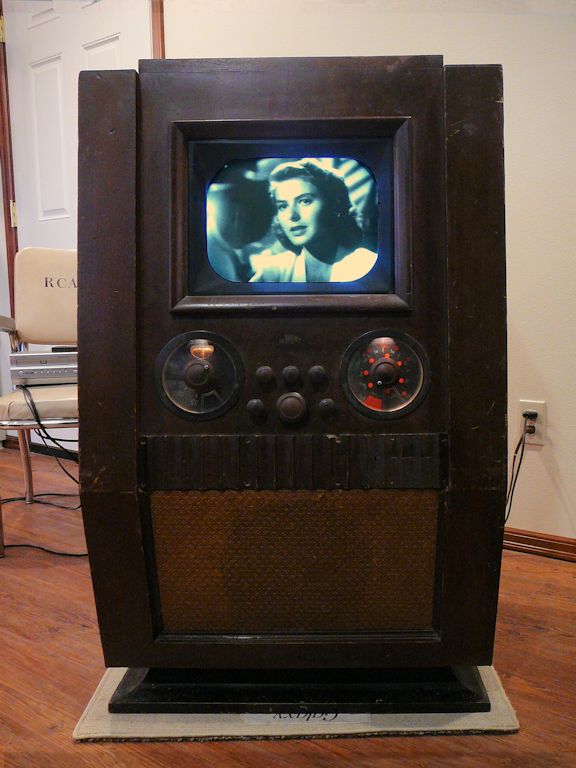
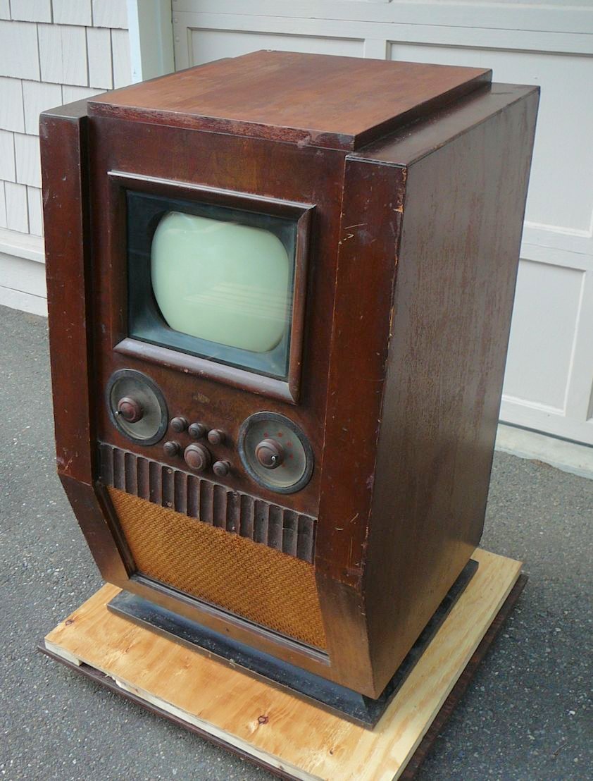
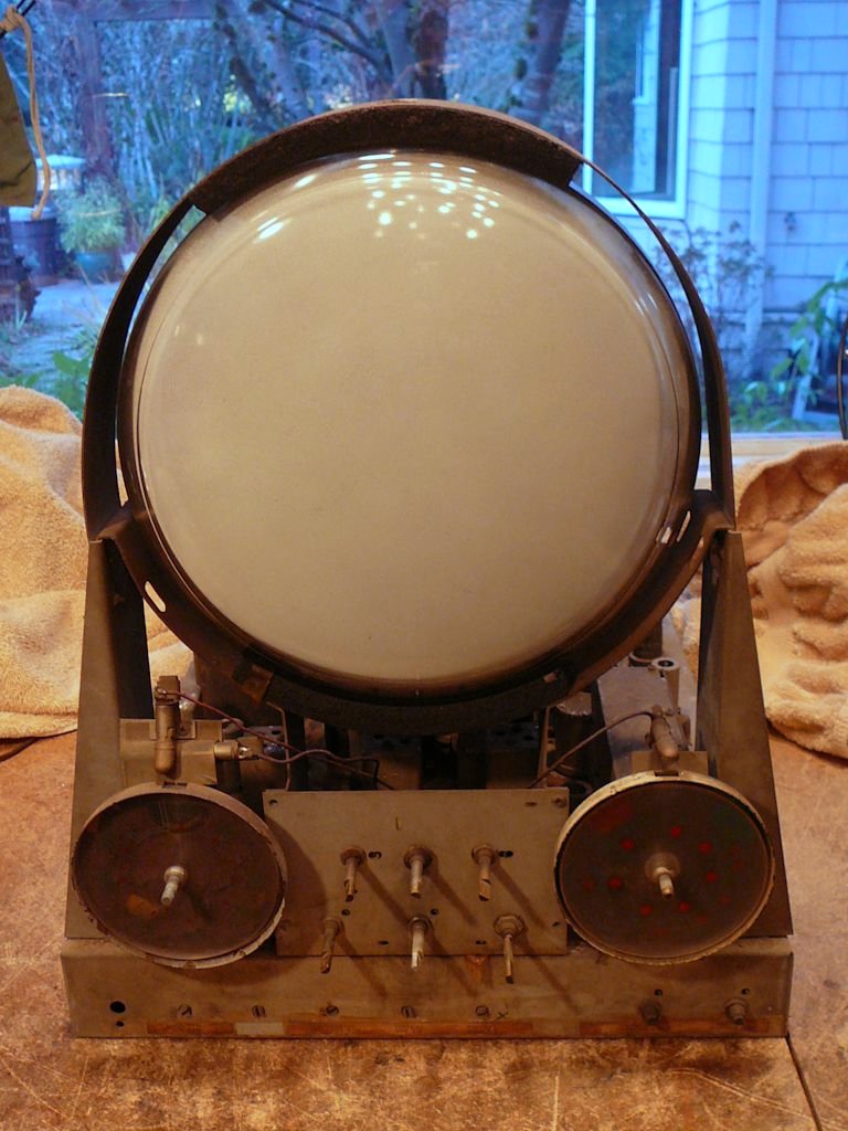
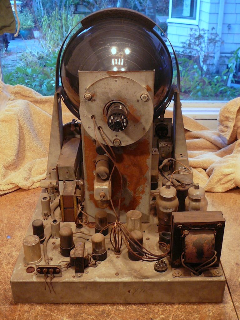
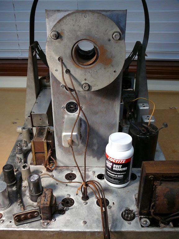

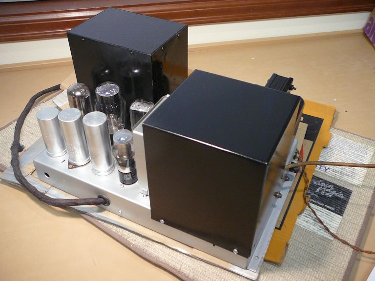
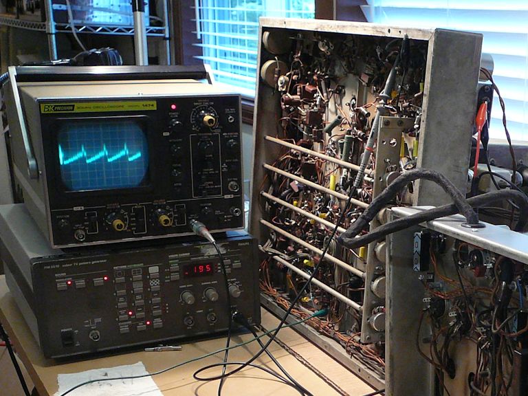
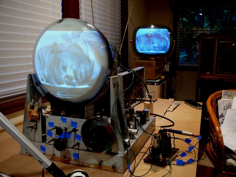
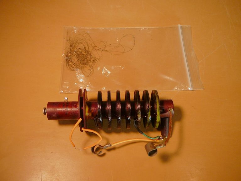
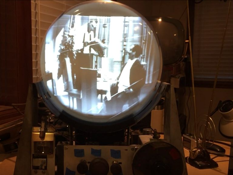
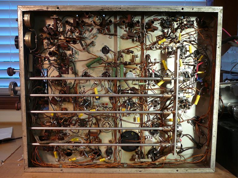
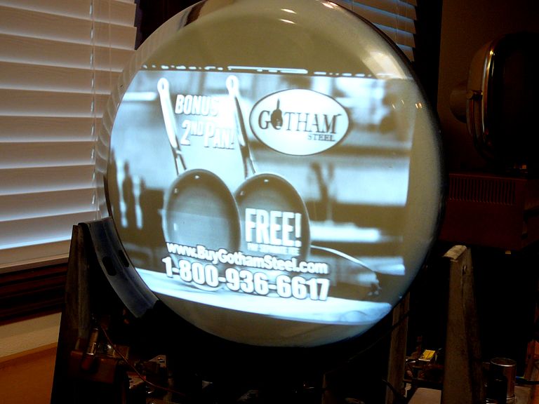
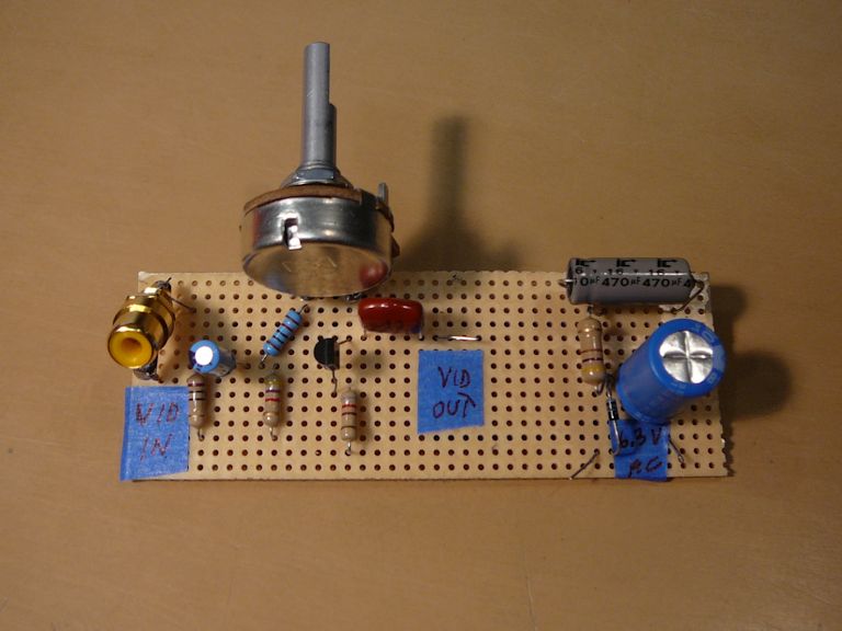
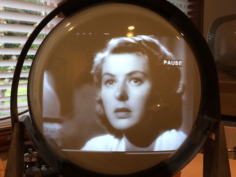

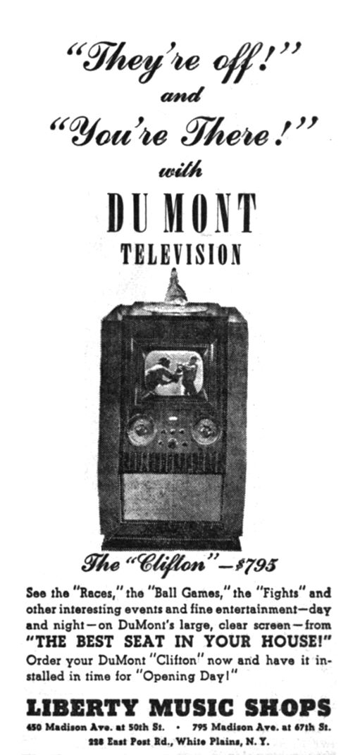
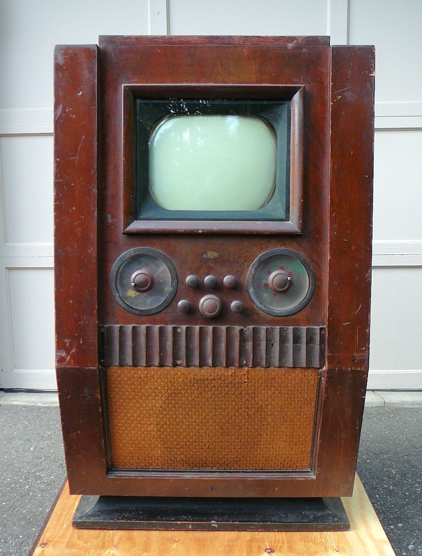
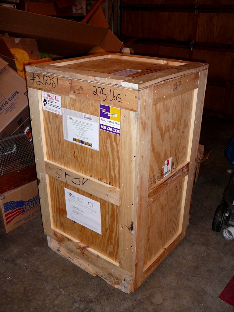
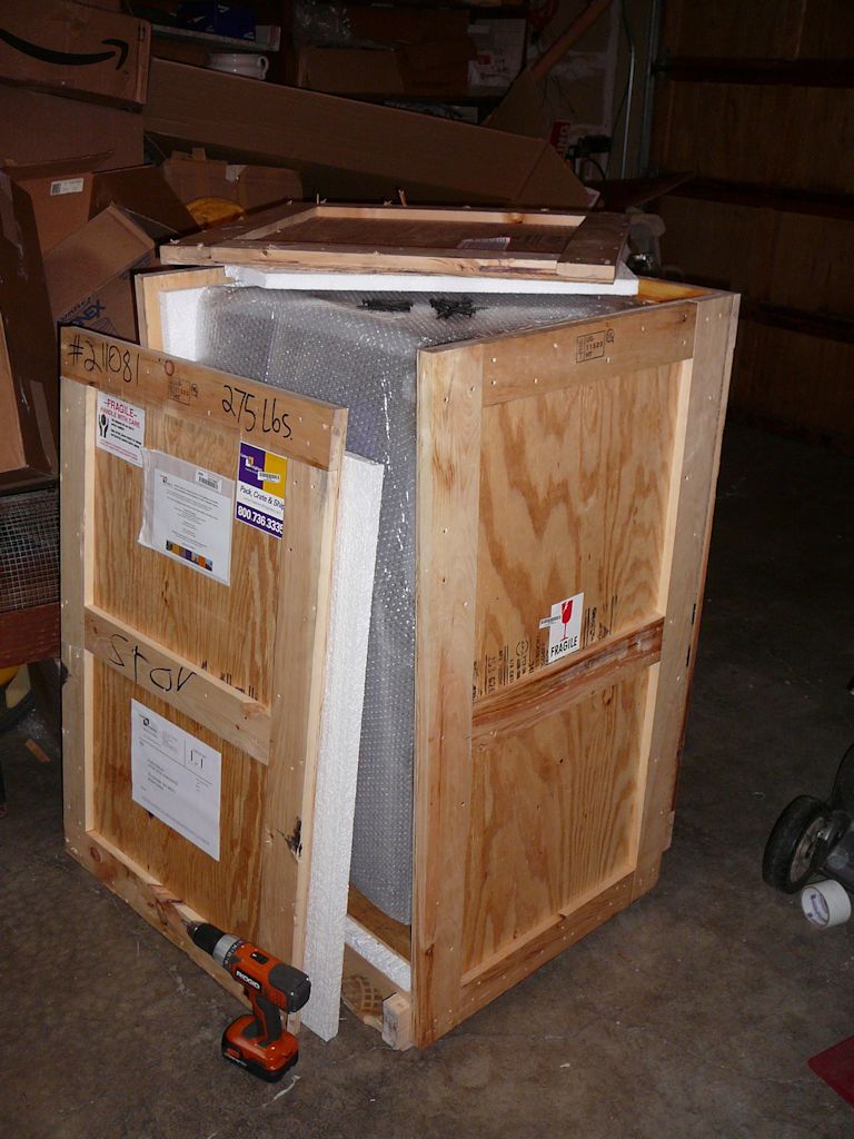
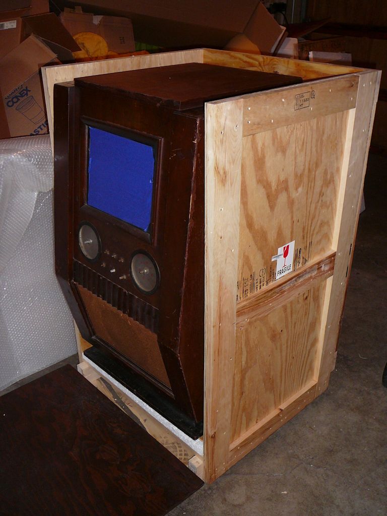
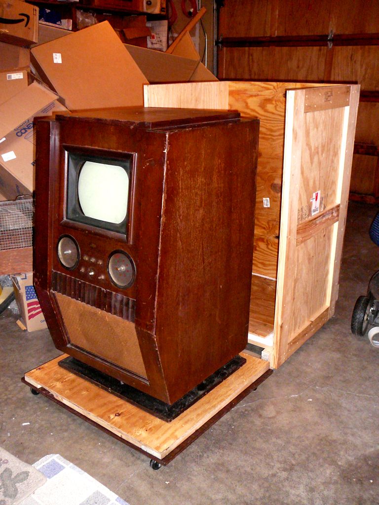
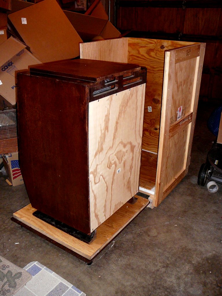
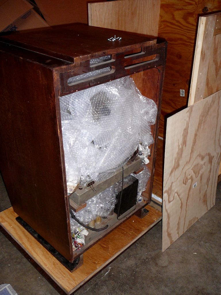
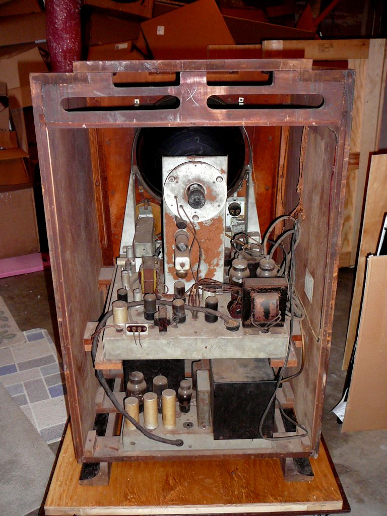
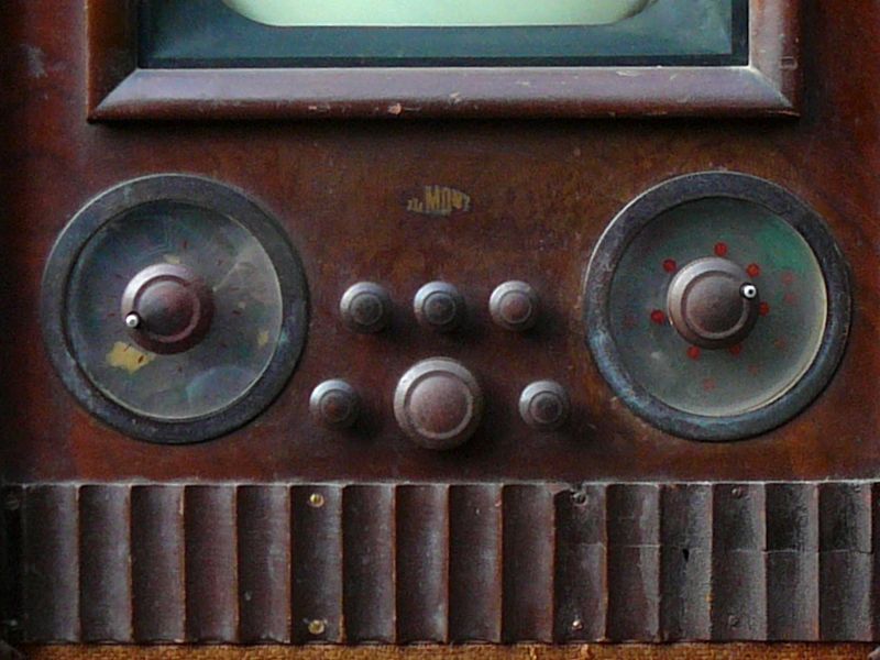
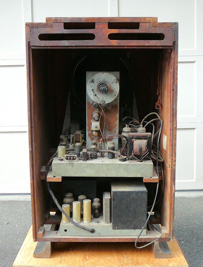
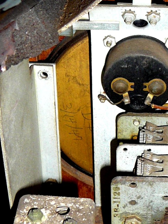

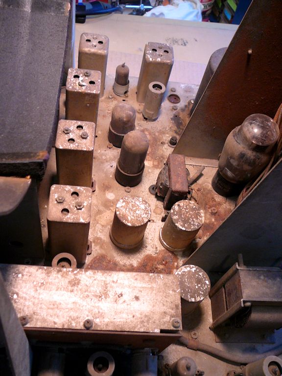
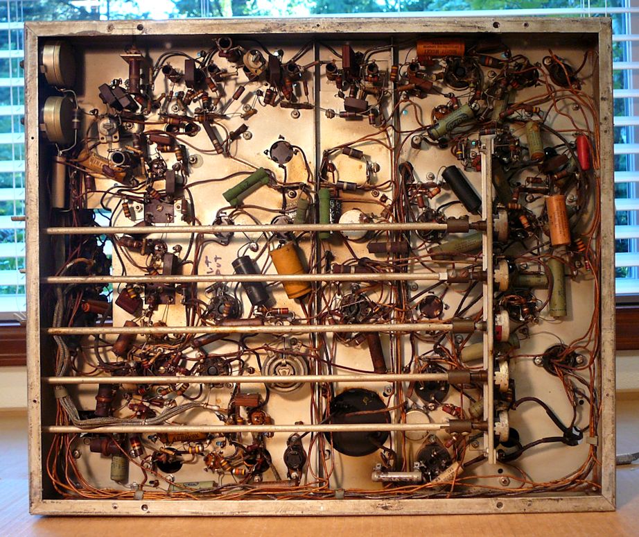
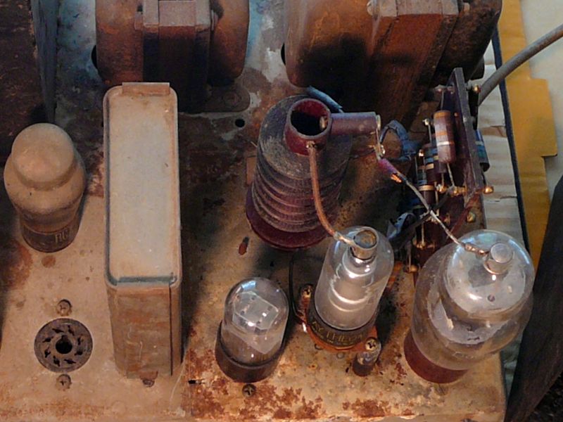
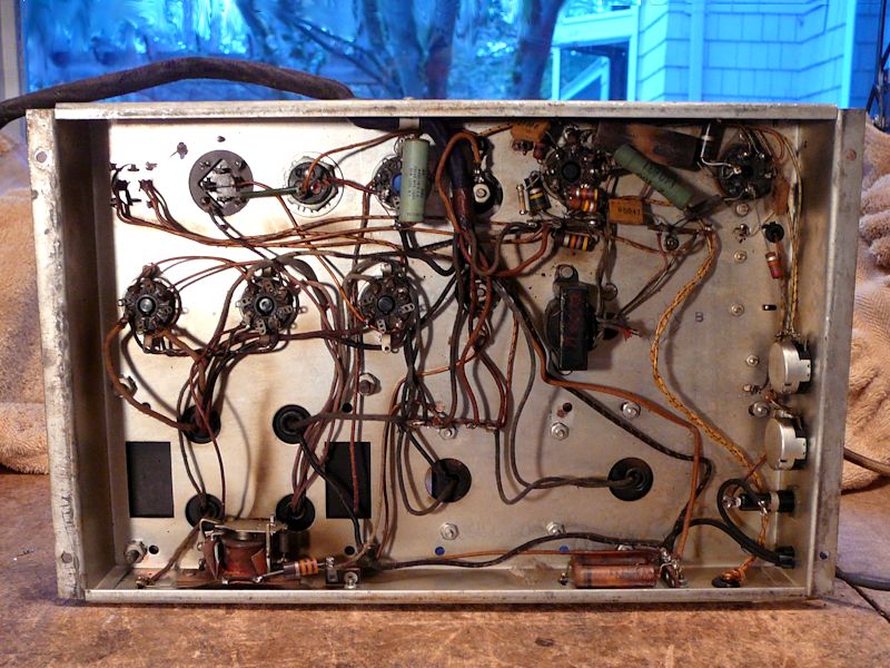
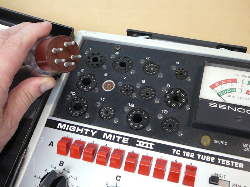


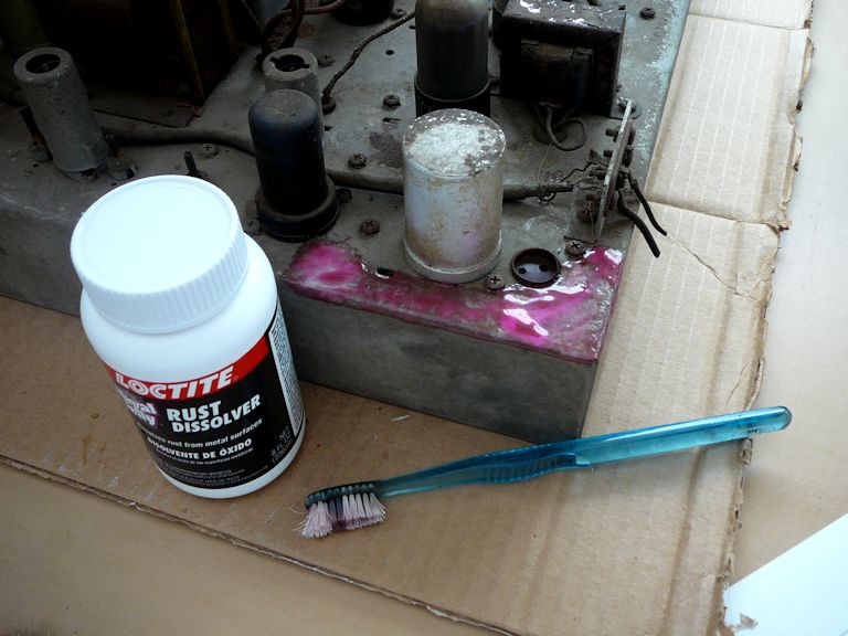
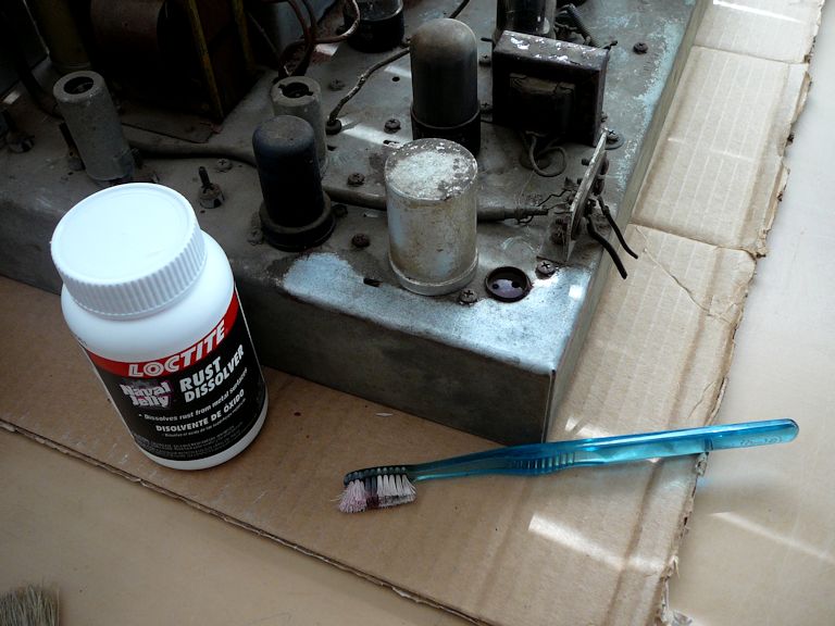
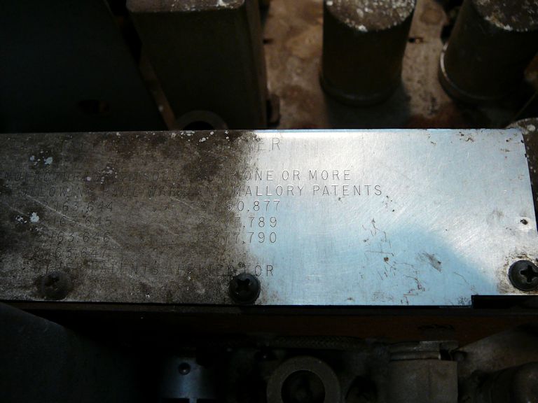
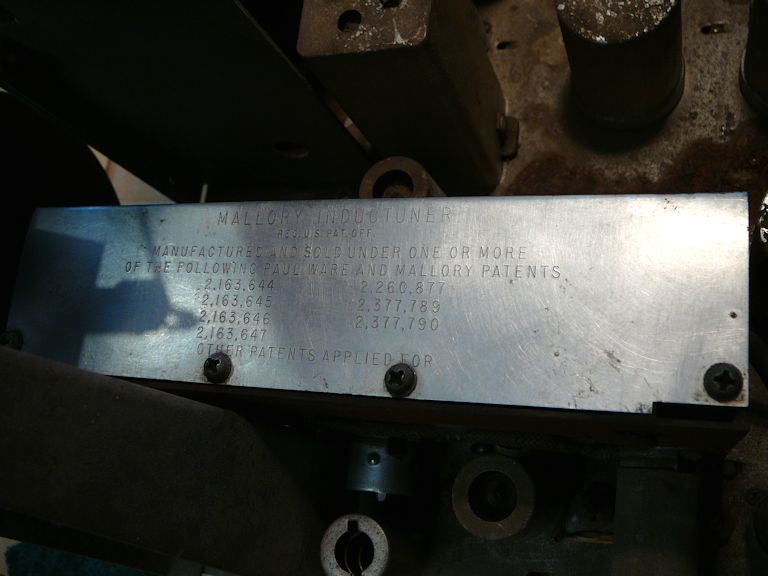
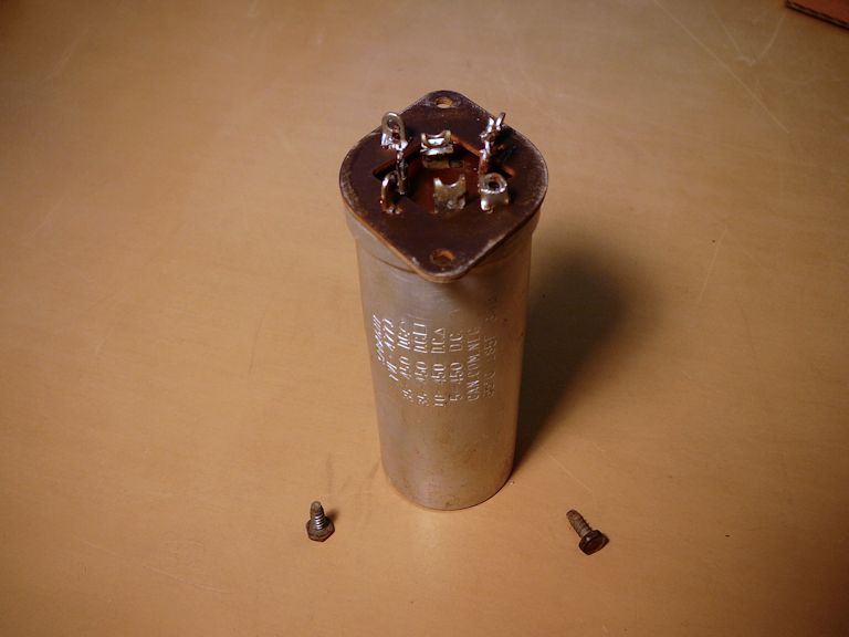
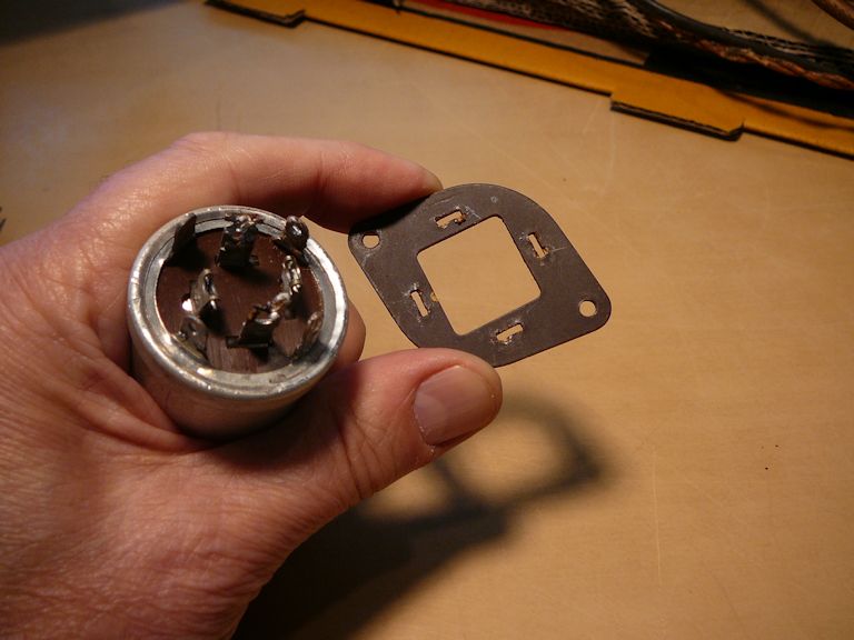
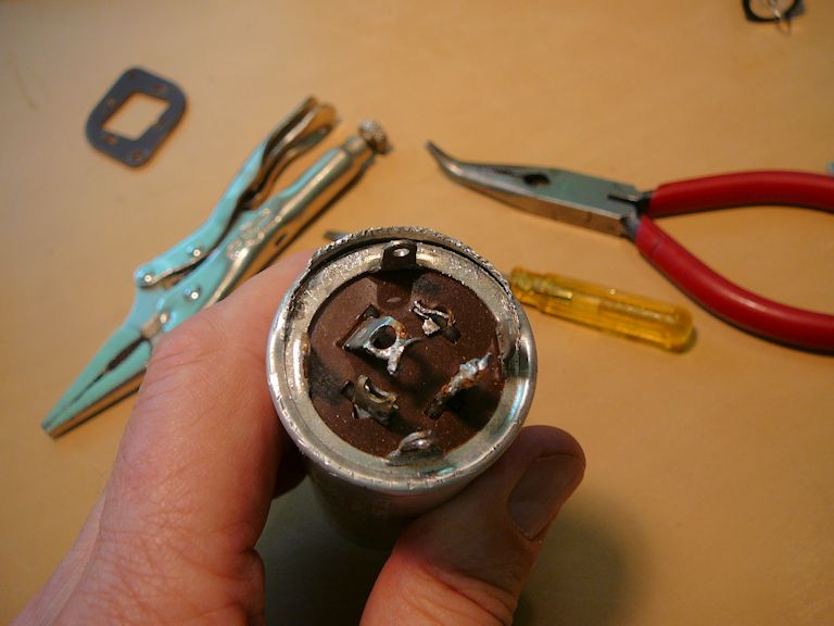
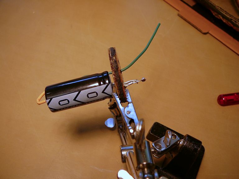
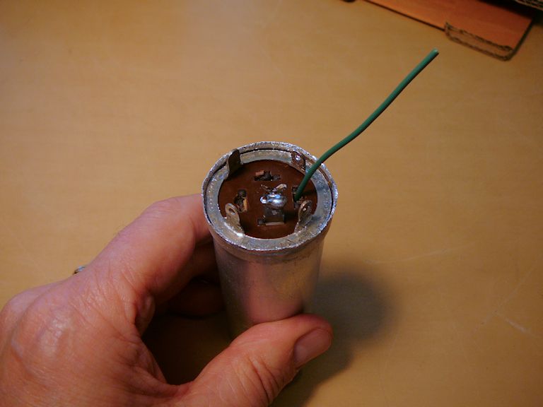
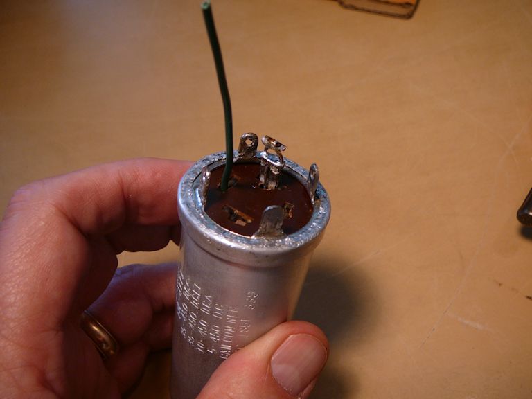
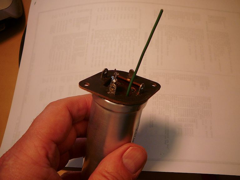
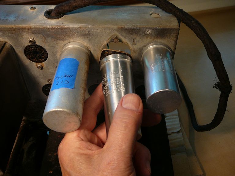
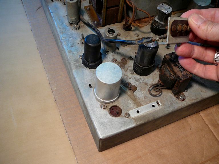
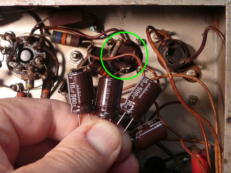
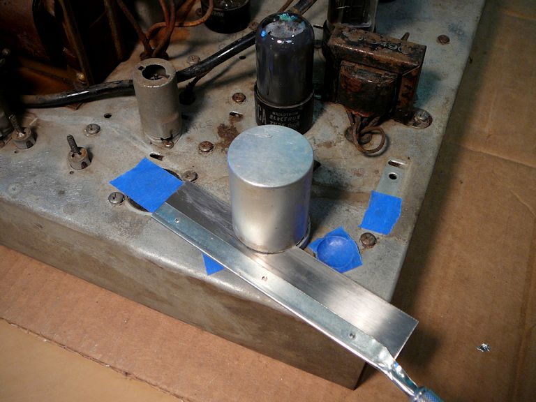

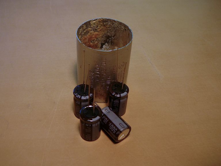
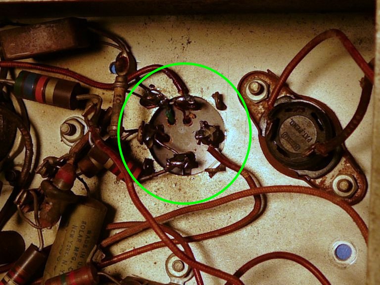
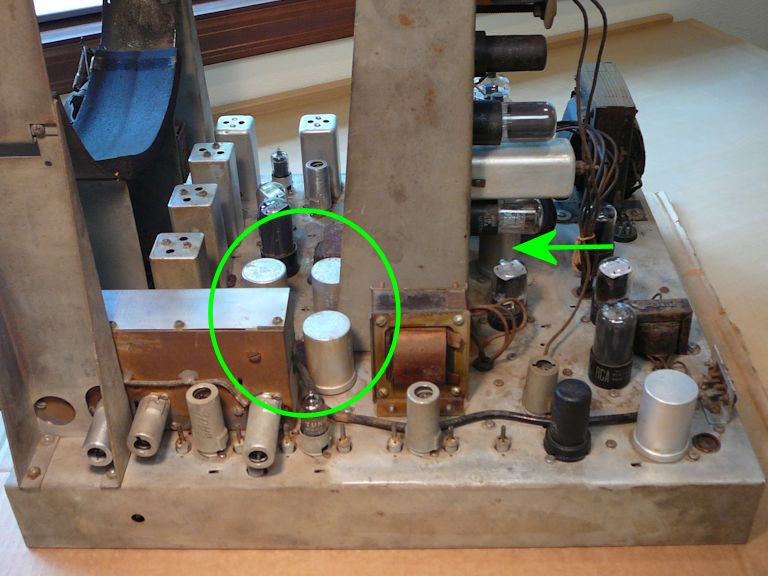
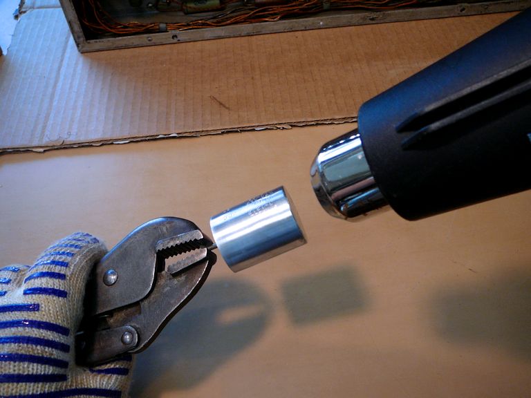
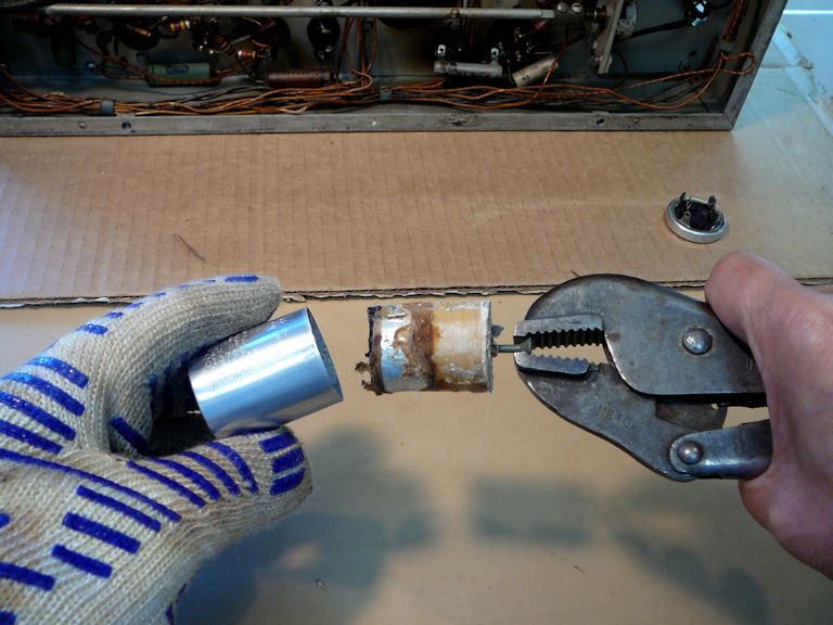
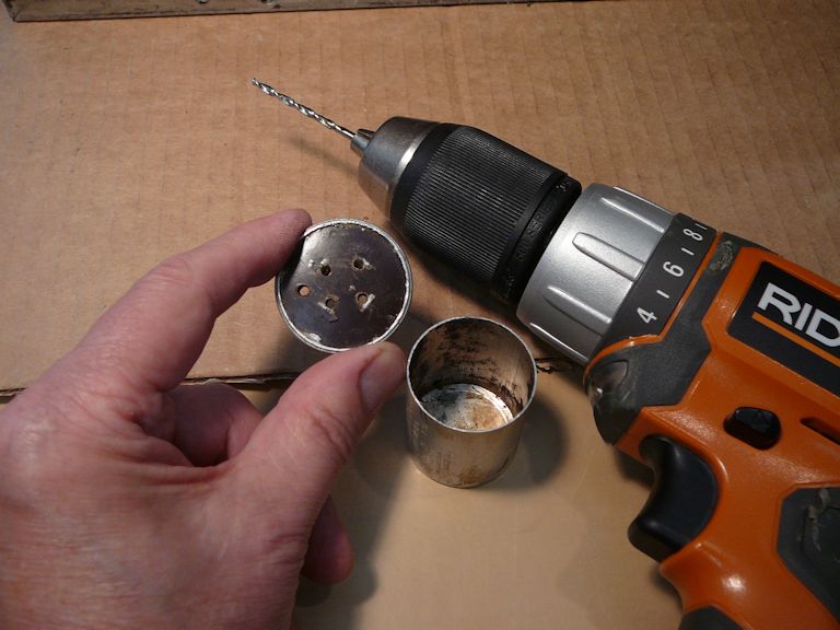
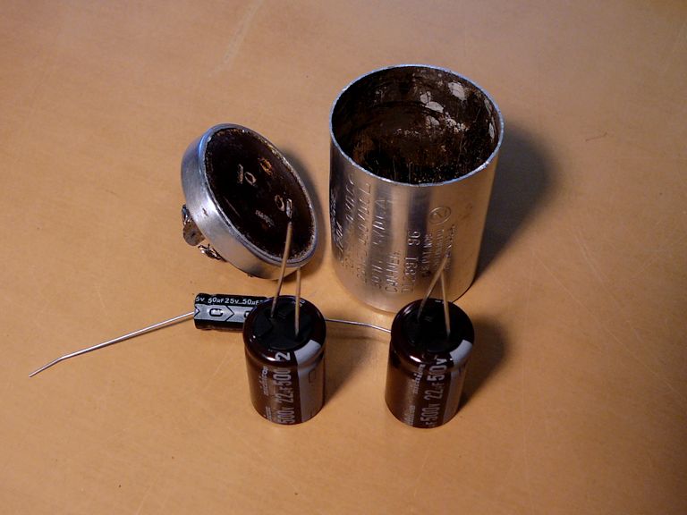
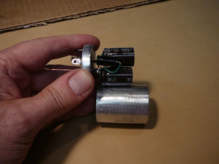

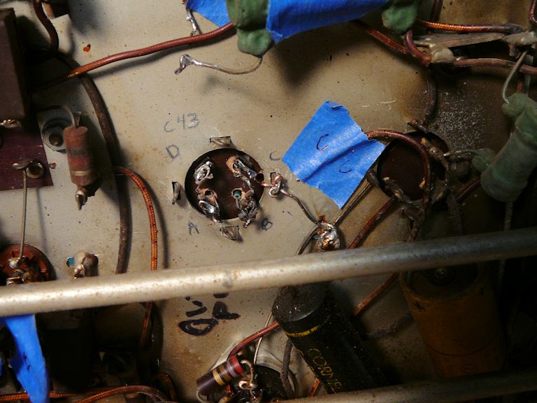
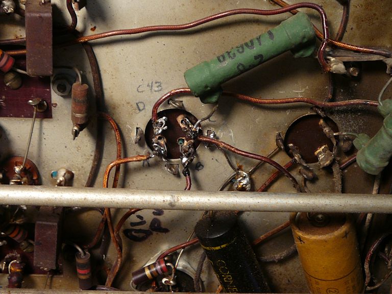
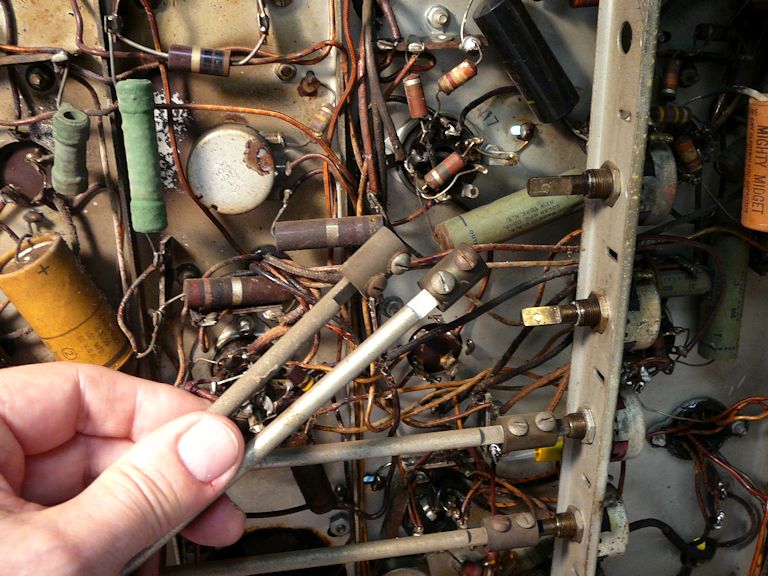
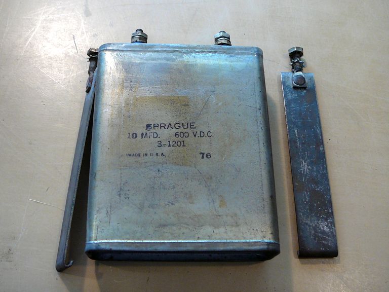
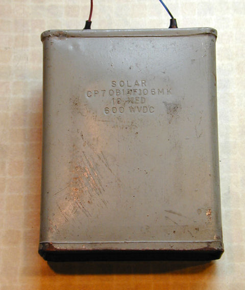
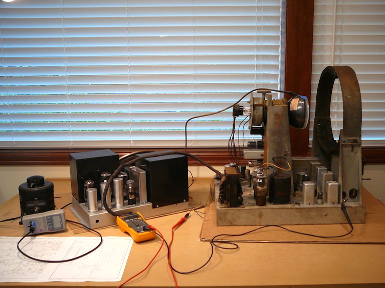
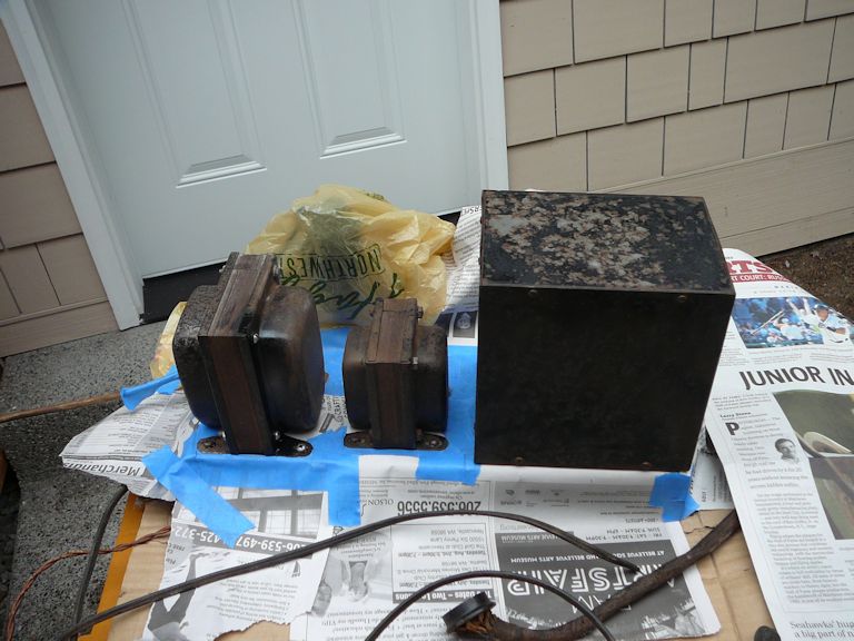
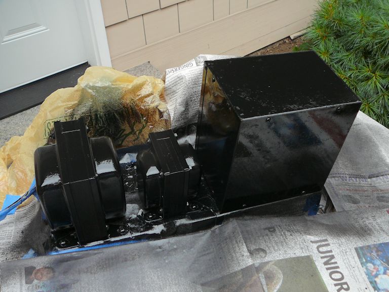
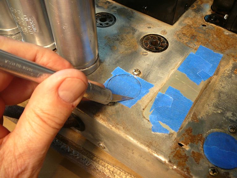
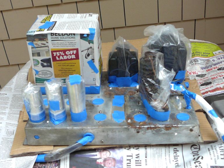
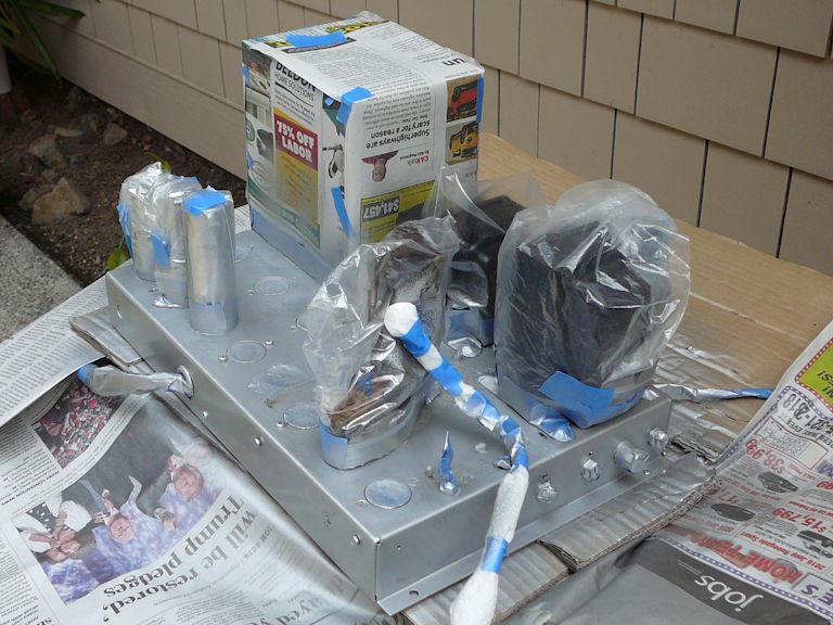
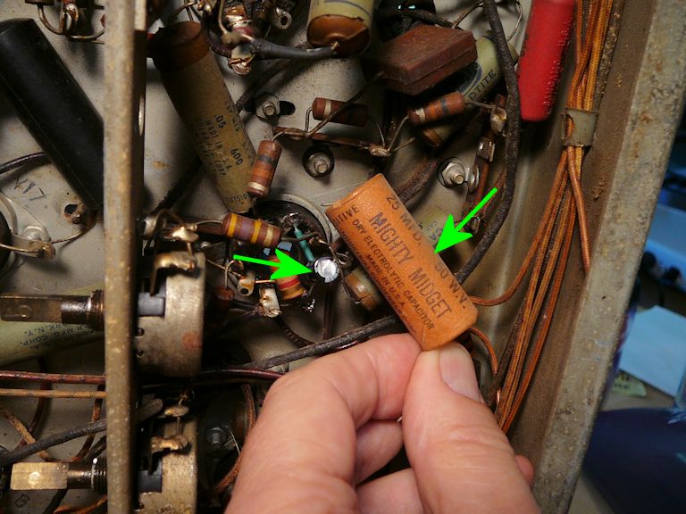
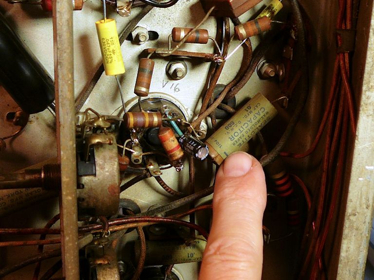
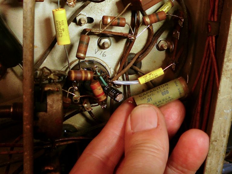
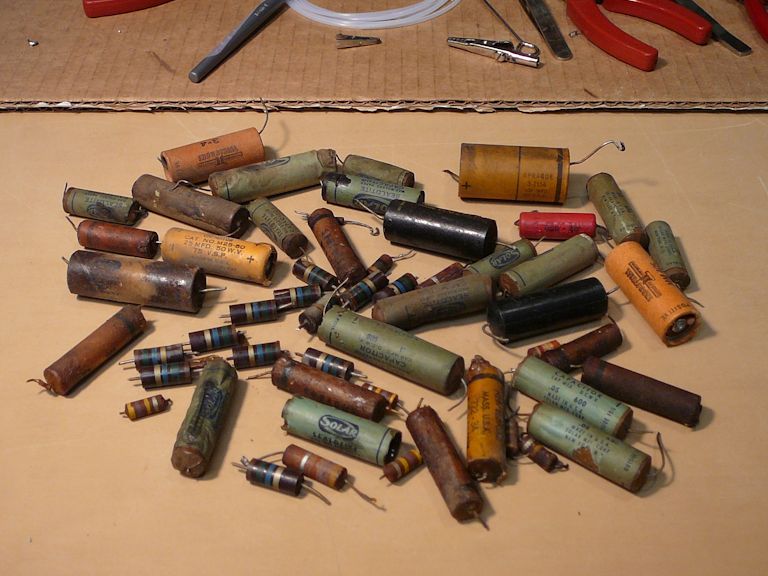
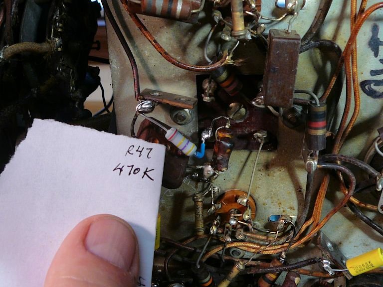
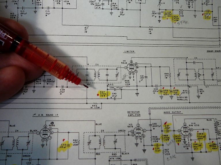
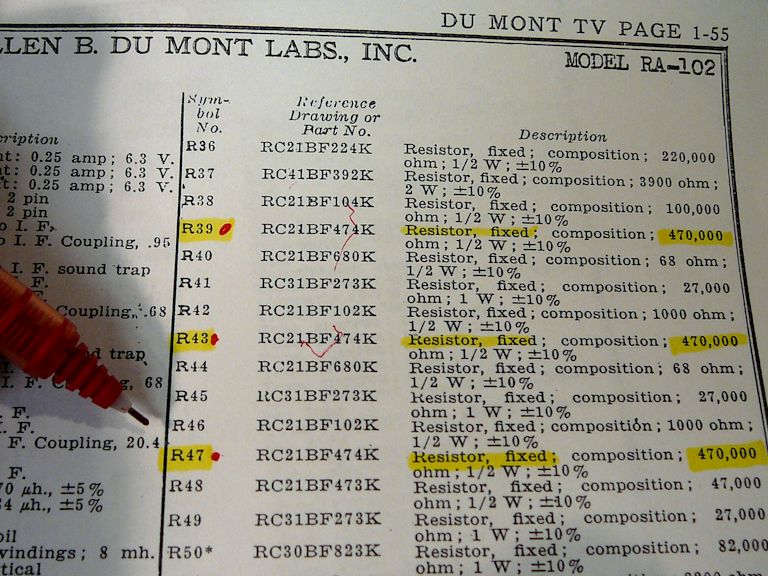
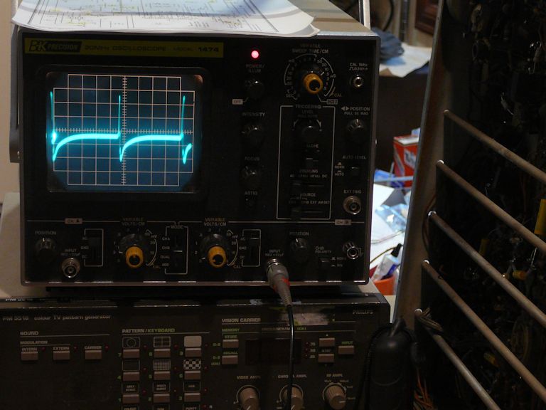
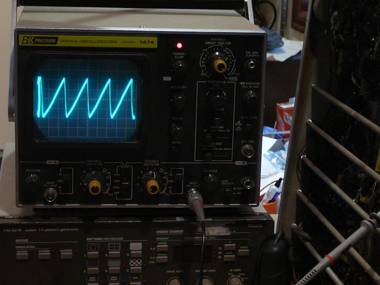
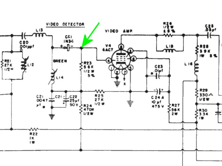
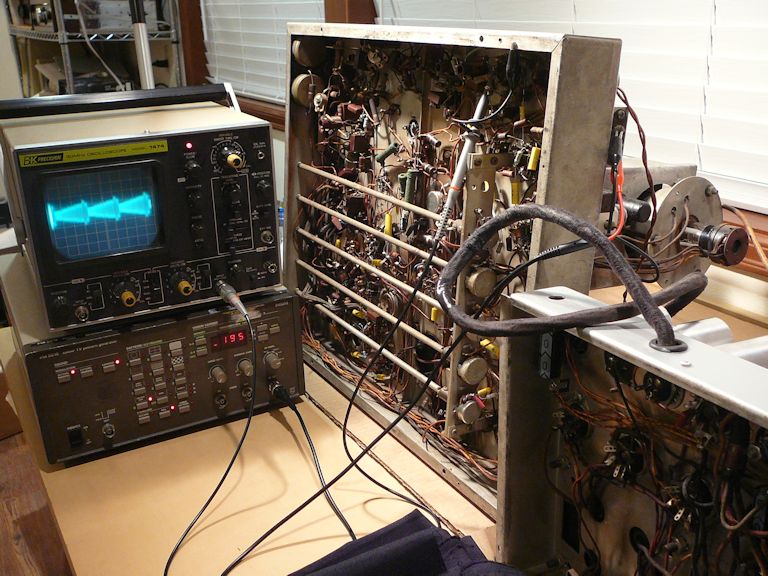
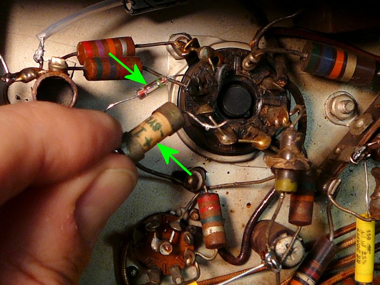
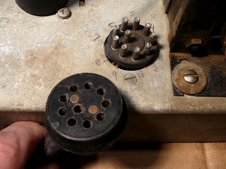
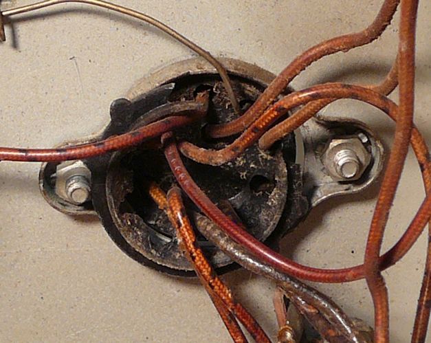
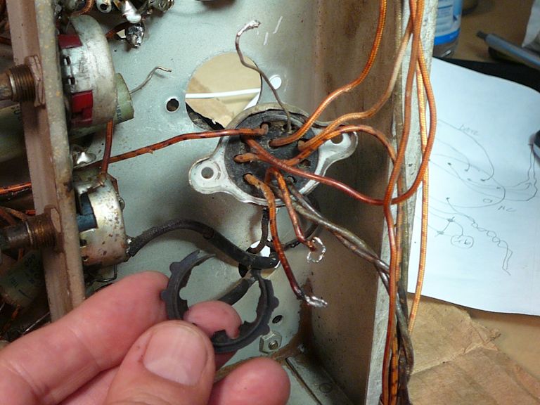
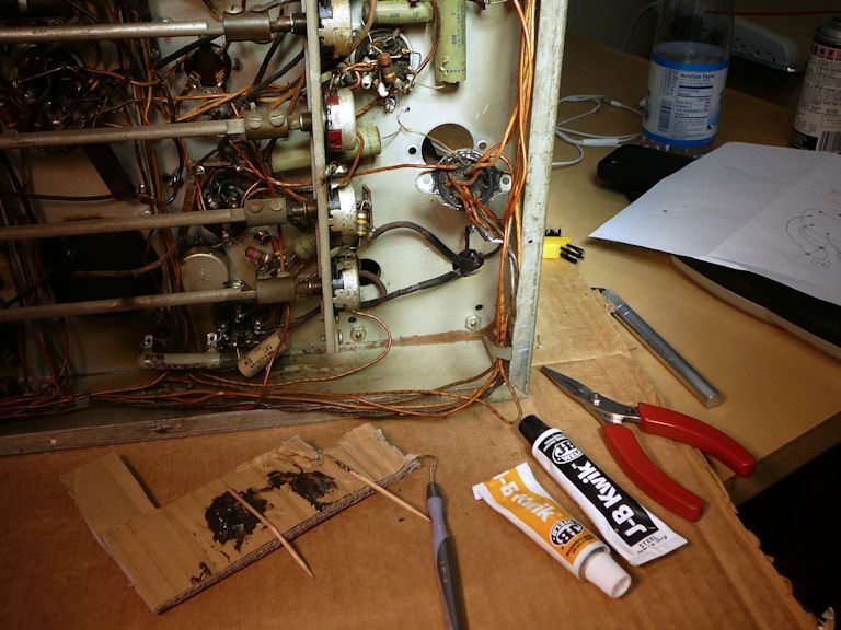

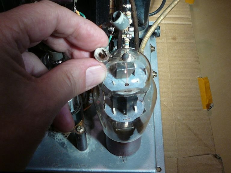
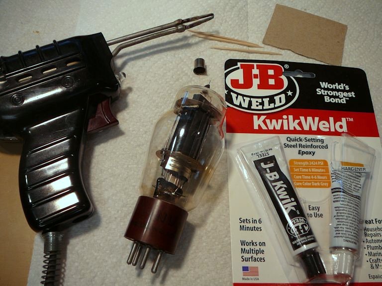
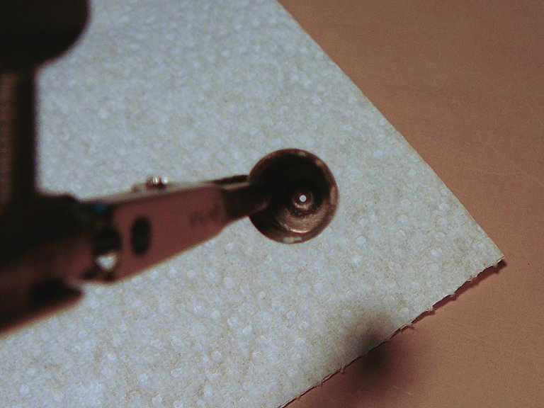
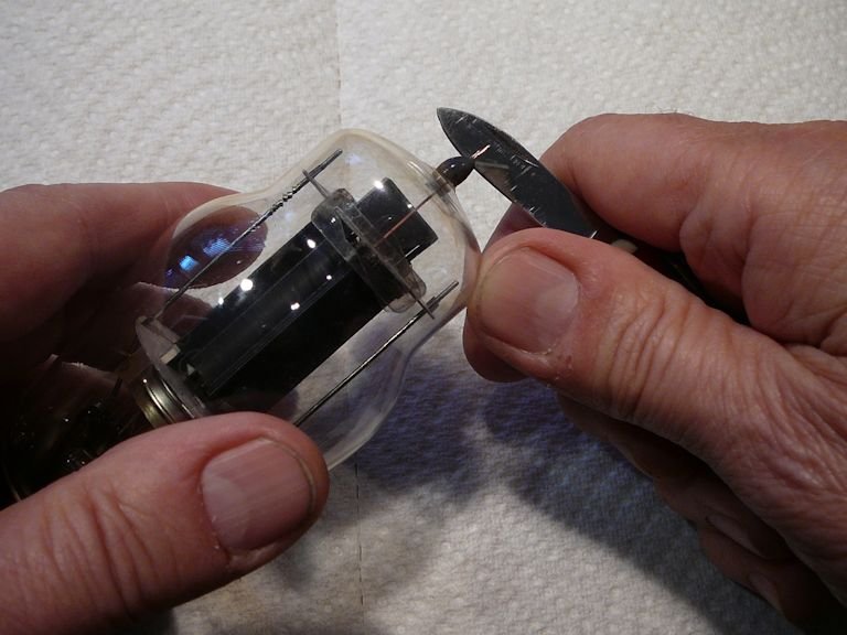
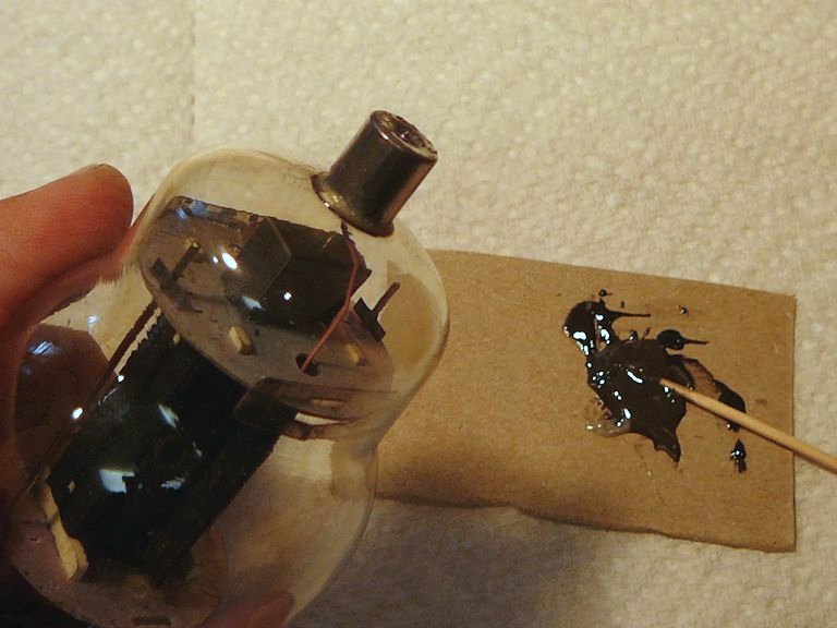
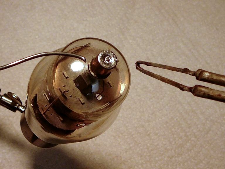
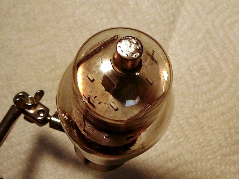
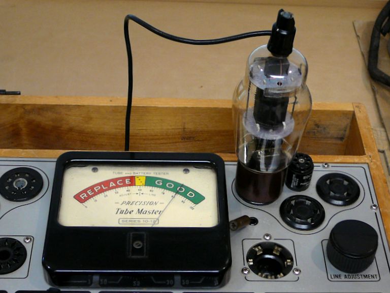
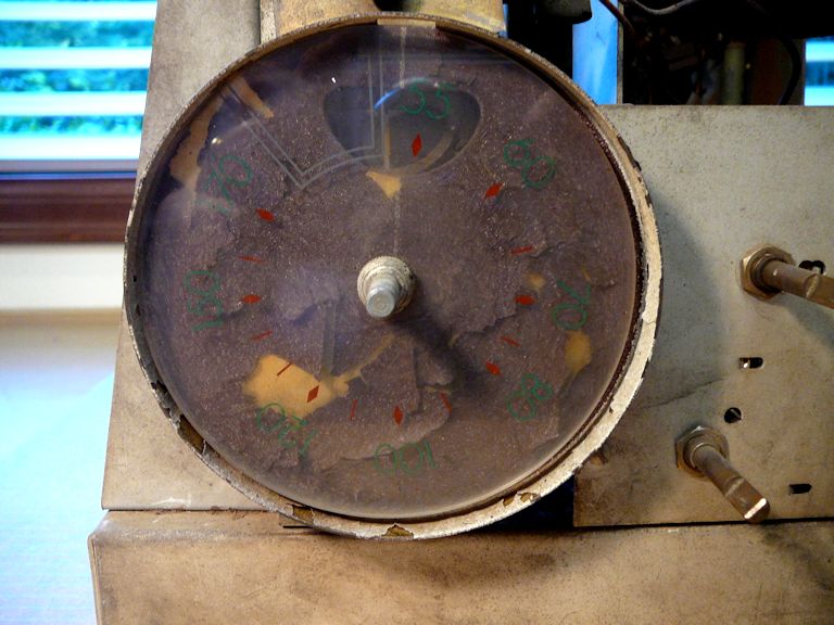


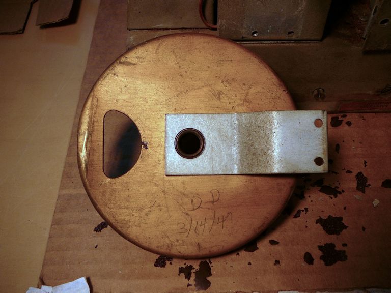
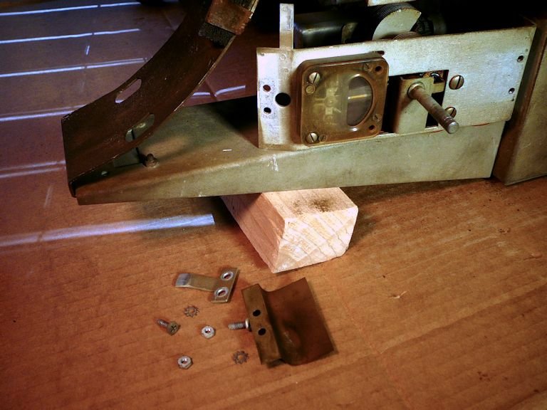
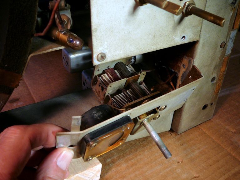
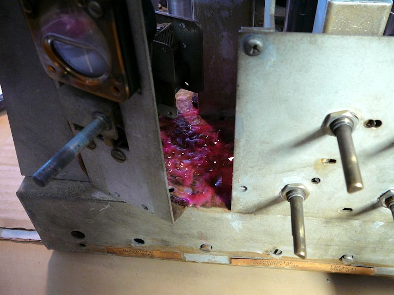

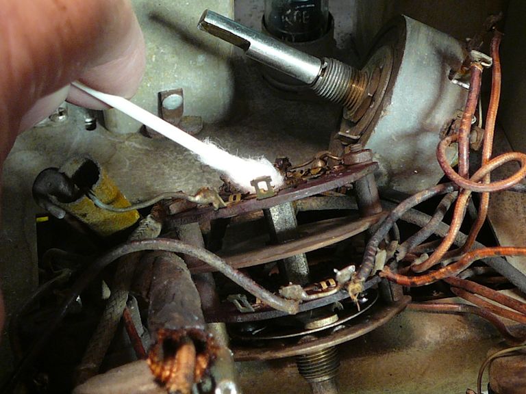

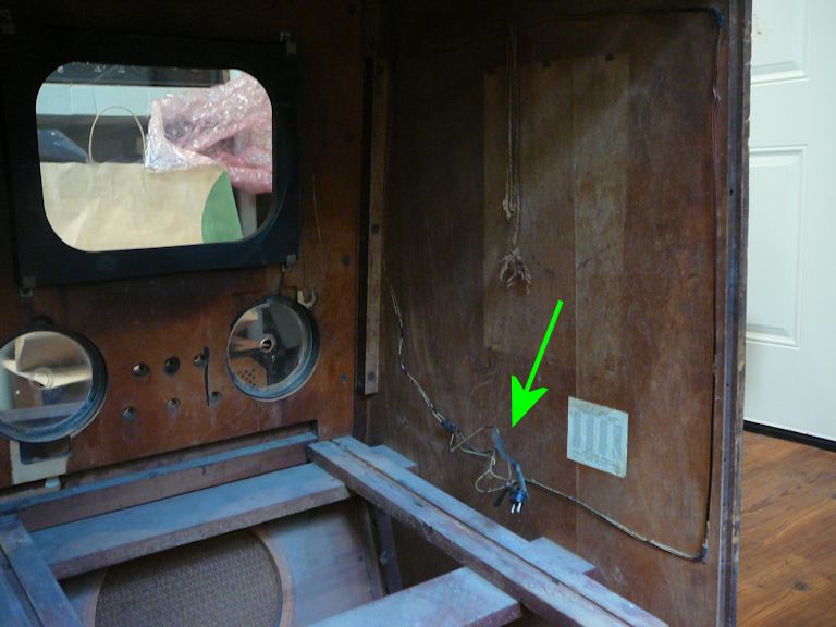

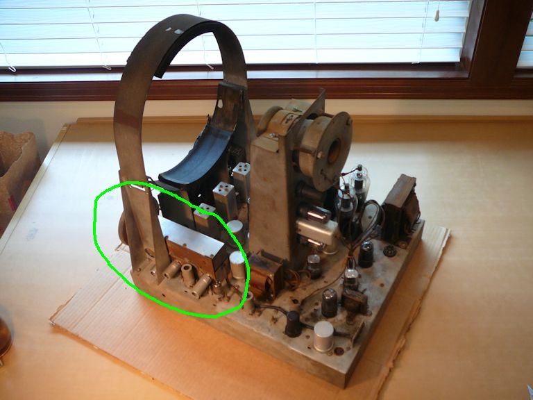
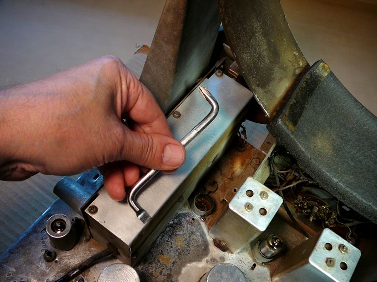
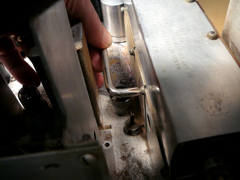
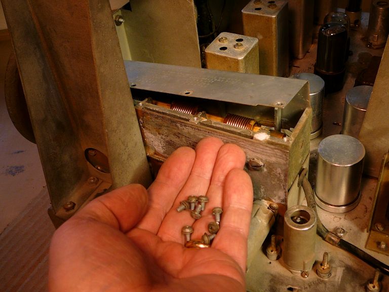
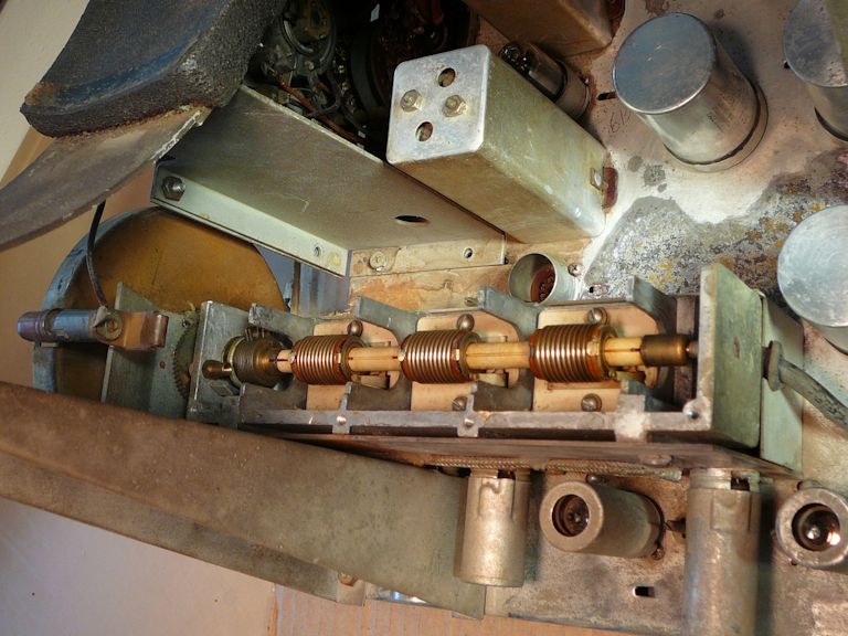

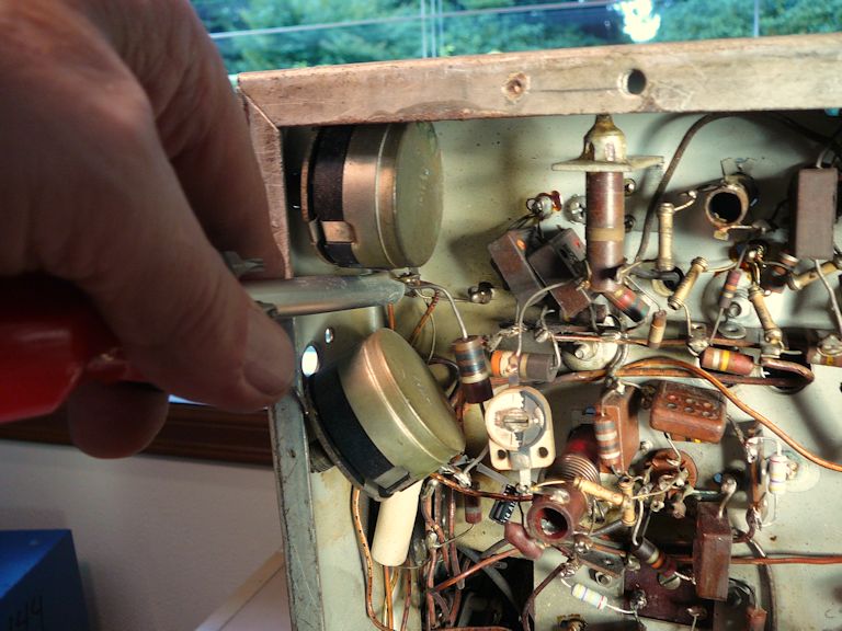
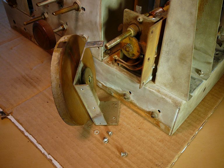
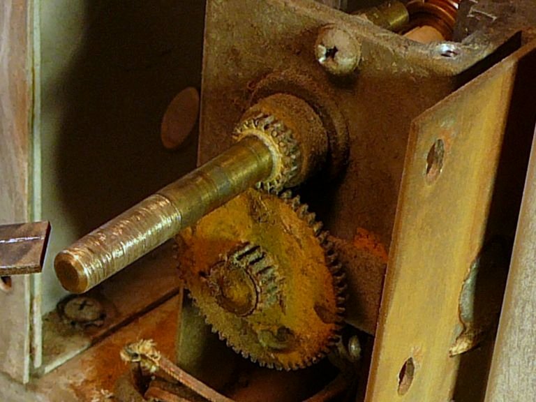
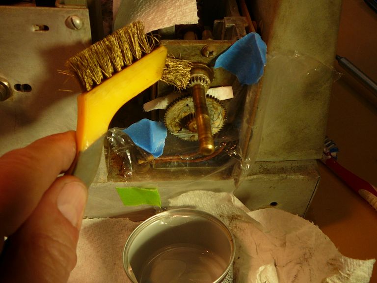
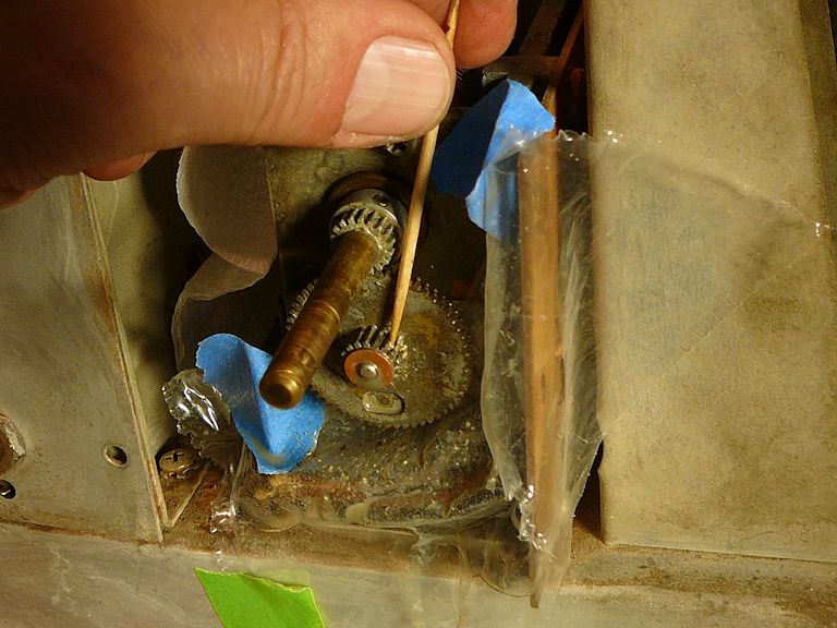

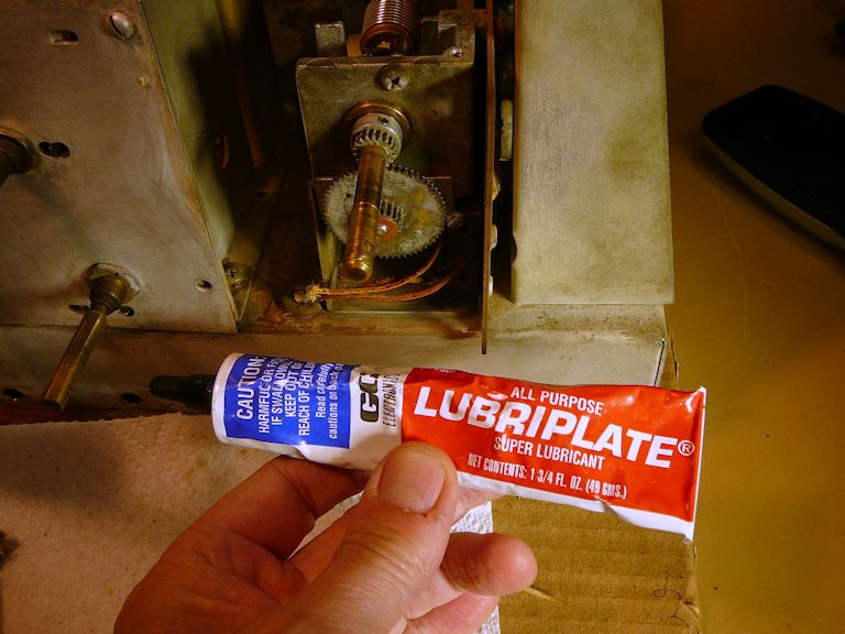
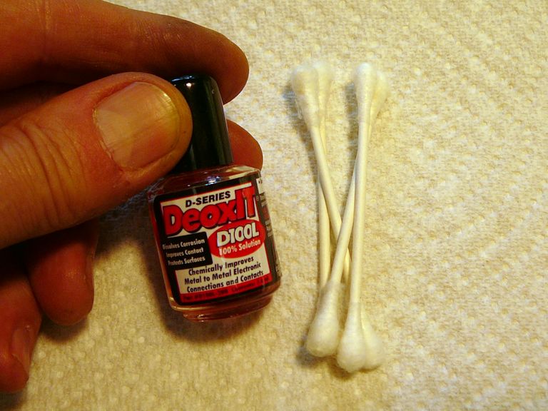
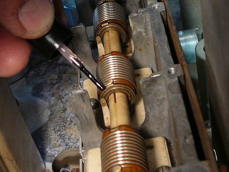
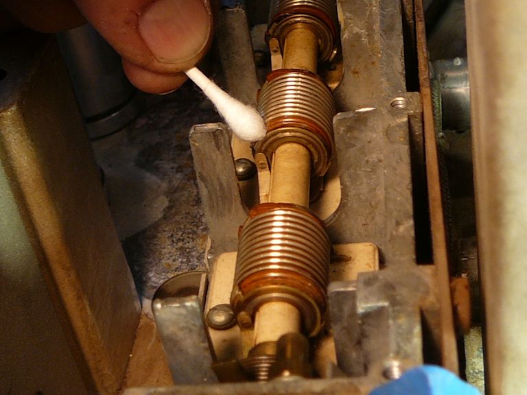
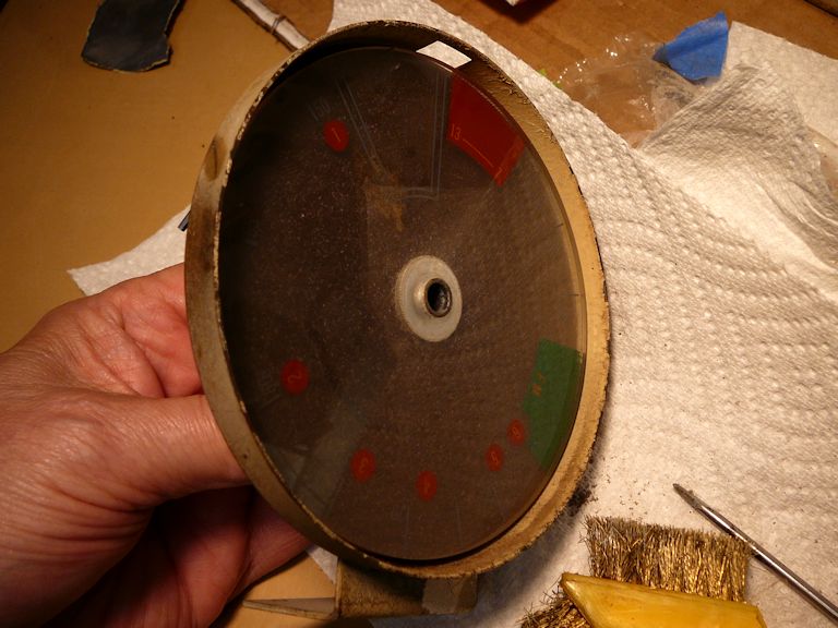
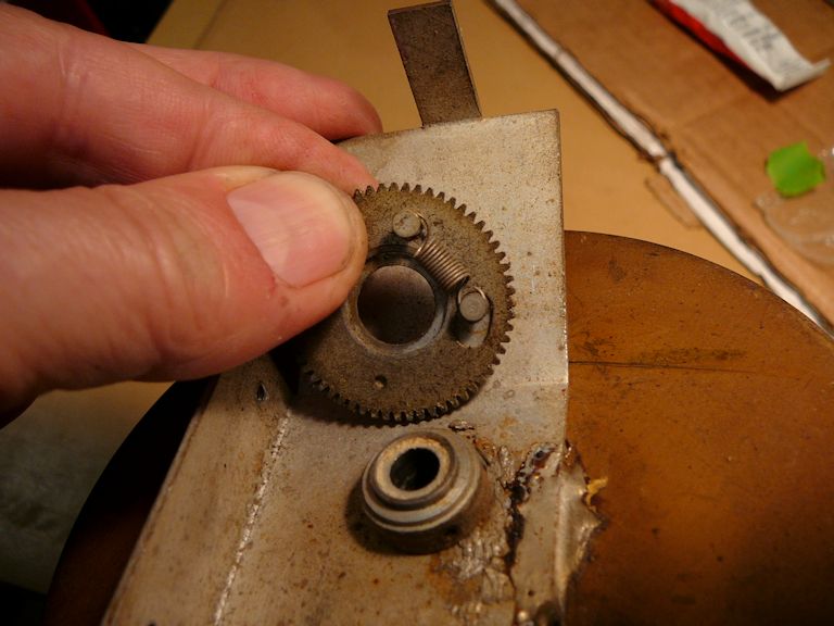


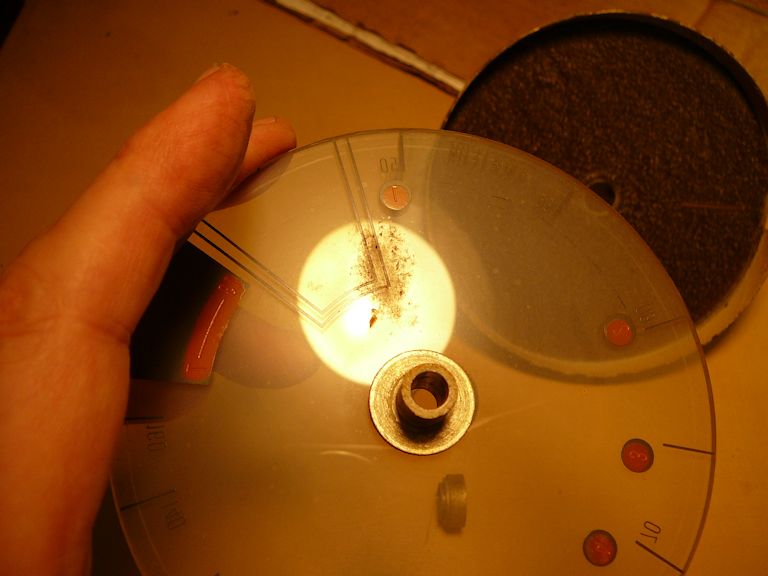

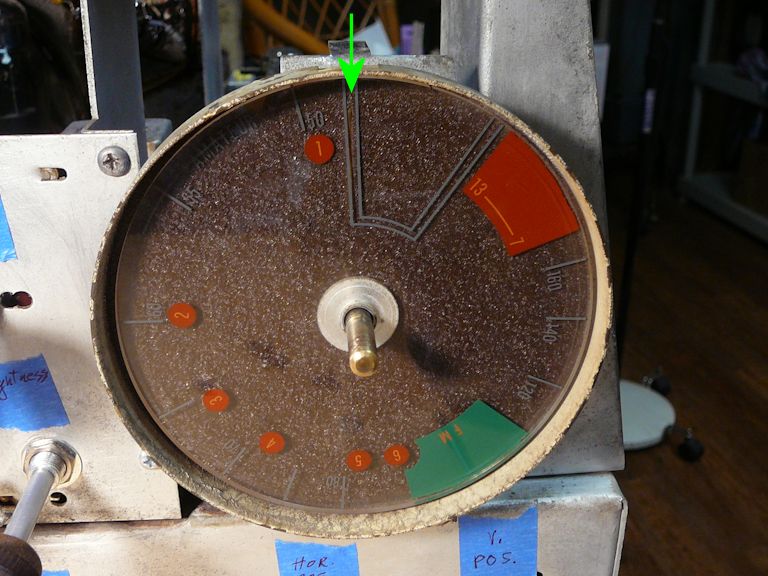
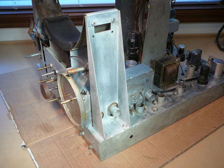
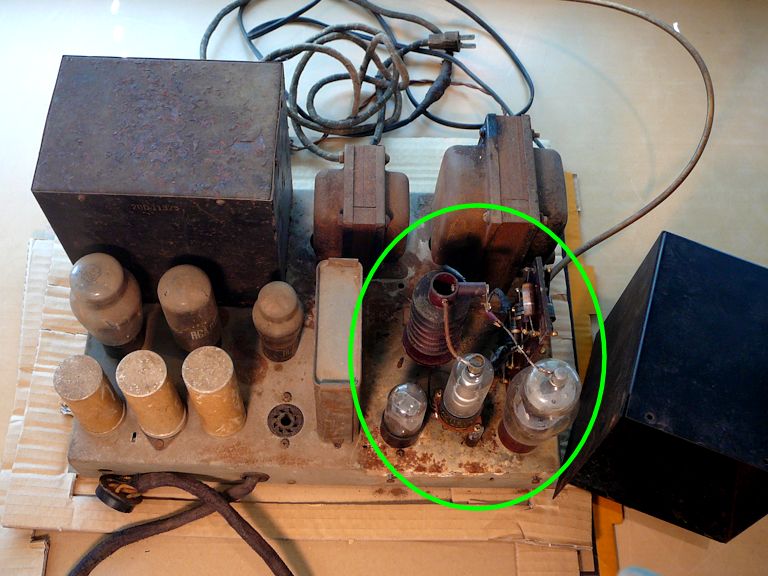
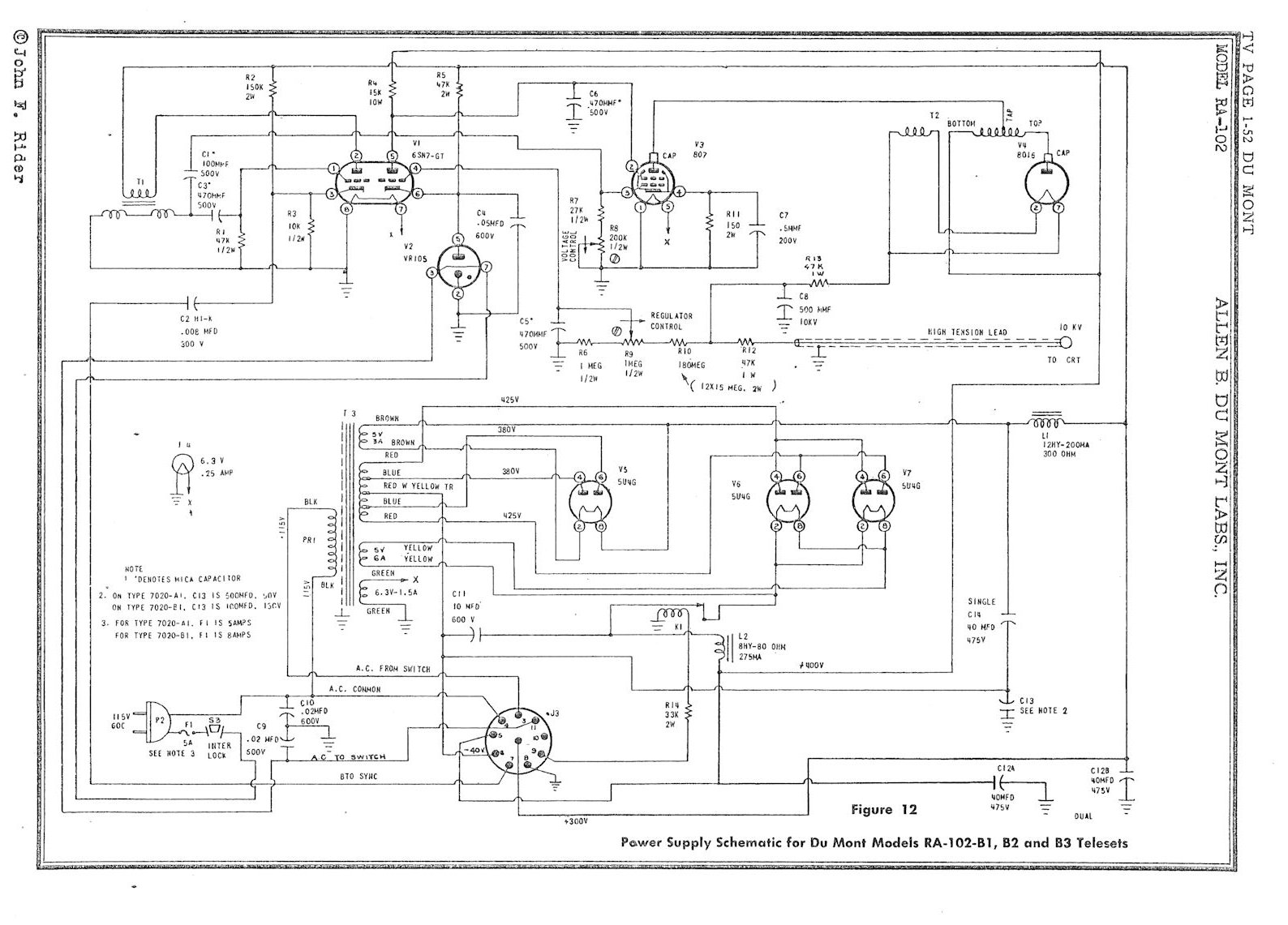
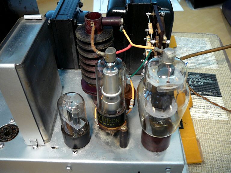
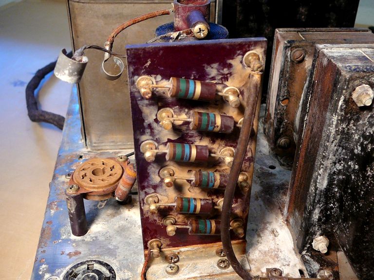
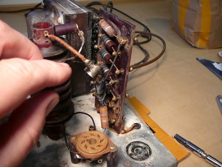
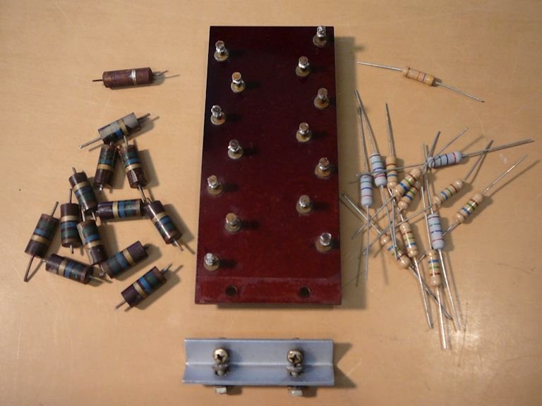
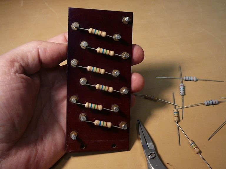
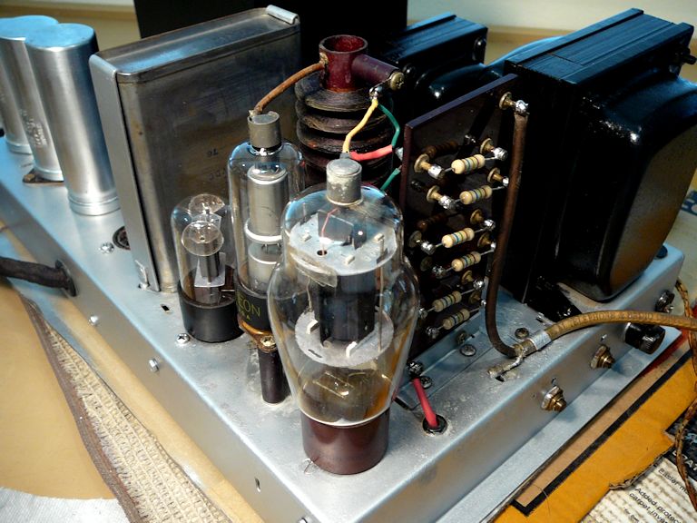
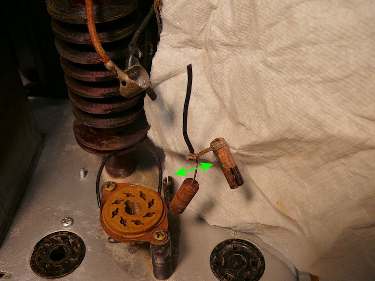
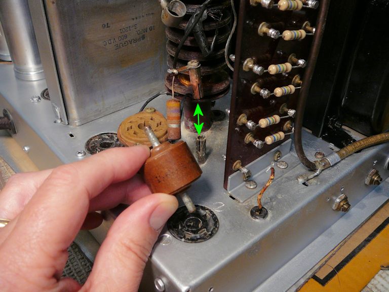
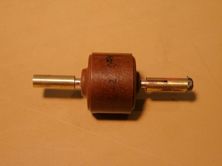
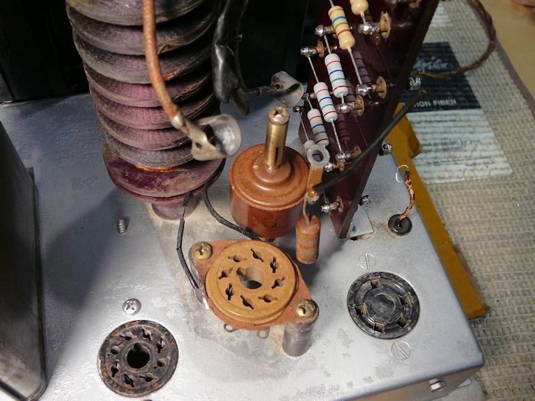
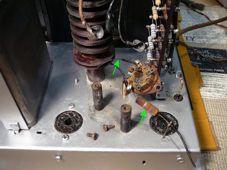
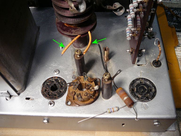
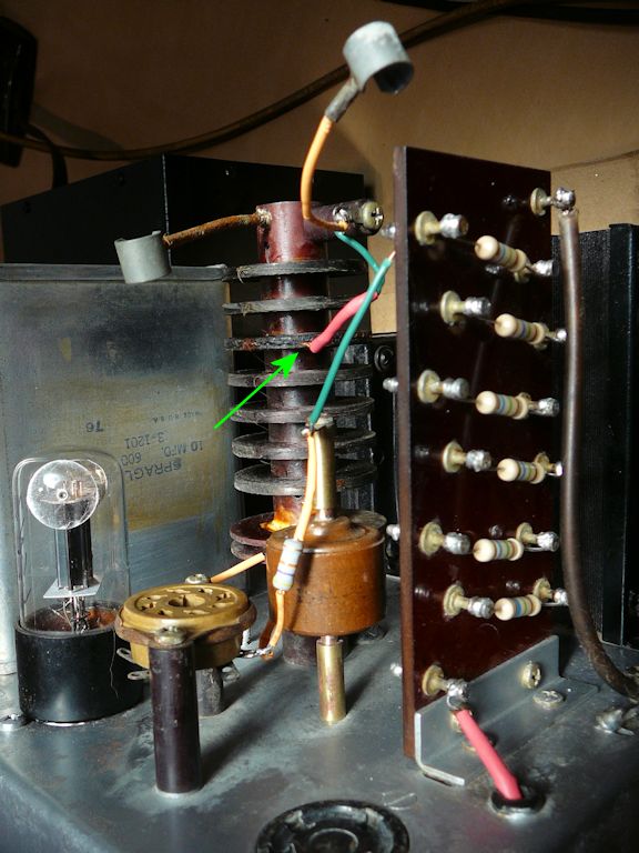
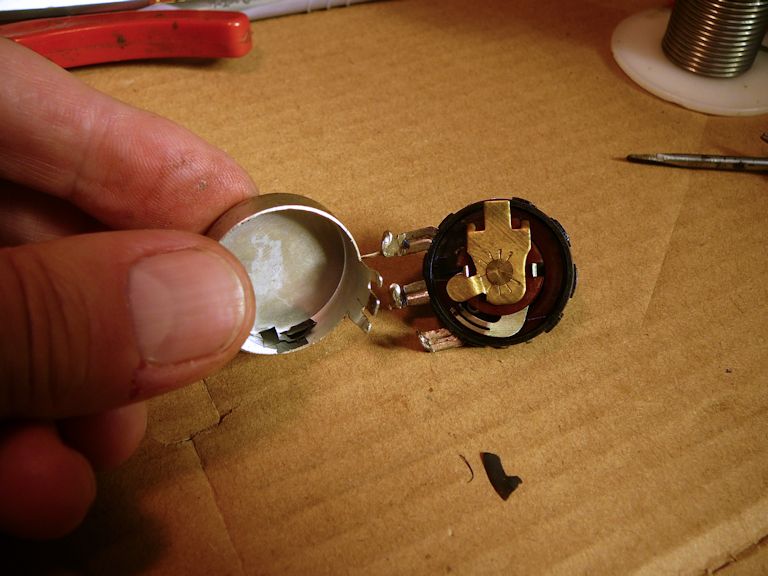
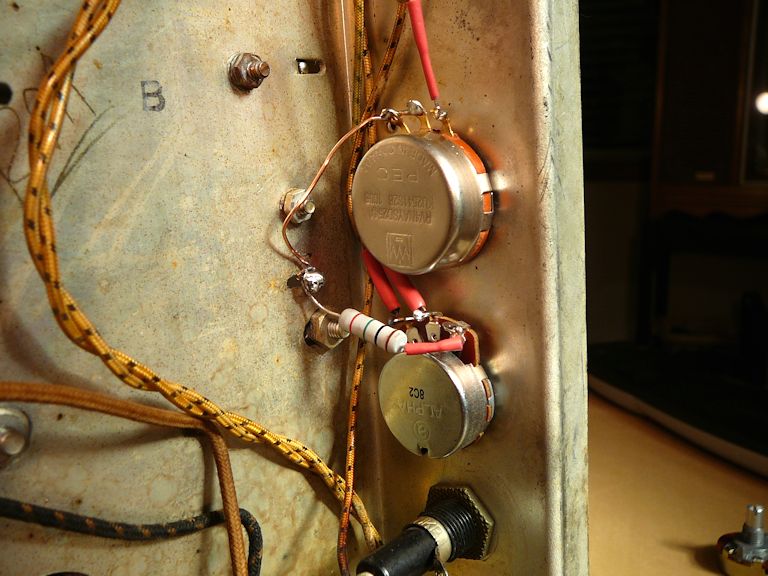
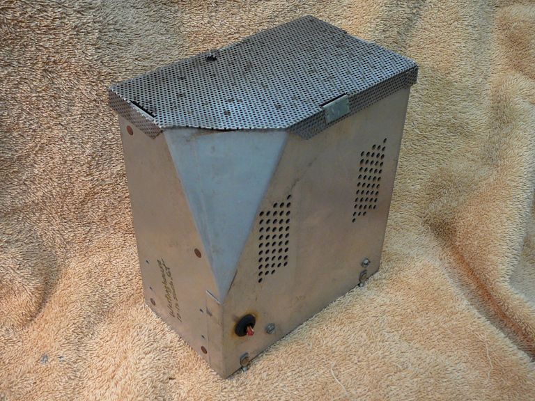
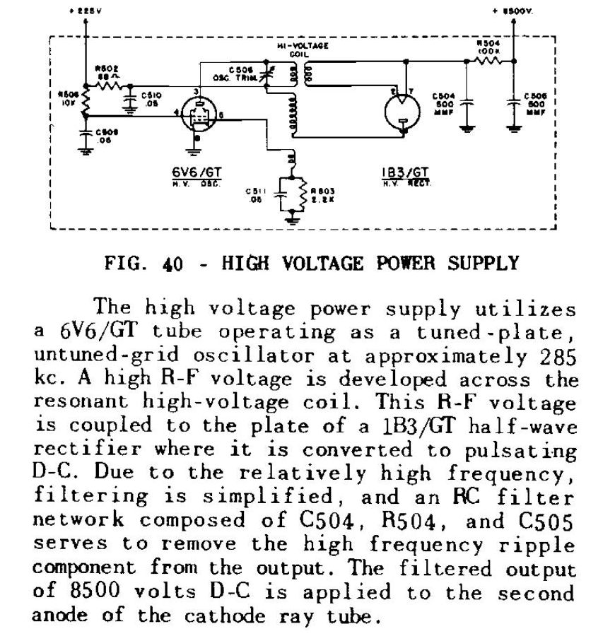
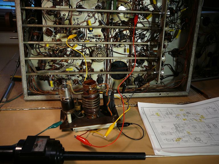
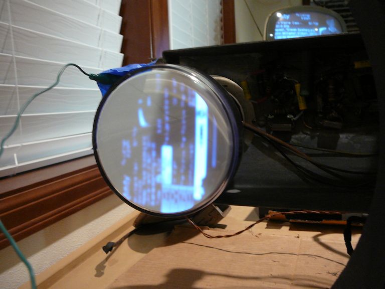


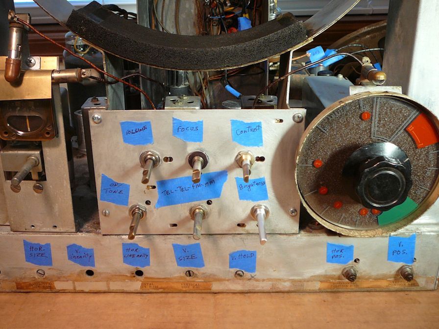
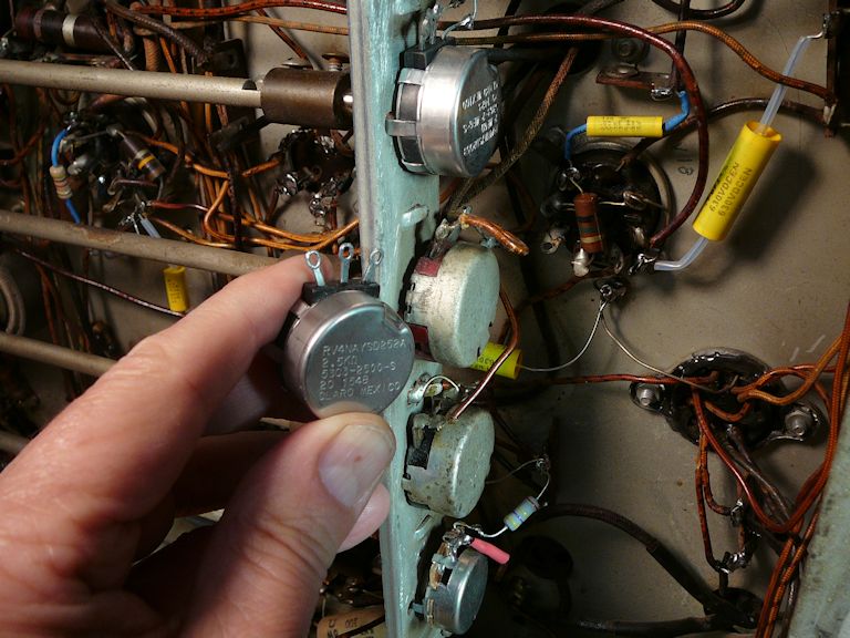
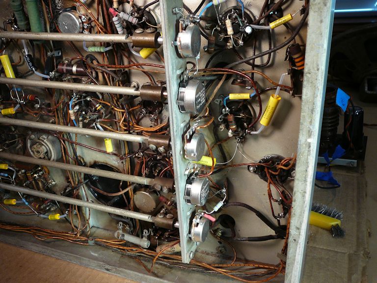


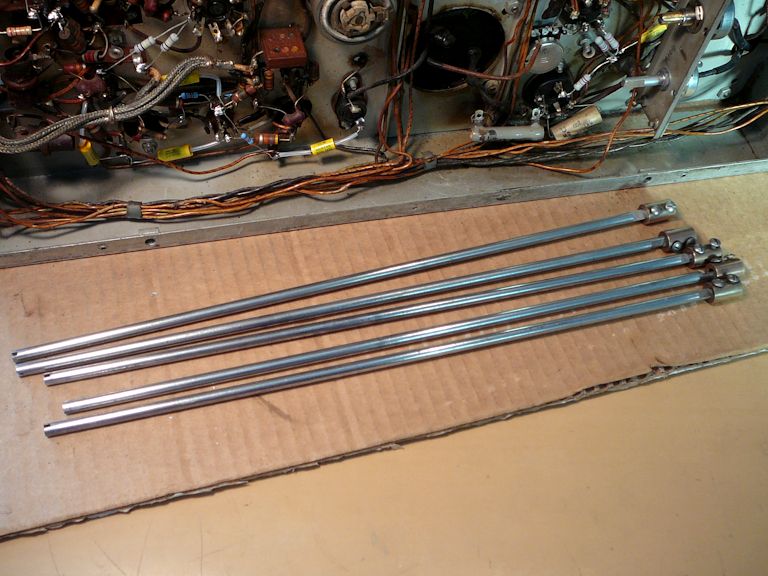
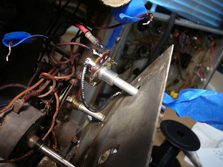
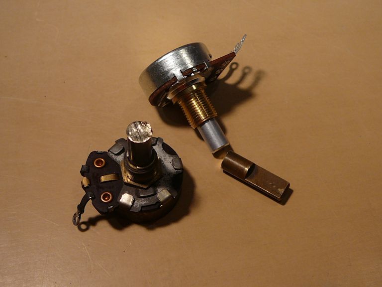
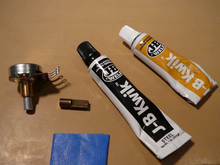
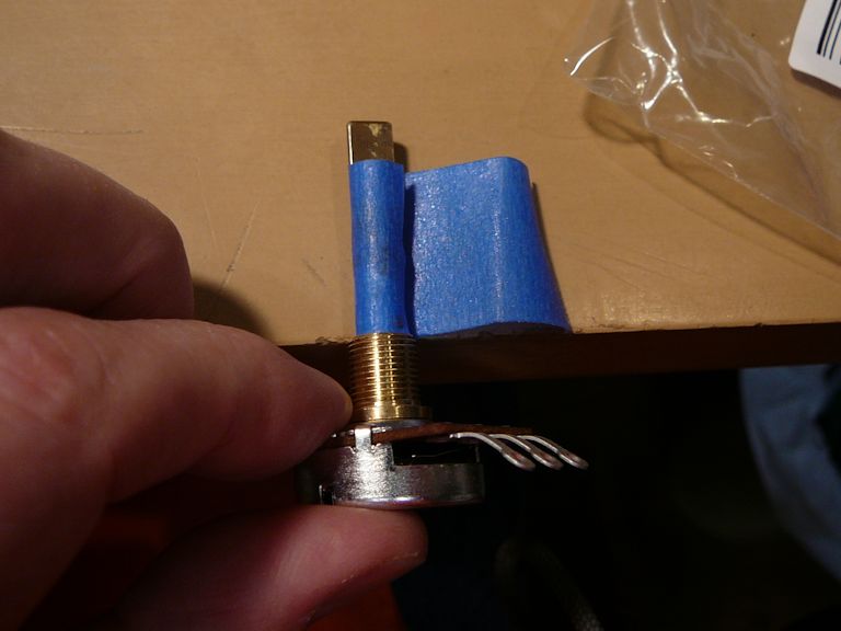
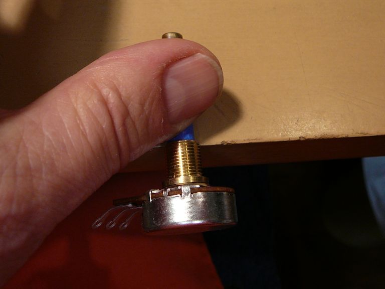
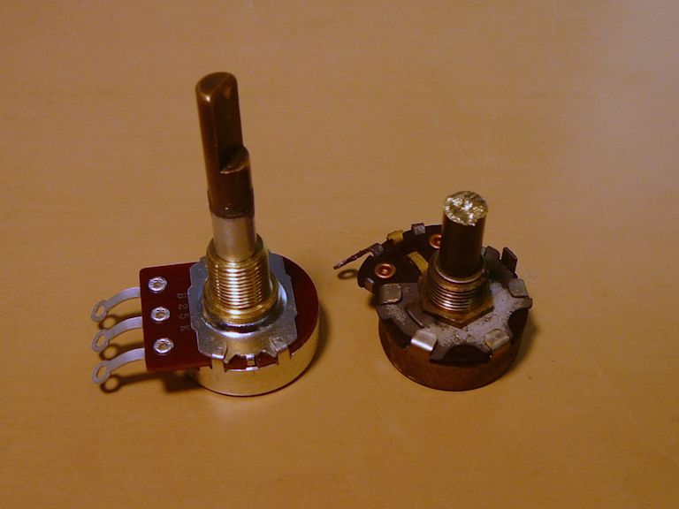
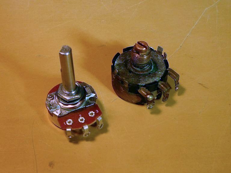
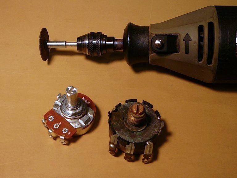
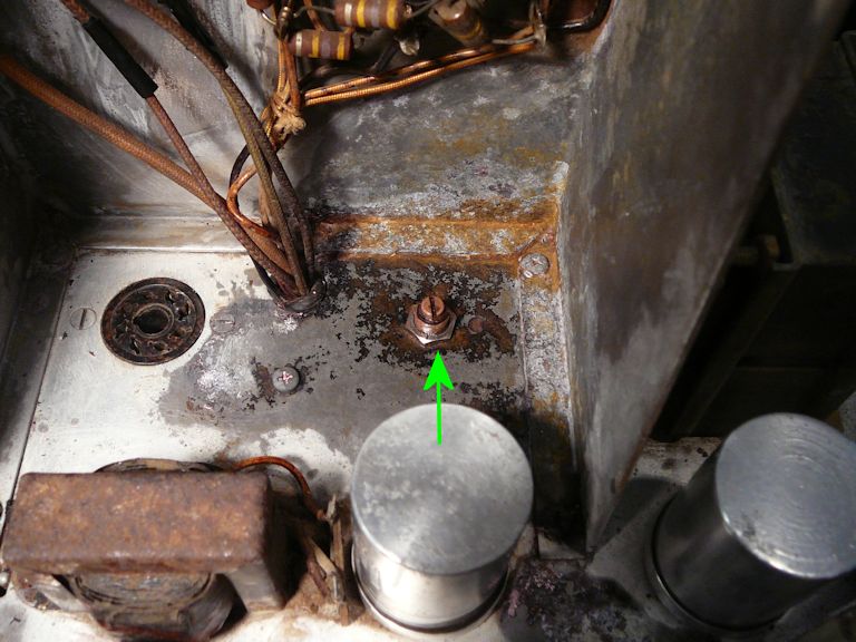

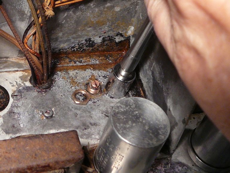
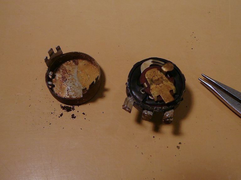
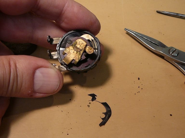
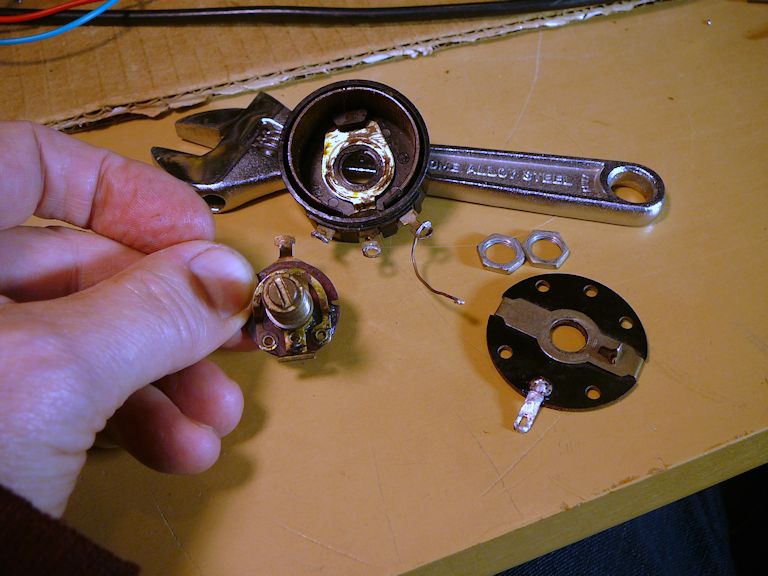
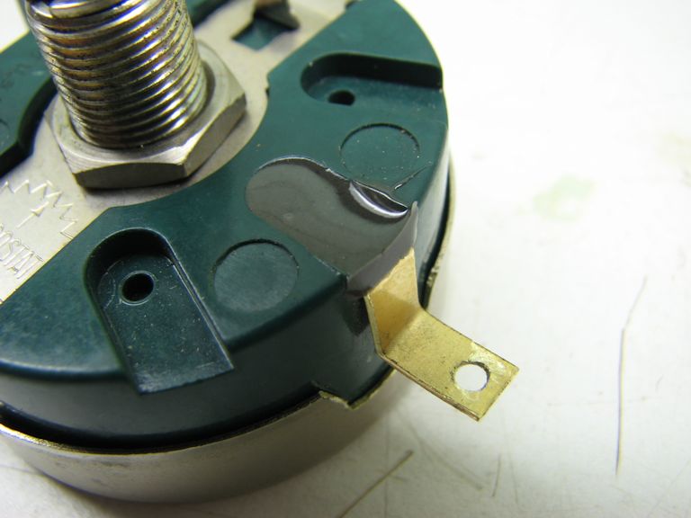
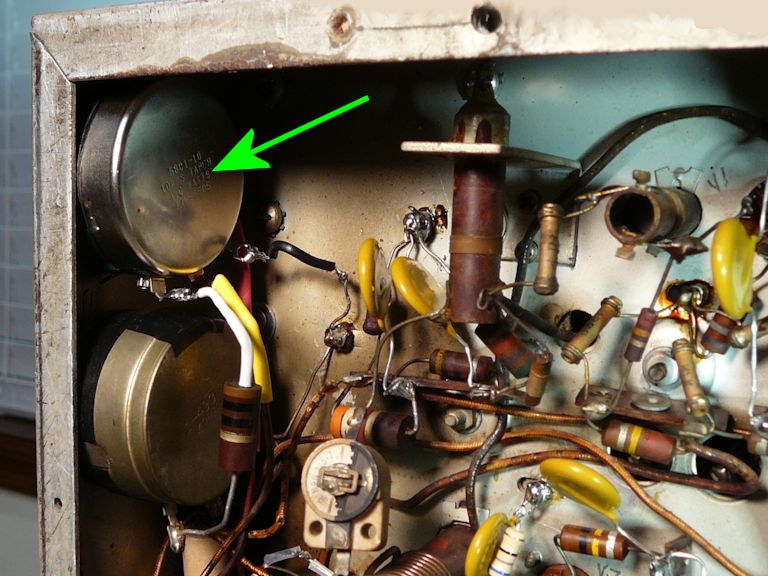


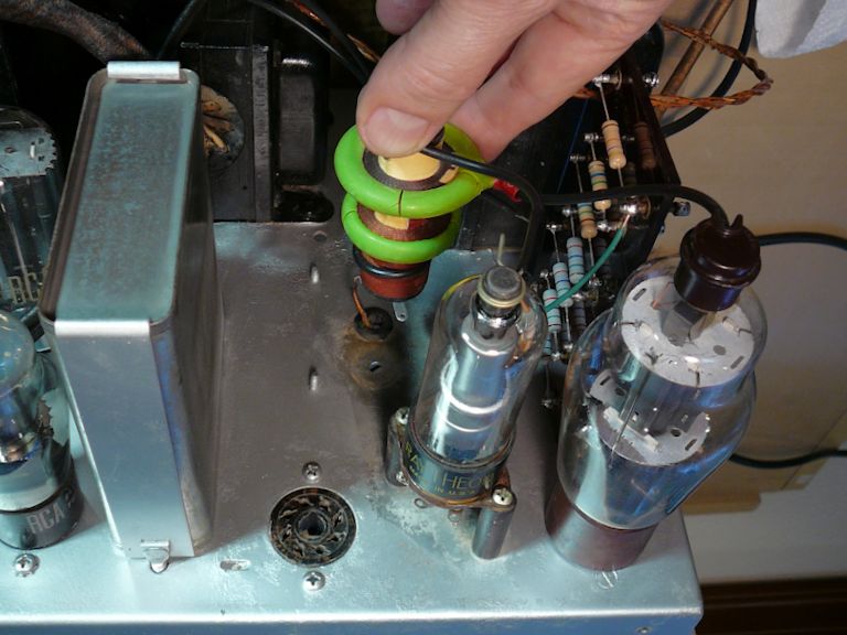

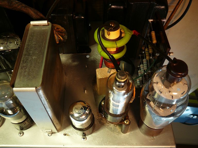
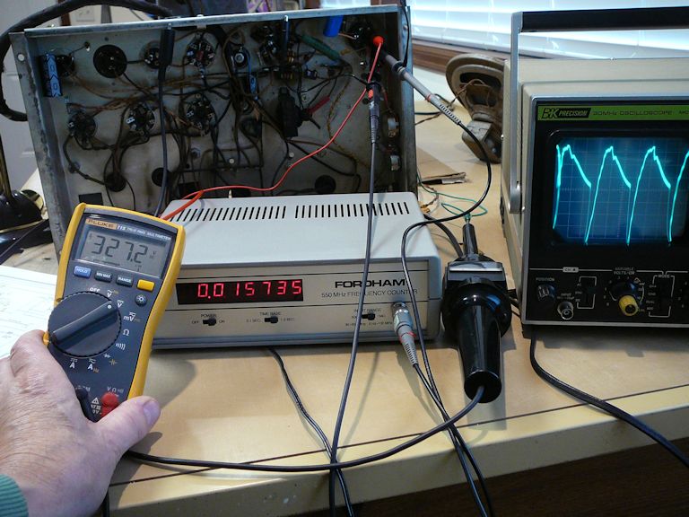
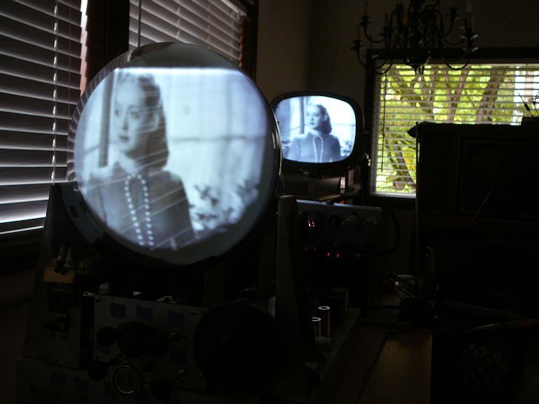
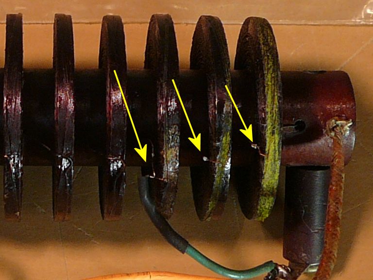
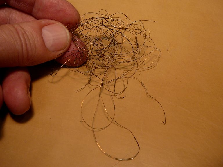
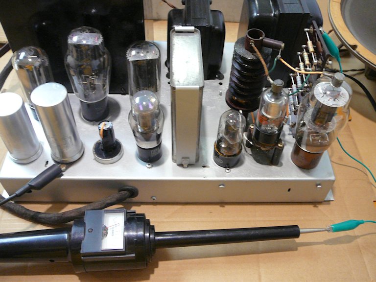
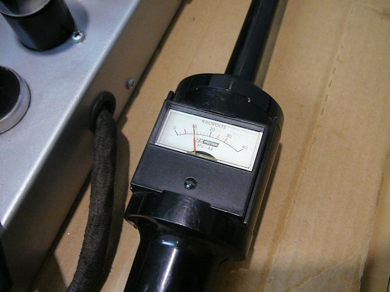
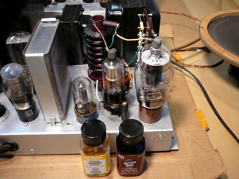
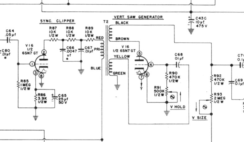
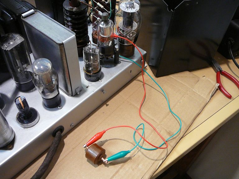
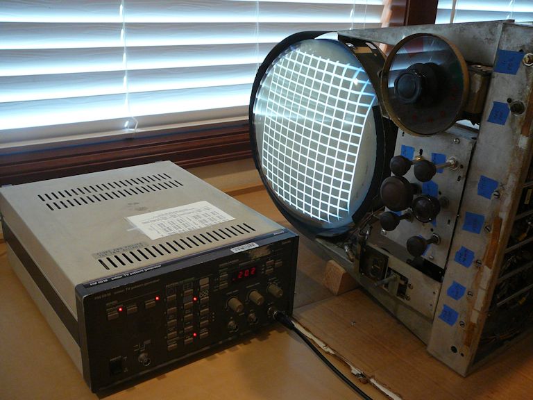
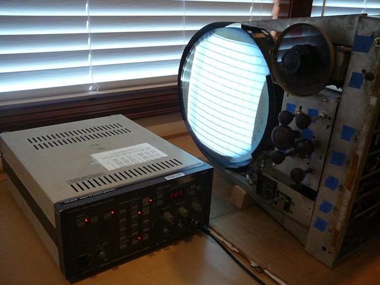
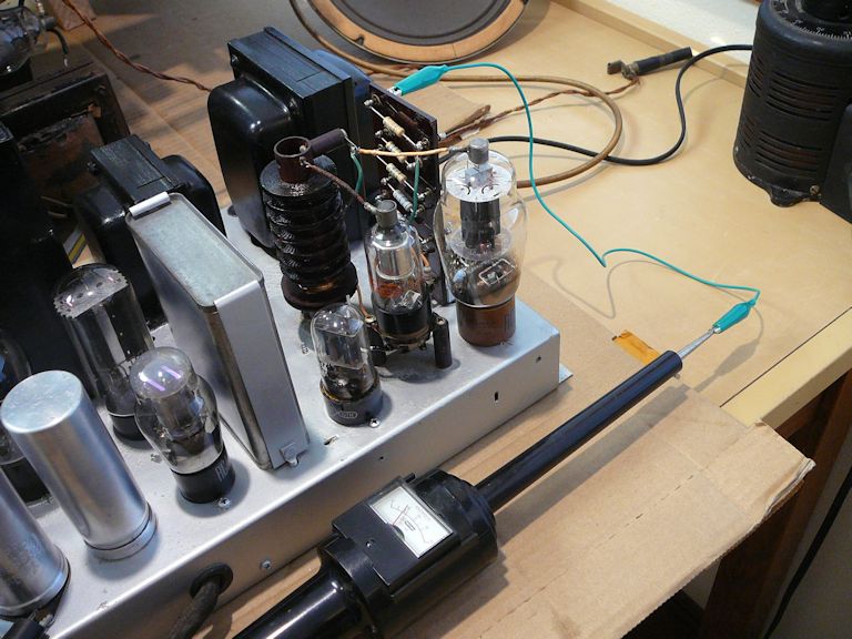
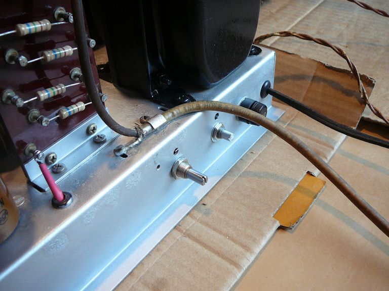
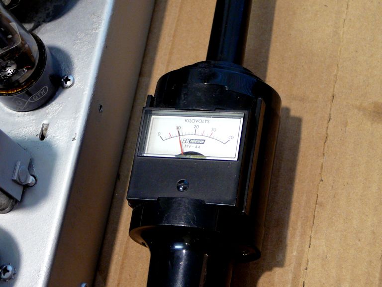
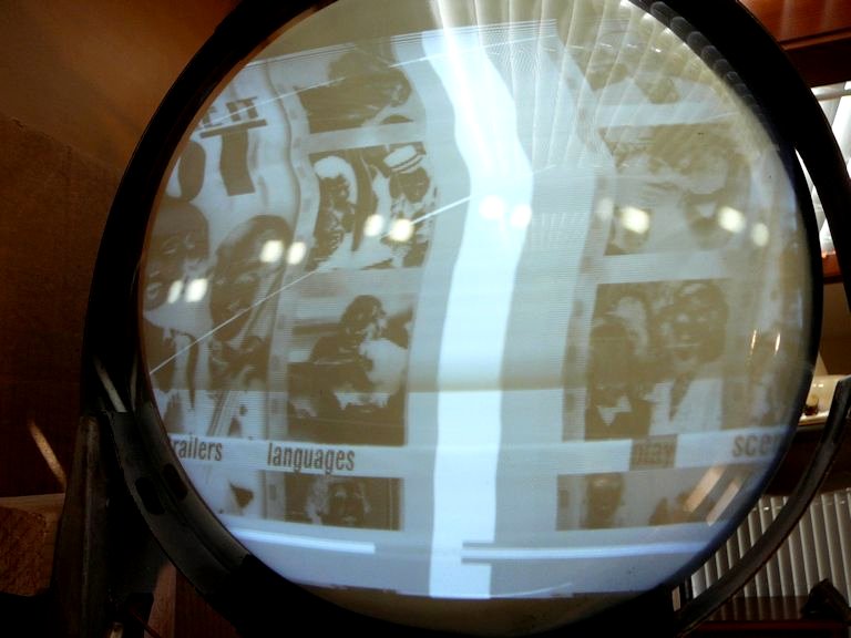
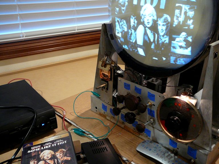
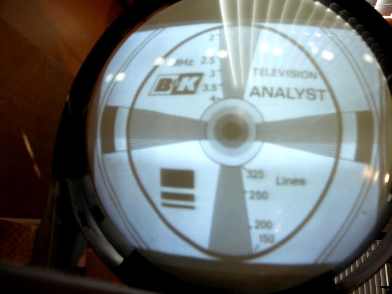
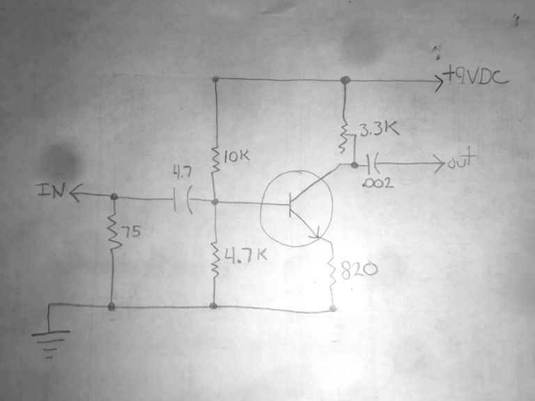
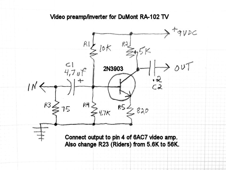
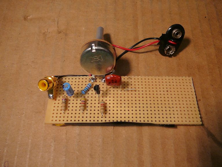
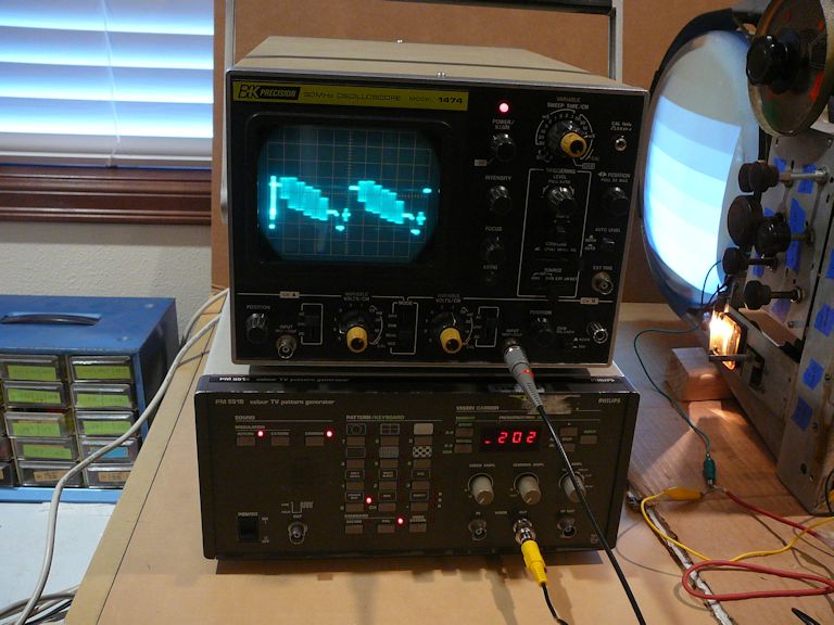
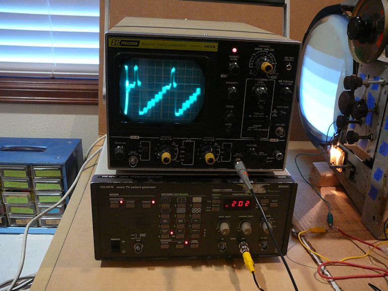
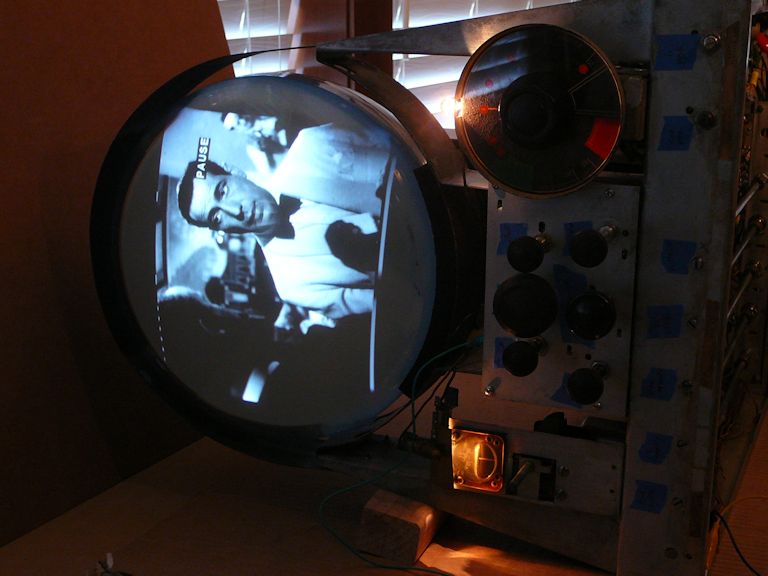
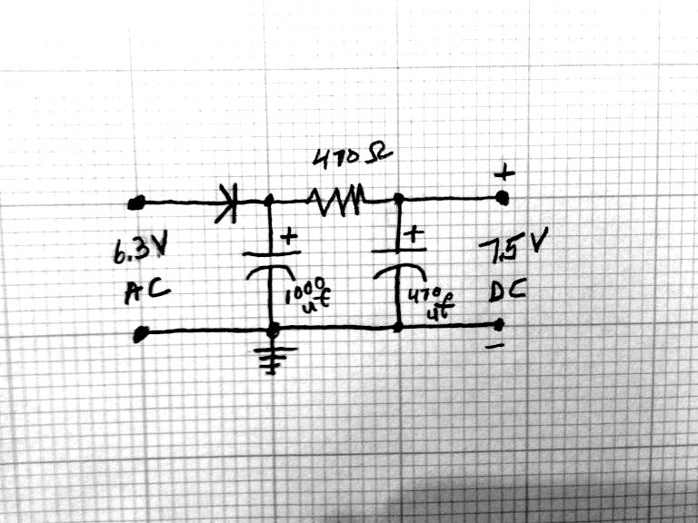

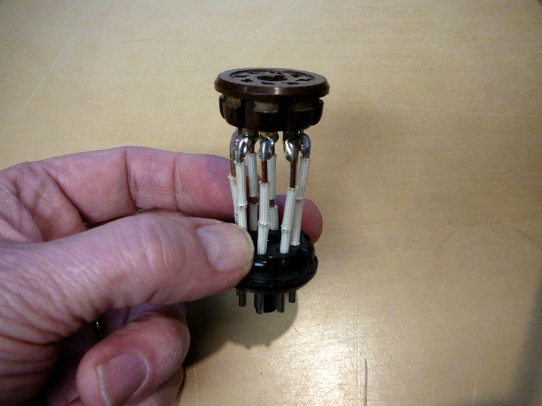
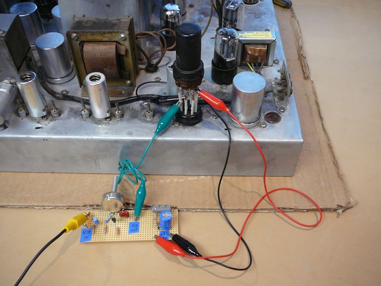
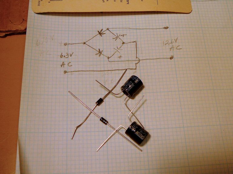
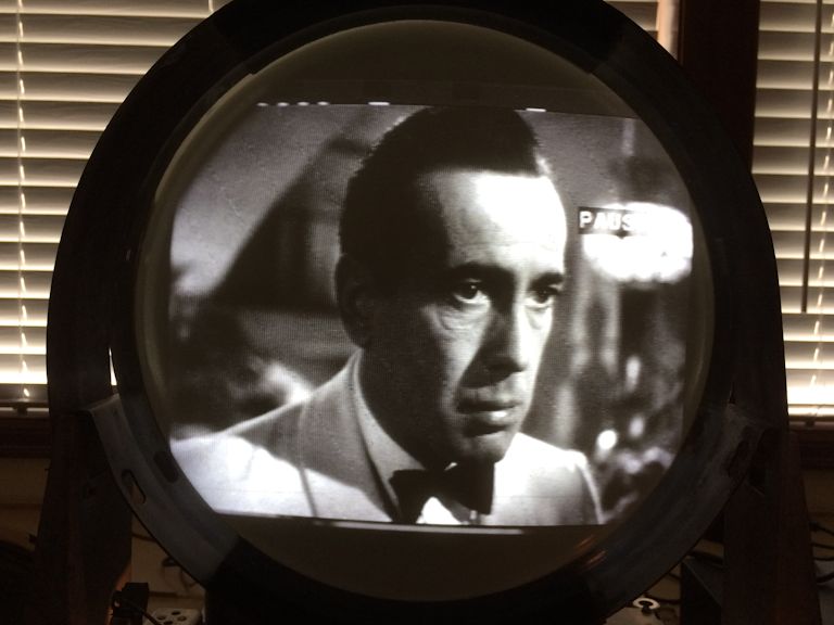
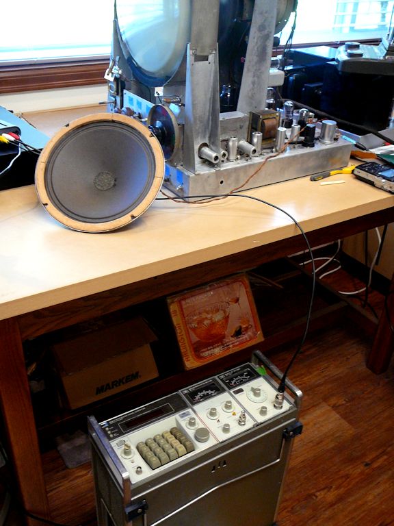
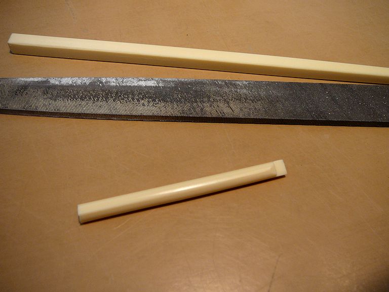
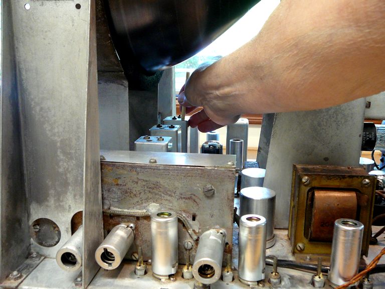
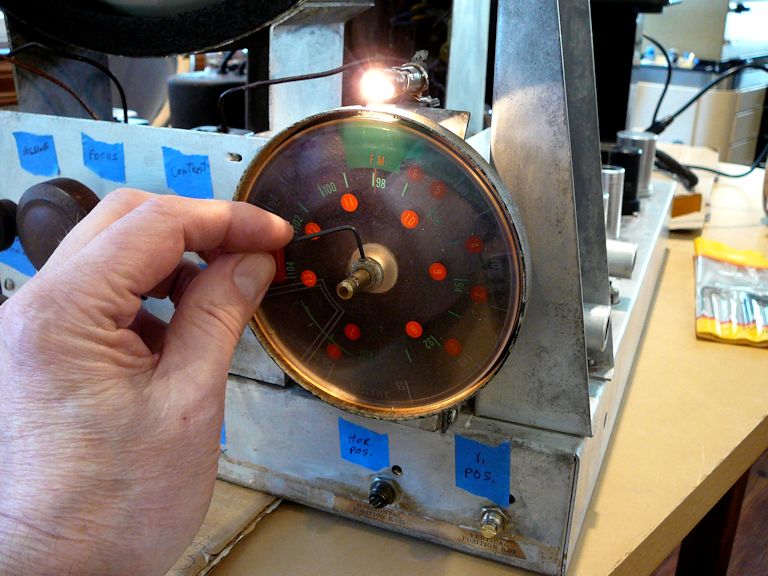
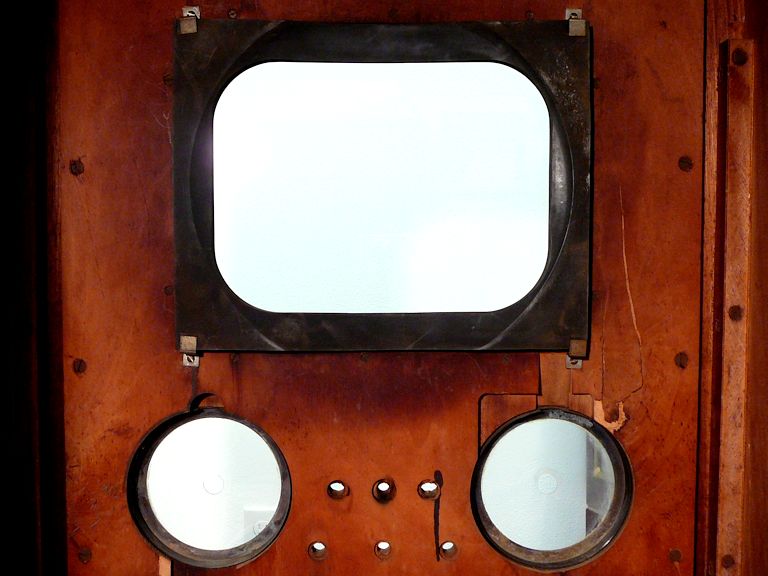
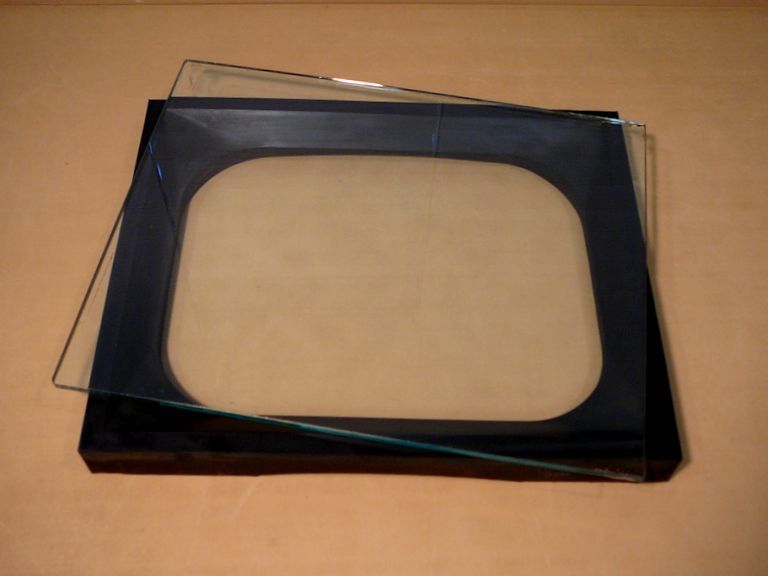
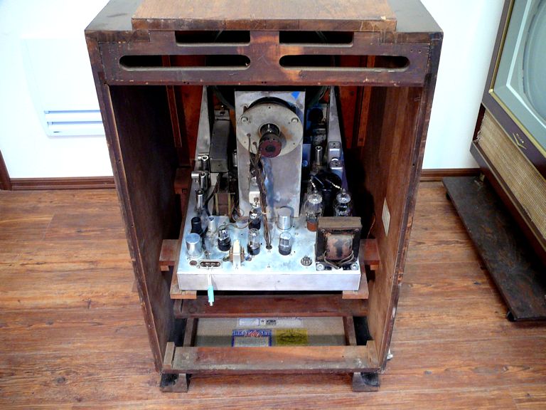
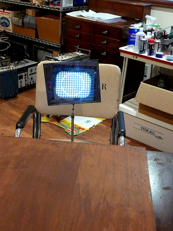
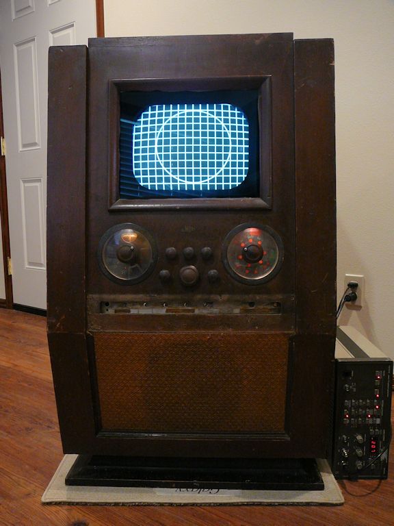
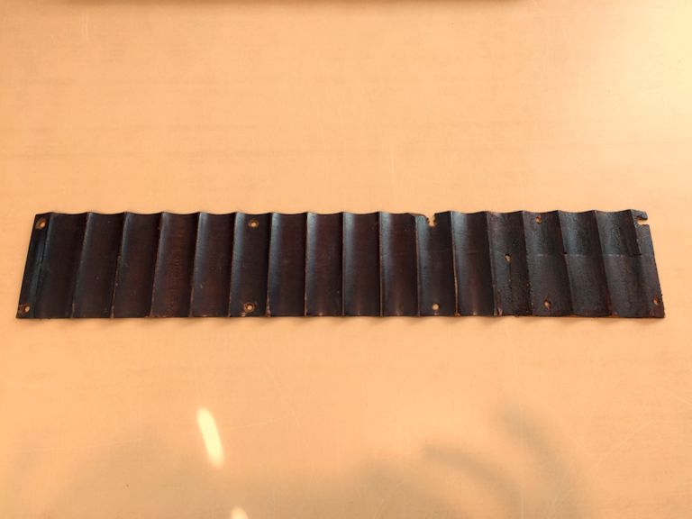
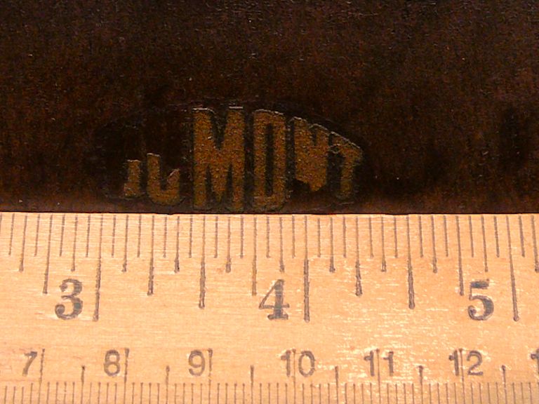
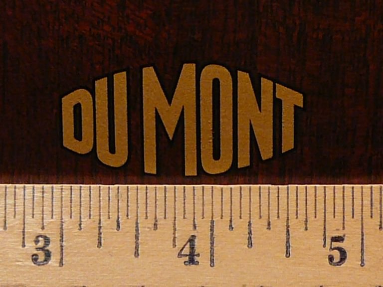
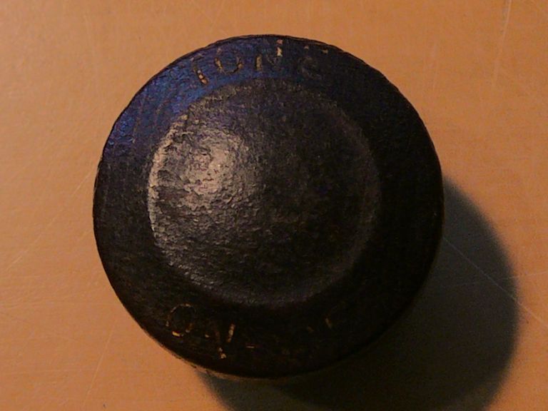
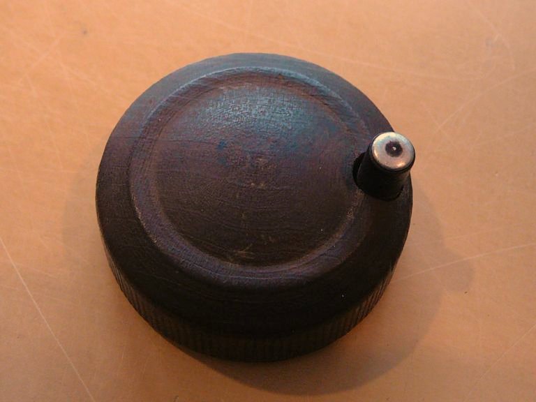
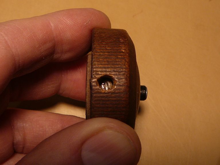
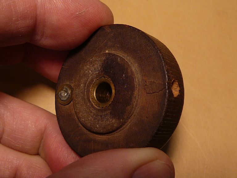
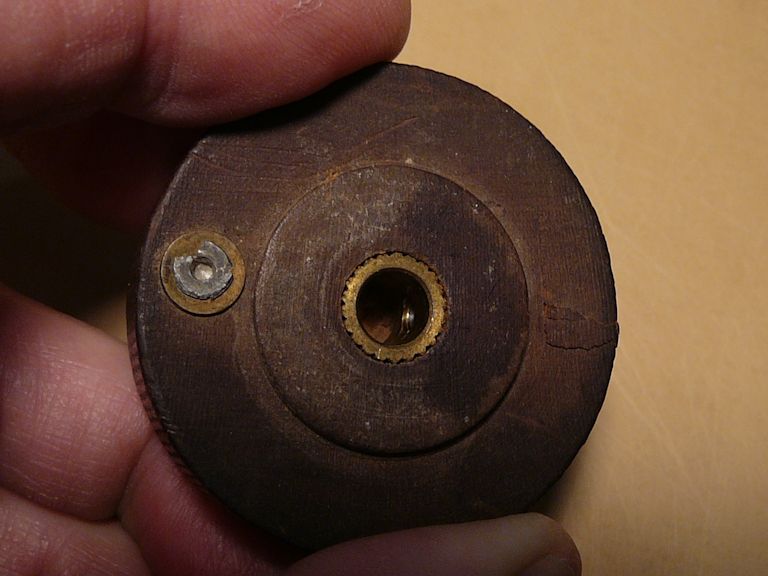
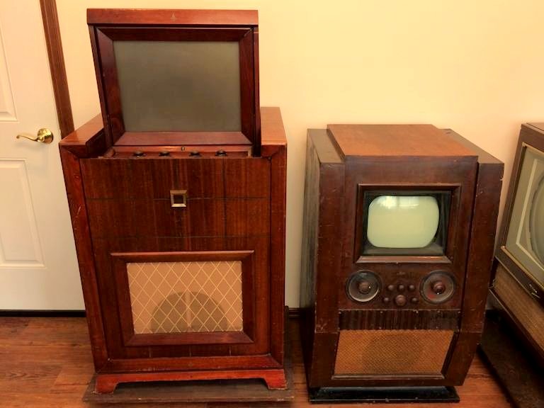
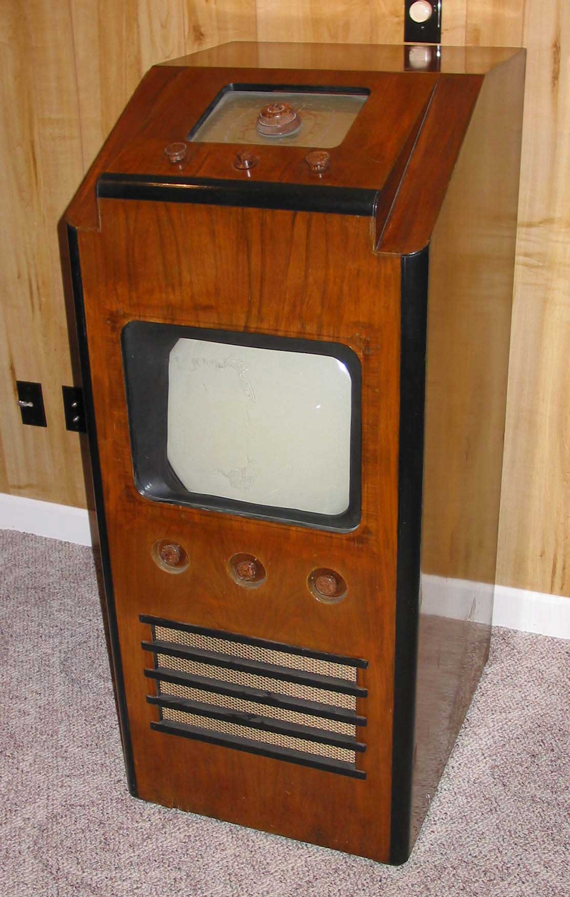
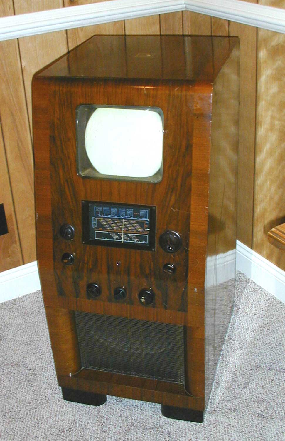
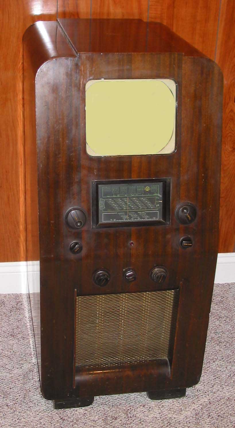
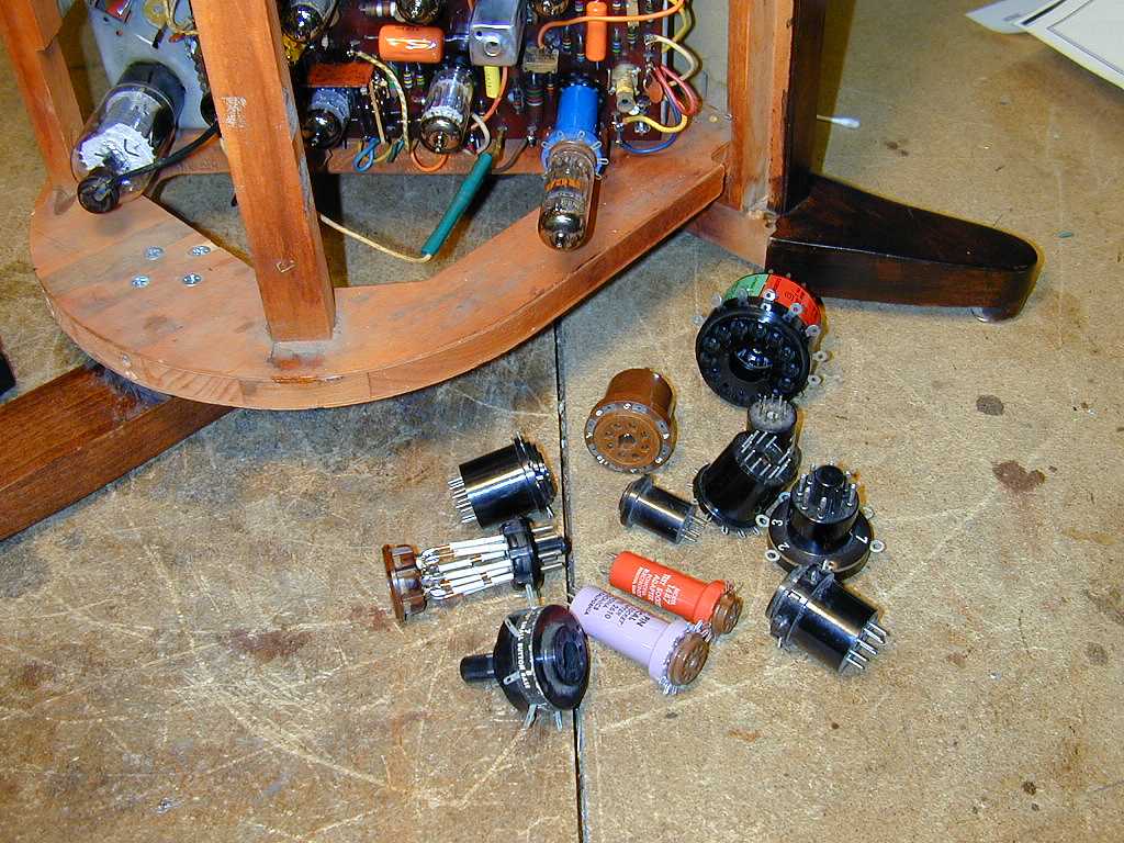