|

Direct Audio/Video Adapter for Vintage TVs


This article explains how I built an audio/video adapter for one of
my antique TVs, an Admiral 24C15.
With this little box, I can play movies or shows from a DVD player or similar source,
plugging into the TV with standard cables.
The adapter bypasses the TV's tuner, audio and IF (intermediate-frequency)
circuits and gives you the best sound and picture that your TV is capable of producing.
Its switch can also restore the connections to the TV's native circuits, so you
can toggle between a direct A/V source and the TV's antenna input whenever you choose.
Schematic and Parts List
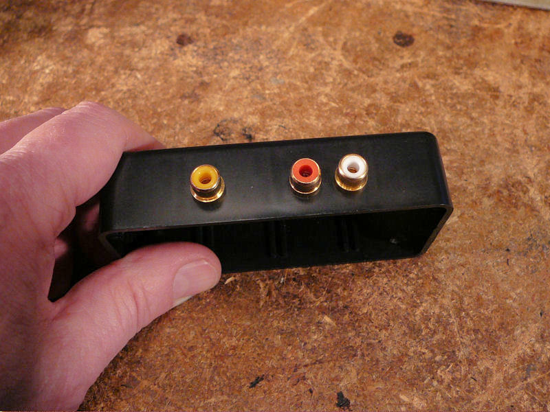
The A/V adapter can be built in a few hours and it uses readily
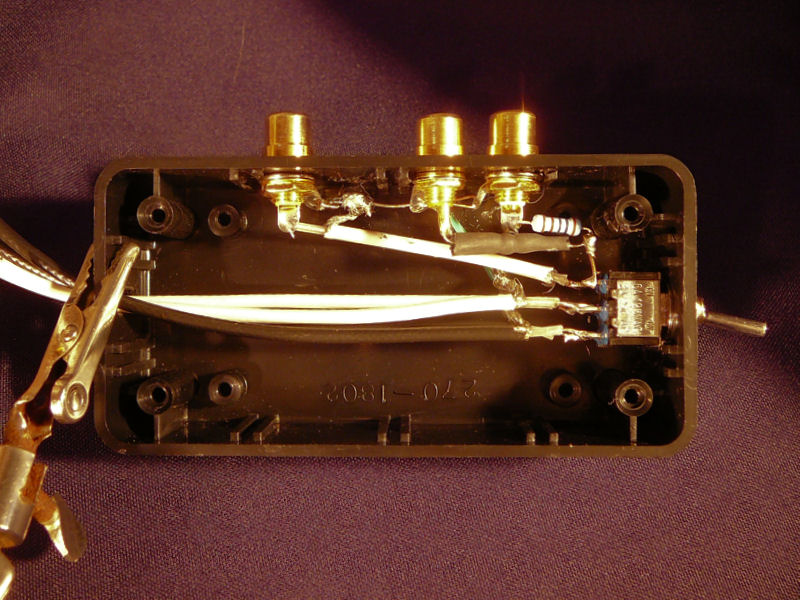
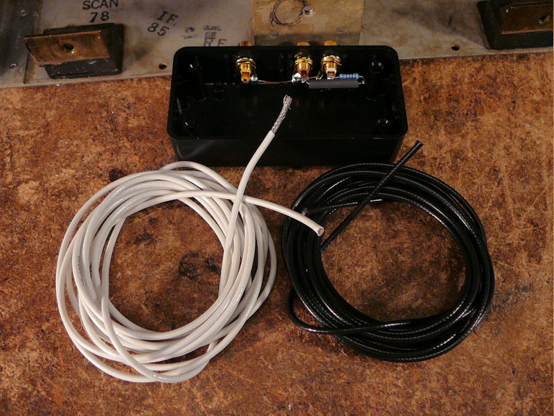
available parts. These photos show the finished adapter:
It's hard to imagine a simpler project. The adapter consists of three
phono jacks, two resistors and one switch inside a little box.
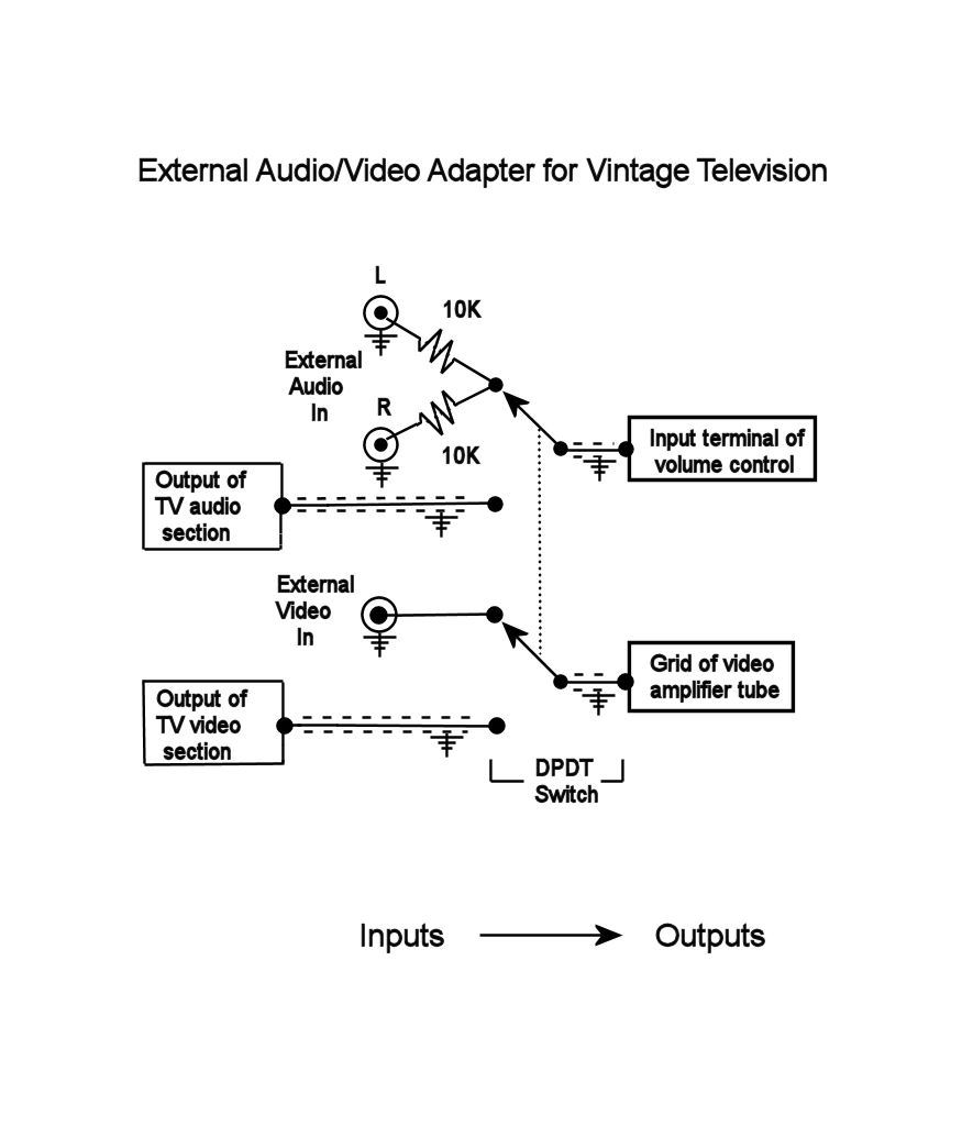
Here is the schematic:
When the switch is flipped up to the "External" position
as shown in the schematic, external audio and video sources are
routed to the TV's audio and video amplifier tubes. When the
switch is flipped down to the "Internal" position,
it disconnects the external sources and restores the native
connections between the TV's internal audio and video
sources and their amplifiers.
The schematic describes the adapter connection points in general
terms (for instance, "grid of video amplifier tube")
because the precise points may differ for other televisions.
Later in this article, I'll show where those points are located
in my set.
Here is the parts list:
For your convenience, I included links to Radio Shack part numbers for
most of these items. Note that Radio Shack may change part numbers or discontinue products at any time,
so if you don't find those exact parts, search their website (or another
supplier's site) for equivalents.
I used RG-174 cable because that was the most appropriate cable I could find at
my local surplus store. The type is not critical; any shielded cable
will do. I chose RG-174 because it's thin enough to fit through an
existing opening in my TV's chassis.
Building the Audio/Video Adapter
I housed my adapter in a little project box that's easy
to mount on the rear of the TV cabinet. If you don't mind drilling
four holes in the back of your chassis, you could mount the jacks
and switch on the rear chassis apron. I chose the box as a
less invasive option.
In the next photo, I have drilled holes in the box and installed
the three input jacks. My surplus store had jacks with yellow, red
and white cores to indicate video and audio.

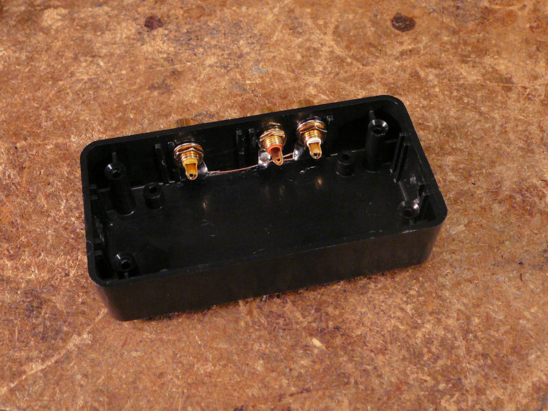
Next, I wired together the jacks' ground terminals:

I used shielded cable and ground connections to prevent hum in the
audio and hash in the video signal. When experimenting prior to building
the box, I had used unshielded clip leads to make temporary connections
in the chassis. Those seemed to produce normal picture and sound, but
I will be snaking these cables much closer to other leads and components,
so shielding and grounding is more important.
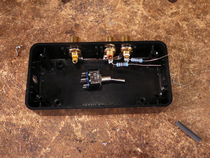
The following photo shows the DPDT (double-pole, double-throw) switch and
the two 10K resistors that sum together the stereo inputs into a monaural
audio signal. I'll use a short length of shrink wrap to insulate one
of the resistors in case that junction gets pushed around.

The switch will be installed at the right side of the box and the
cables will exit the box through a slot at the left.
I'll use this shielded, one-conductor cable to connect the switch to the
input/output points in the chassis:

The adapter shown here is actually the second one that I built.
The first version used shielded two-conductor cables—one cable for video and the
second for audio—because I happened to have a spool of that cable on hand.
The video looked reasonable, but when the adapter was switched
to my external source, I could faintly hear the audio from the antenna signal,
along with audio from the external source, caused by "crosstalk"
between the two audio cables contained inside the same shield.
After I replaced the two-conductor cables with pairs of one-conductor cables,
the interference between signals disappeared.
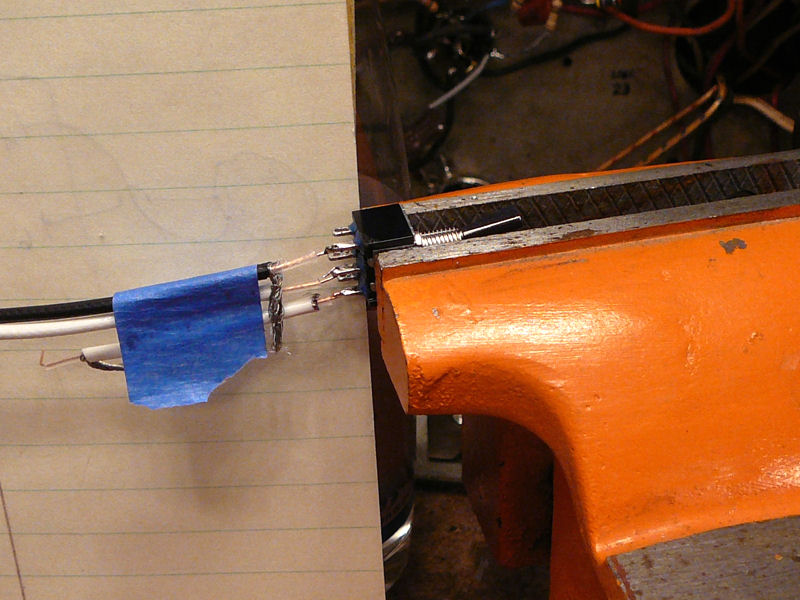
Here, I have begun to wire the switch:

Thin shielded cable is a little finicky to work with. I used a razor blade to
carefully slit the insulation and remove it. A stainless steel dental pick
worked well to tease apart the strands of shielding. After the shielding strands
had been unwoven, I rolled them back into a single wire which I then soldered
to the ground buss.
All of the internal connections have been made:
Choosing Internal Connection Points
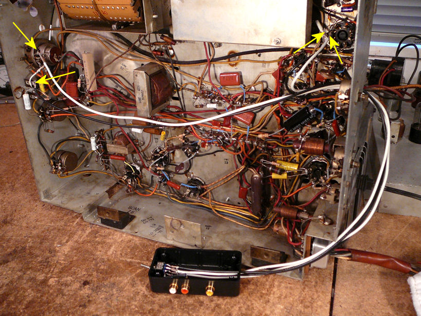
The next photo shows where I connected the four adapter cables under the
chassis of my Admiral 24C15. The cables are fed through a chassis opening that accommodates
the picture tube leads. In this view, the two audio cables are connected
at the two yellow arrows on the left, at the volume control, and the video cables at the arrows
on the right, at the video amplifier tube socket.
The black cables carry the internal signals from their sources to the adapter
and the white cables carry the signals—internal or external—from the adapter to the output tubes.
Now you can see why shielding is useful. When the adapter is switched to Internal, the audio
signal travels all the way from its origin near the volume control, out the chassis to the
adapter, through the switch, and all the way back to the volume control. Depending on where
I secure those cables when the project is finished, they may be near sources of
interference.
So, how did I choose these particular connection points?
The audio connection is easily understood. We want this adapter to substitute
an external audio signal for the TV's internal audio and retain the ability
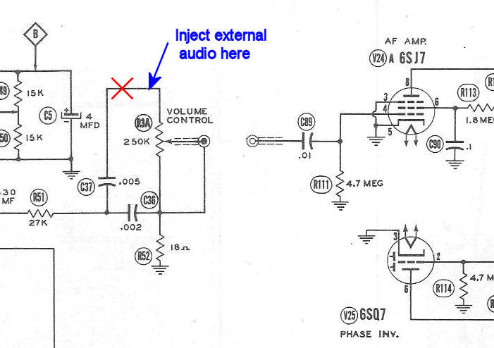
to make it louder or quieter using the volume control. The following snippet of
the Sams schematic shows the point that I chose. (You can download the complete 24C15
schematic from the ETF archive. It's a big
PDF file, so be patient while it downloads.)

In the previous diagram, the signal flow is from left to right. This TV has a separate
audio chassis connected to the main chassis through a shielded cable, as shown in
the schematic. If you follow the connection through the jacks, you see that the
signal goes to pin 4 of the audio amplifier tube, V24A. Whatever audio signal we
feed into pin 4 will be heard through the loudspeaker.
The red X shows where I cut the connection between capacitor C37 and the "hot"
end of the volume control potentiometer R3A. One cable is wired from C37 to
the audio side of the DPDT switch. The blue arrow shows where I wired the
incoming signal from the A/V adapter. The second cable from the audio side of
the switch connects to the indicated terminal of the volume control.
Our adapter simply switches that signal back or forth, choosing either
the TV's internal audio or the external audio from the adapter jacks.
When the adapter is switched to External, the internal
signal is disconnected and the external signal is fed to the
audio amp. When it's switched to Internal, the external
signal is disconnected and the internal signal is restored.
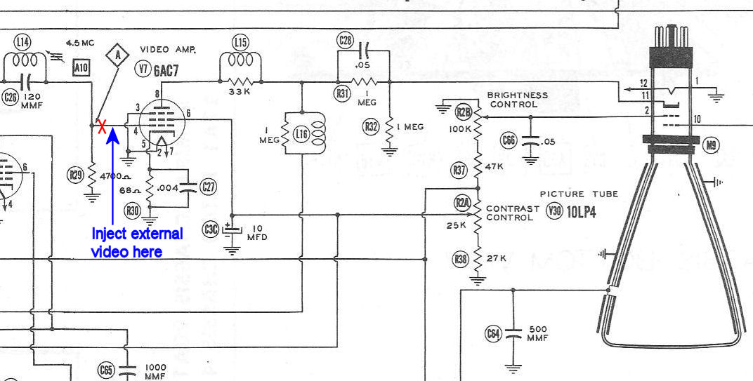
The next snippet shows where I connected the adapter's video cables,
at the grid (pin 4) of the video amplifier tube V7:
When the adapter is switched to External, it feeds the external video
to the amplifier tube. When switched to Internal, it restores the connection
to the TV's internal source.
Not All Designs Are Created Equal
If your TV's circuitry differs from this Admiral model, as many
will, you'll need to examine the schematic to determine the appropriate connection points.
The analog video signal in old TVs has a value of 1 volt peak-to-peak, with negative
sync. If the correct video connection point is not obvious from the schematic, you can
use an oscilloscope to search your video chain for that signal.
Caution: This Admiral TV has a transformer-type power supply. If
your television has a series-string (transformerless) power supply, then it's
possible—depending on which way the TV's unpolarized power plug is inserted—for
the TV chassis to be connected to the "hot" leg of the AC power line.
To avoid damaging your external device, you should operate the series-string
TV from an isolation transformer.
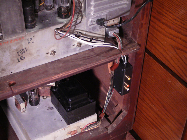
Using the Audio/Video Adapter
I installed the adapter box at a convenient spot in the rear of the TV cabinet:
Now, I can plug A/V cables from a DVD player or other source into the
adapter, and connect rabbit ears to the antenna input, selecting one
source or the other at the flick of a switch.
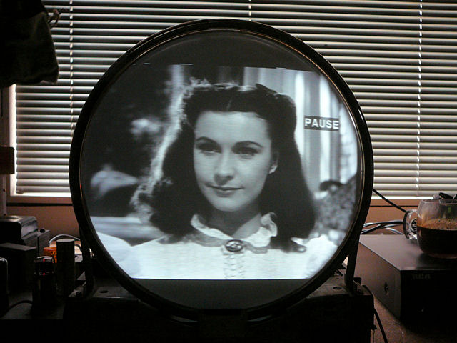
This brief video clip shows the box in operation, switching from
a DVD movie to an OTA signal received via antenna from my home transmitter.
My pocket camera takes lousy video, but at least you can
see that the adapter works.
So, was this project worth the effort? Let's look at some photos.
Time for a Pepsi Challenge!
At first glance, the direct video looks better, but not dramatically so.
The next two photos show the same DVD frame, comparing the TV's
antenna input (left photo) and the direct input from our adapter (right):


Zooming in makes the quality difference more apparent:


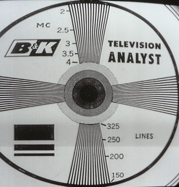
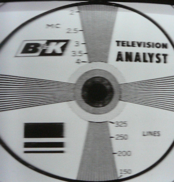
Displaying a test pattern erases all doubt and it allows us to quantify
the improvement. Again, the left photo shows the antenna input and
the right shows the direct input:

The vertical wedges in the center are important. They comprise two scales for measuring
the image quality: the bandwidth (top wedge) and the number of lines
of resolution (bottom wedge).
In this context, higher bandwidth is better. If you can distinguish separate lines
in the upper wedge all the way to about 3 mc (3 MHz), your TV is in decent shape. A lower
bandwidth reading means that some bandwidth is being lost when the TV processes
the signal through its tuner and IF sections. Your TV might benefit from
a full realignment (or, it may simply be a cheap design with a lousy IF section).
In the direct video example, the bandwidth lines are clearly distinguishable all
the way to 4 MHz. This translates into a very sharp picture, so sharp
that I needed to back off on the Focus control to avoid an unnatural, too-crisp
picture. The bandwidth is much lower in the antenna example: the vertical
lines disappear just beyond 2 MHz.
It's not that this TV's antenna
input looks awful at a normal viewing distance—it's actually quite good,
as shown by the following picture taken during restoration—merely
that the direct video input looks better.

This Admiral model is pretty well designed, but its alignment may have drifted
a bit during the last 60-odd years, due to component aging. Design limitations also
play a role here. The IF strip in an inexpensive TV may pass less bandwidth than
the ideal, no matter how perfectly it is restored and realigned.
I can't quantify the audio improvement, but comparing signals for only a
few seconds would convince anyone that direct injection sounds
much better. The audio is strong and pure, with none of the annoying buzz
that many vintage TVs produce when displaying high-contrast scenes such as
black lettering on a white background.
Pros and Cons of Direct A/V Input
Vintage TVs were designed to receive over-the-air signals
through an antenna. When I restore a set, my goal is to make it
work as designed. I also use a home transmitter
to broadcast programming throughout the house, so that a
TV in any room can receive the program using a rabbit ear antenna.
I like using my TVs "the old fashioned way," and I also like
to restore the whole television from front to back.
In a sense, direct input feels like cheating, since you're bypassing
roughly one-third of the TV's circuitry, using it as a monitor
rather than a receiver.
On the other hand, sometimes I just want to play a DVD and
enjoy the best picture and sound. With direct input,
the results can be spectacular. No more furry pictures or buzzy sound.
The image is crisp and rich, the sound is crystal clear.
A switchable adapter gives you the best of both
worlds, versus hardwired direct connections.
I can use the antenna input whenever I like, and the adapter
could be removed with minimal effort, if I decided
to return the TV to original condition.
People normally watch programs, not test patterns,
and every vintage TV is a little different. If you're wondering whether
it's worth the bother to add an A/V adapter to your set,
you can experiment with clip leads, as I did before building
this adapter. (I recommend that experiment in any case, to make
sure you have chosen the right connection points.)
Why Not Simply Align the TV?
As noted earlier, every TV's output quality depends on properly
aligned tuner, IF, and audio circuits. In practice, you'll find that most
vintage TVs don't need a full realignment unless some ignorant person has
messed with the alignment. However, some sets—including
this one, perhaps—might benefit from a touch-up.
Of all TV restoration techniques, alignment of the tuner and IF probably requires the
highest skill level, as well as specialized equipment such as a sweep generator
and marker/adder. I don't own such equipment and I don't have that skill, at least
not yet.
Furthermore, every design has limits, so alignment can't produce better output
than a TV's circuits can support.
I'm very familiar with audio alignment,
and there's a limit to the audio quality that you'll get from any
split-sound system like the Admiral's.
The audio from direct input is noticeably better in this TV, even though I
aligned (and realigned) the audio section during restoration.
I suspect that aligning the IF strip would improve its video quality,
but perhaps not quite to the level produced by direct input.
Plug 'n Play Construction
One further refinement is suggested by a 1956 article
from RCA Broadcast News, describing a video adapter for the
RCA CT-100 color set. Rather than
cut the video connection under the chassis, the author built an
above-chassis adapter using a tube socket and base.
To use that adapter, you insert its base into the socket of
the video amplifier tube, and plug the tube into the
adapter socket. (That adapter also included a video preamplifier,
but we can ignore the preamplifier in this discussion,
since a standard-level video input is sufficient to drive the Admiral's
video amp.)
To build a plug 'n play A/V adapter for my Admiral TV, you could
use a similar socket-and-base pair for each of the amplifiers.
The cable connections from the box would be routed to the
adapter sockets rather than hardwired under the chassis. To
return the TV to stock condition, you would simply unplug the adapter
sockets and return the tubes to their native sockets.
Speaking of the CT-100, immediately after finishing this adapter, I
updated the one I had built for that set a couple of years ago. You
can read all about that in the article
Video Adapter for RCA CT-100 Television.
This electronic construction project, including all descriptions, diagrams, photos, and the underlying electronic design, is published here for the noncommercial use of radio hobbyists. You may print and reproduce these project instructions for your personal use. Commercial use of this material is not authorized.
|