GE S-22X Tombstone Radio with Clock (1934)


This stately GE S-22X tombstone radio, with its rare speaker-mounted clock, holds
the record for longest-delayed project in this house. I began restoring it in 1998 and
finished it in 2013 . . . fifteen years later!
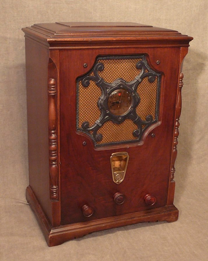
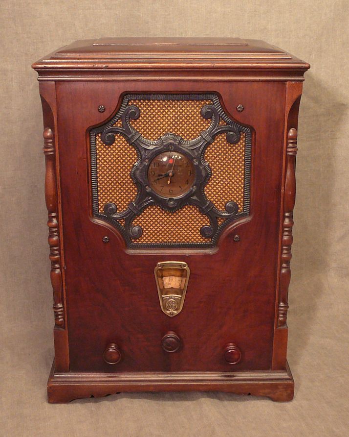
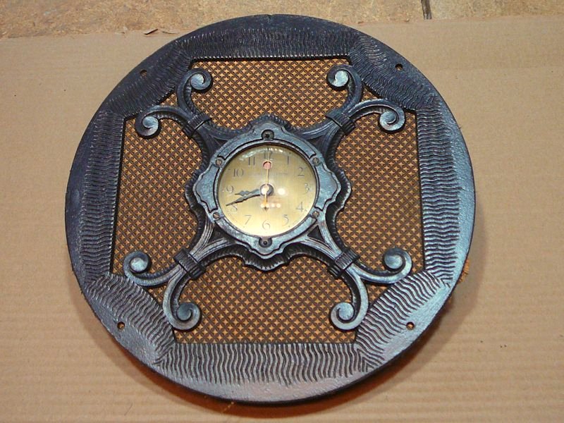
Here are a couple of photos of the restored radio:
Description
The General Electric S-22X was manufactured in 1934. The X in the model number indicates the clock.
Unlike modern clock radios, this clock doesn't turn the radio on and off; it merely keeps time.
A little circle in the dial face turns red when the clock has lost power, a signal that you
need to reset the time.
GE made about half a dozen S-22 models during the years 1931-1934, including a console set and
a tombstone with a removable stand; it was common for manufacturers
to offer the same chassis in a variety of cabinet styles. The plain
tombstone model S-22 has no clock and its grille cloth has a large floral pattern.
The S-22 has eight tubes:
| Tube |
Type |
Function |
| V1 |
24A |
RF amplifier |
| V2 |
27 |
Oscillator |
| V3 |
35 |
First detector |
| V4 |
35 |
IF amplifier |
| V5 |
27 |
Second detector |
| V6 |
45 |
Audio power amplifier |
| V7 |
45 |
Audio power amplifier |
| V8 |
80 |
Power rectifier |
With a radio-frequency (RF) amplifier at the beginning of its signal
path, this was a sensitive radio for its time. The oscillator and
intermediate-frequency (IF) tubes make it a superheterodyne
receiver, of course. The two 45 audio tubes and stout eight-inch
speaker provide above-average audio with plenty of volume.
The S-22X does not have automatic gain control (AGC). As with my early
Philco Model 90, you need to manually adjust the volume when
you tune between stations with faint and strong signals.
The schematic
for this radio is listed under RCA Model R-7 in Riders.
Perhaps GE licensed the design from RCA; many radio and TV companies
licensed patents and even complete designs from RCA over the decades.
Compared to newer radios, the parts in this one are pretty hefty. Some
look more like auto parts than electronic parts!
When new, this radio doubtless served as the family's primary
"entertainment center." People were only too happy to own a large,
handsome-looking radio in those days. It wasn't until World War II,
which brought technological advances in miniaturization, and the 1950s,
when television took center stage, that space-saving became a big
factor in radio design.
The chassis construction is a bit peculiar by later standards.
Several of the small capacitors were enclosed in a "capacitor pack:"
a metal can filled with tar. Several resistors were mounted on an
insulated phenolic board. Perhaps this was an early attempt at modular design,
the idea being that a repairman could just replace an entire module if any
of its components failed.
Sixty-odd years later, of course, replacement packs are unavailable and you
wouldn't want to use one even if you found it, since the capacitors inside would
have degraded with age.
Installing new capacitors is not rocket science. I have done it for dozens of
radios and TVs and you can read all about the process in my article,
Replacing Capacitors in Old Radios and TVs.
However, it's a messy, tedious job to melt the old tar out of a potted
can and replace the innards.
Soon after buying the radio, I repaired and refinished its wooden cabinet,
but the electronic restoration didn't seem like fun, so I put the radio
into a box where it languished for years.
Finding a GE S-22X
This radio was another garage sale find. My wife phoned me one day to say
that she had seen a "funny old clock radio" at a sale.
I was heading in that direction anyway, so I decided to stop by,
even though I assumed it was yet another plastic 1950s clock radio,
of which I already had too many.
When I spotted this set, my ears immediately pricked up. It's unusual to see a clock
in any 1930s radio.
The radio looked a little rough. Two of its eight tubes were missing, and a
quick peek at the label confirmed that they are the scarce, expensive type 45s.
I mentioned this to the owner, remarking that the
previous owner may not have been clever enough to fix it, but at least
had enough brains to take the two most valuable tubes.
I also pointed out the torn grille cloth, the missing knobs, and
the holes in the top of the cabinet where a handle had once been mounted.
After a little more tap-dancing over the price, I handed over a couple
of twenties and loaded it up.
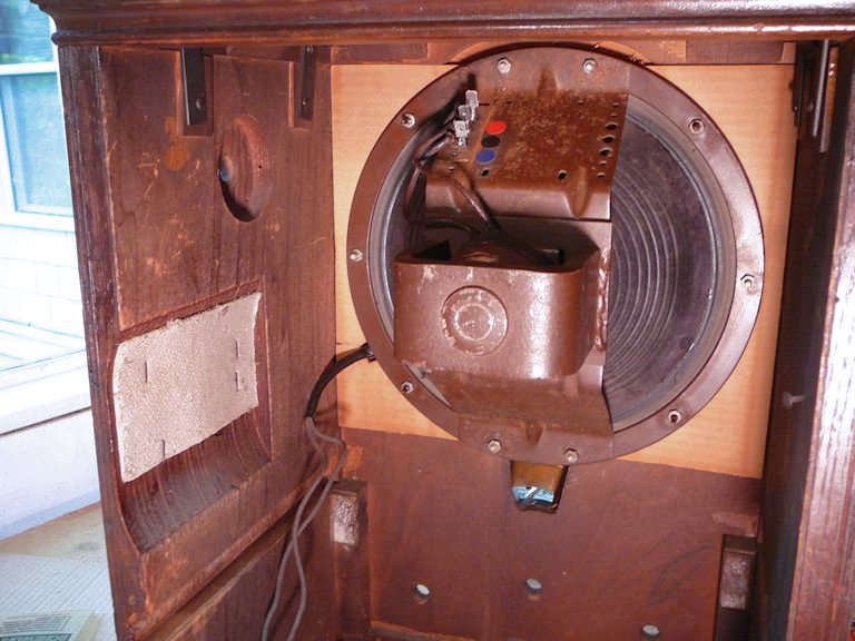
Getting Started
The following picture shows the cabinet as found. The clock is mounted in the
center of the speaker grille, supported by a decorative cast metal frame.

As you can see, the grille cloth has a big tear, although surprisingly,
the speaker cone behind it was not damaged.
As soon as I got the radio home, I inspected it more closely.
Everything seemed to be in place and the six remaining
tubes all tested fine. I set the radio aside and powered up my computer
in search of a pair of 45 tubes. Within a few minutes, I had ordered
a couple of fresh ones, along with the schematic. (When this project began,
free online schematics were not available, as they are today.)
Two days later, while pawing through a box of stuff, I discovered
four 45 tubes new in their original boxes, mixed in with a number of others
I had photographed for my Tube Gallery. Oops!
Since I had already sent payment for the two additional 45s, I chalked that
boo-boo up to faulty memory. No doubt I'll find a use for all of
them someday.
With fresh 45 tubes in hand, I could check out
the set. After cleaning all the tube sockets and pins
(see First Steps In Restoration),
I installed the 45s and powered up the radio
under slowly increasing voltage. Doing this with a variac and ammeter lets you
watch for problems such as short circuits.
Wonder of wonders, it worked! The tuner was
frozen on its moorings, but after the power approached about 95 volts,
I could definitely hear the right kinds of noises: background static
and a faint station, without any hum. Encouraged by these signs of life,
I powered it down and removed the chassis from its cabinet, to
begin cleanup and restoration.
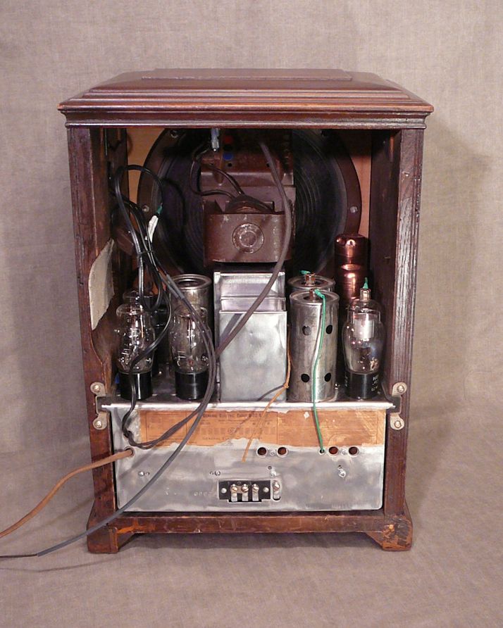
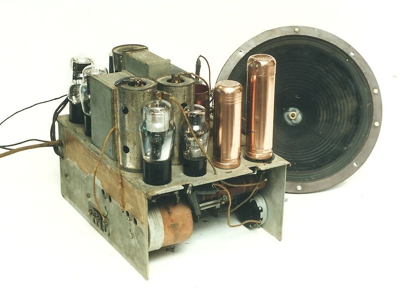
The following view of the unrestored chassis shows a couple of
unusual features. Like many tube sets, this one has a pair of
tall electrolytic capacitors in metal cans; these serve as filters
for the power supply. In modern radios, the capacitor cans are
aluminum, or sometimes cardboard, but these are solid copper!
By the time this photo was taken, I had polished them to
a nice glow.

The copper electrolytic cans have little vent holes on the
top, making them resemble old pepper shakers.
A "wet" electrolytic consists of a flat metal
coil immersed in a mild solution of boric acid. In many cases, the solution
leaks out, rendering the unit inoperative.
I didn't expect either capacitor to work, but when I checked them,
one tested at the specified value and the other was weak but usable. Incredible! You can read
more about this type of capacitor, and see what's
inside one, in my Philco Model 60 Cathedral
restoration article.
The previous photo also shows one of the large, copper-colored cans
underneath the chassis. At first, I wasn't
sure what these big cans were. When the schematic arrived a few days later,
I discovered that they hold intermediate frequency (IF) transformers;
in newer radios, those are usually housed in small rectangular aluminum cans.
The drive mechanism for the tuner dial is a little different.
The dial is a shallow cone of cardboard with printed markings,
riveted onto a circular metal wheel that has teeth notched
around its inner perimeter. The shaft of the tuning knob goes
inside the toothed wheel and it has a round rubber washer to grip the teeth
and drive the wheel.
My Stewart-Warner 102-A tombstone
uses a similar tuning mechanism. These rubber-driven tuners work well
until the rubber dries out and becomes eroded by the teeth, losing its grip
on the wheel.
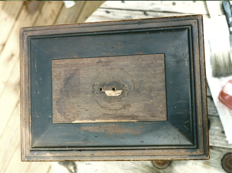
Replacing Cabinet Veneer
The only serious damage to the cabinet was on top where the handle had been mounted, shown in this view:

The veneer under the handle was chipped and it had circular
gouges, caused when the handle was loose. I'll replace the whole piece.
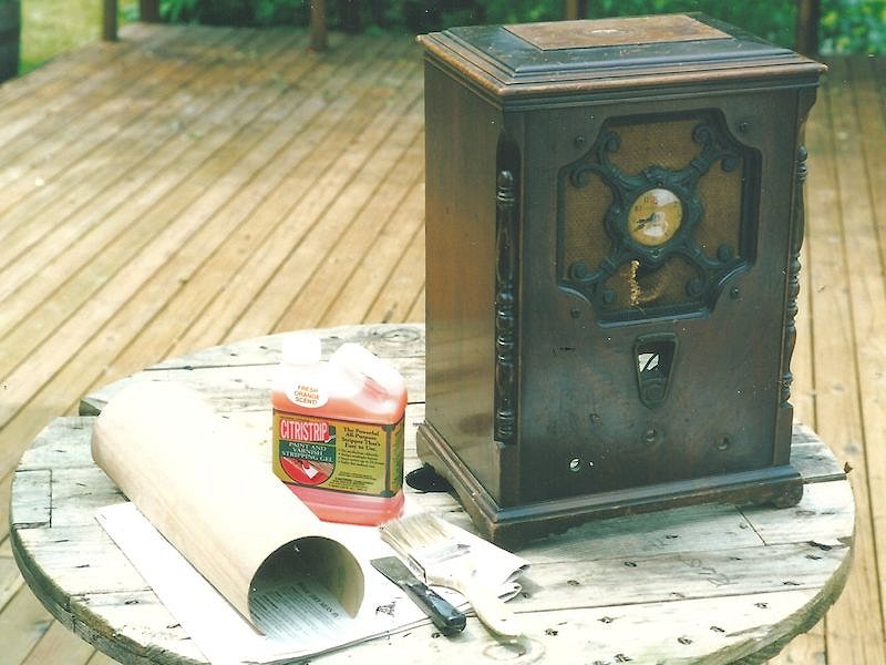
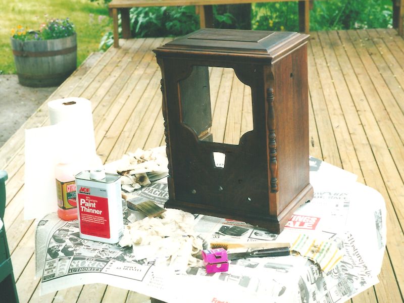
Since some finish in the surrounding area had flaked off completely, I decided
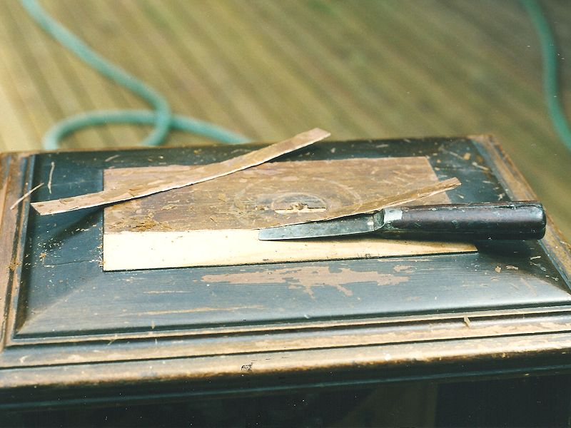
to strip and recolor the entire top. The next photo shows the cabinet
with the materials I'll need for this step: a new piece of veneer,
a jug of Citri-Strip paint stripper, and a small putty knife.
My local lumberyard sells veneer in 4 x 8 foot sheets, a lot more than
I need for this job, so I convinced a local furniture restorer
to sell me a scrap piece for a couple of bucks. In case of mishaps, I got a piece
more than twice as large as I thought I'd need.
The next photo shows how I removed the old veneer, slipping the putty knife
under a loose edge and taking it off in strips. This took less than a minute.

After the veneer was gone, I cleaned the bare
underlying wood with paint thinner to prepare it for gluing.
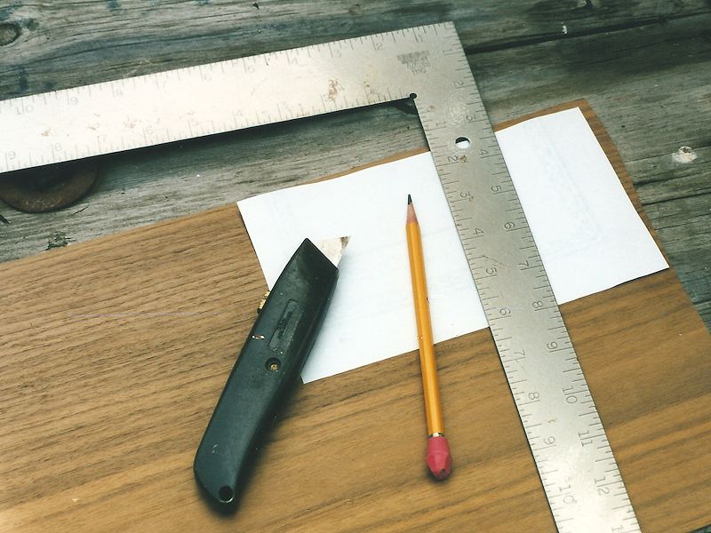
I made a paper template for the new piece, using a pencil and scissors. The next photo
shows the pattern on the veneer sheet, ready to cut. I traced
around the pattern with a sharp pencil and then carefully cut the veneer
with a craft knife, using the steel straightedge to guide the knife.

True to Murphy's law, the first piece of veneer didn't
quite fit! It was just a smidgen too small. I cut a second piece, leaving
a little more elbow room than before.
The second piece fit better, with just a tiny overage on all sides.
Removing the backing from the self-stick veneer, I carefully lined it up and pressed it
into place. Self-sticking veneer is convenient,
but you need to place it accurately the first time.
Once stuck on, this stuff stays where you put it!
I used a fine straight file and sandpaper to smooth the edges
of the veneer, matching its edges precisely to the underlying piece.
This is where it's nice to have a bit of overage.
To avoid scratching the cabinet top, I laid a thin piece of poster board
under the file and sandpaper. The sanding also removed
a few tiny bits of glue peeking out from the edge of the new veneer.
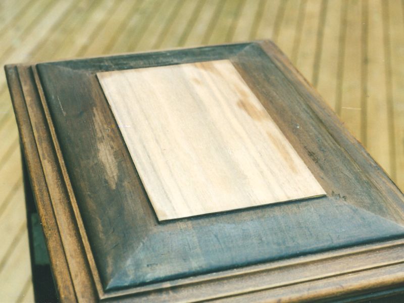
Now, I had a piece of unfinished veneer glued to a dark, unrestored cabinet.
I sanded the new piece with very fine paper and cleaned
it again with paint thinner. (In the next photo, the darker spots on
the new veneer are some paint thinner that hadn't quite dried when I took the shot.
I'm fanatical about keeping things clean while refinishing.)

To lend some character to the new piece, I gave it a couple of little
dents and dings, using the blunt handle of my old putty knife. When
the whole cabinet is done, the new veneer won't stand out by appearing
"too perfect."
I'm ready to finish the replacement veneer and refinish the
cabinet top.
Refinishing the Cabinet Top
As you've seen in the photos, the color of this cabinet is extremely
dark brown, almost black. Close inspection also showed that the various parts of
the cabinet were not all the same kind of wood.
It's common in cabinetmaking to put
expensive veneers only on the prominent surfaces and use cheaper woods for other
areas, and that's how this cabinet was made.
The beautifully grained front panel is made
of two matching pieces of veneer (probably walnut). A single sheet
was split in half and then the two halves were glued side-by-side to create a
symmetrical grain pattern. Other parts of the cabinet
have nondescript grain and appear to be an assortment of woods.
The old cabinetmakers used colored "toning" lacquer to give the whole piece
a uniform color and mask differences in wood types. I'll use
toning lacquer, too, after removing the damaged finish on top.
Only a light stripping job was needed. I wanted to remove the
damaged upper layer, but leave as much of the
original color and character as possible.
Citri-Strip is a stripper product that I use a lot.
It is an easy-to-control gel which doesn't contain environmentally-unfriendly
methylene chloride or give off harsh fumes.
To use a gel-type stripper, you pour a bit in a clean can (cat food
cans are ideal) and brush it generously onto the victim. The gel stays
pretty much where you put it and it remains liquid for a long time.
After the stripper worked for a few minutes, I checked
with my putty knife to see if the old finish had loosened. Then, working
very gently to avoid scratches, I removed the old gunk. This is a
critical phase in this type of stripping. If you start scraping too soon,
or scrape too hard, you can do more harm than good.
After most of the gel was scraped off, I switched to paper towels dipped in
paint thinner. Working quickly, I mopped away the rest of the
remaining stripper and loosened finish and then gave the whole top a final
wash with paint thinner on a soft, lint-free rag.
When I was done, the top was smooth and blemish-free, and it retained much
of its original color.
The next step was to match the colors. I began by wiping a coat of
walnut stain over the entire top, including the new piece. This evened out
the color of the stripped area and made the new veneer somewhat darker.
With only one stain coat, it was still too light, of course.
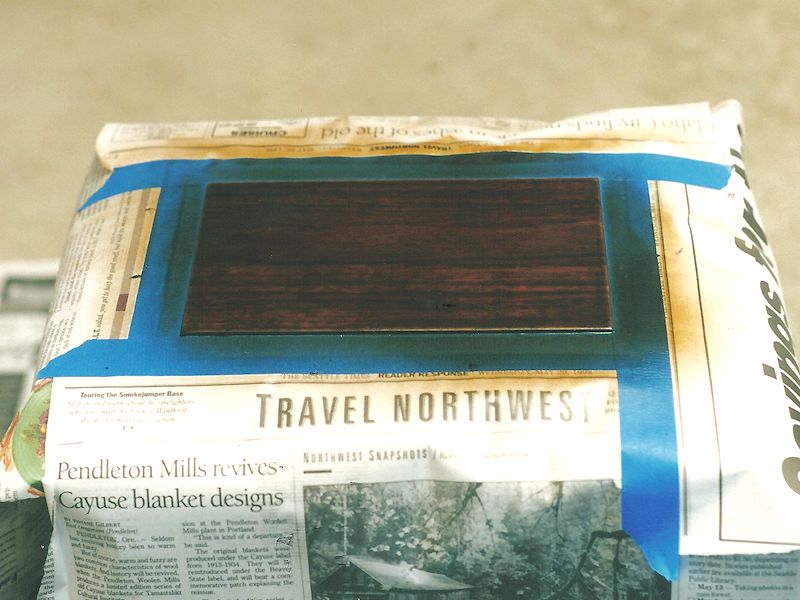
After the stain dried, I masked the area around the new veneer
with paper and tape, and sprayed on brown toning lacquer until the
color looked right.

As the above photo shows, the toning lacquer made the veneer pretty dark. When
I removed the masking, however, I could see that it matched the rest of
the cabinet.

The new piece blends in! Most folks will never notice that a repair was made.
Restoring the Cabinet Body
The main body of the cabinet looked decent, without major scars or chips in the finish.
A lacquer finish in this condition can often be refreshed by rubbing it with a
rag dipped in a mixture of lacquer thinner and retardant. The thinner softens the old lacquer
and the retardant keeps the thinner from evaporating too quickly. This gives
you time to respread the softened finish, eliminating surface chips and scratches.
Some people call this procedure "reflowing," and it takes a little
practice.
This treatment smoothed the finish but it also lightened the color in worn areas a
bit too much. I gently sprayed the lightest areas with more toning lacquer.
Now the color looks as it did when I bought the radio. Worn areas such as the top edges still
look somewhat lighter, as before, but the rest of the finish
no longer has ugly scars or chips.
The last step was to spray on two thin coats of clear lacquer, buffing out the finish after
each coat with super-fine (0000) steel wool. The result is a deep,
lustrous finish. Because the cabinet was never sanded or stripped of all color, it still
has plenty of character, showing various wear marks and subtle color variations. But now it looks
like an original piece that was well cared for, rather than the beat-up thing
that I hauled home from the garage sale.
Inside the cabinet, next to the hot-running audio output tubes, is stapled a small square of insulating material.
In case that pad contains asbestos, I sprayed it with two coats of clear acrylic finish, to seal it and prevent
any stray fibers from escaping into our home. Asbestos is nasty stuff, but this pad isn't exposed to any mechanical
stress, so sealing it should take care of any potential problems.
Cabinet Miscellany
When I got the radio, its decorative brass dial escutcheon had tarnished nearly
to black. I brightened it up with metal polish and applied
clear lacquer to retard future tarnishing.
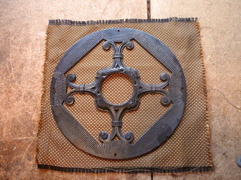
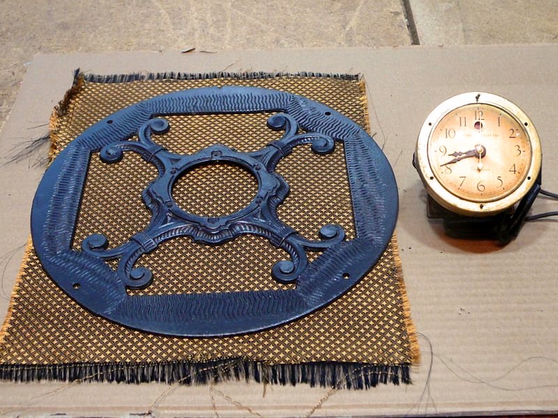
I also repainted the decorative metal frame that holds the clock in the center of
the grille. It had some noticeable corrosion that wouldn't polish away, so I sprayed
on a coat of grey that matched the original color.
I ordered a new grille cloth from Antique Electronic Supply,
which happened to offer an exact replacement. (In 1998, reproduction grille cloth
was readily available in many patterns.) After it arrived, I removed the old cloth and
glued the new one onto the back of the metal clock frame.

Another little touch was to cut small circles of felt and glue them
on the cabinet feet, in a couple of spots where the original felt
had fallen off. I had already cleaned up the clock, which worked
normally.
I'm not worried about the goofy missing handle. It's too small to securely lift
this heavy radio. That's why so many of these radios are missing
their handles: the mounting screws simply tear out of the top of the cabinet.
In my view, the handle looks out of place, anyway.
Fast Forward Fifteen Years
That's where things stood until 2013, when fellow collector
Bob Atchison asked if he
could borrow my metal clock frame. He wanted to make a mold from it and
use it to cast a reproduction. He was willing to pay me to rent the piece.
Since Bob also did electronic restorations, I offered to lend him the
piece if he would recap my chassis in return (finally—a way for me to get
my GE working without tackling those nasty capacitors!). We made a deal and he soon
returned the chassis fully restored. My glued-on grille cloth became
torn during removal, but I figured that a full restoration was well worth
a cloth.
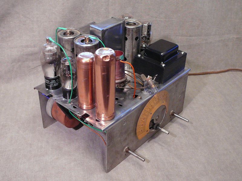
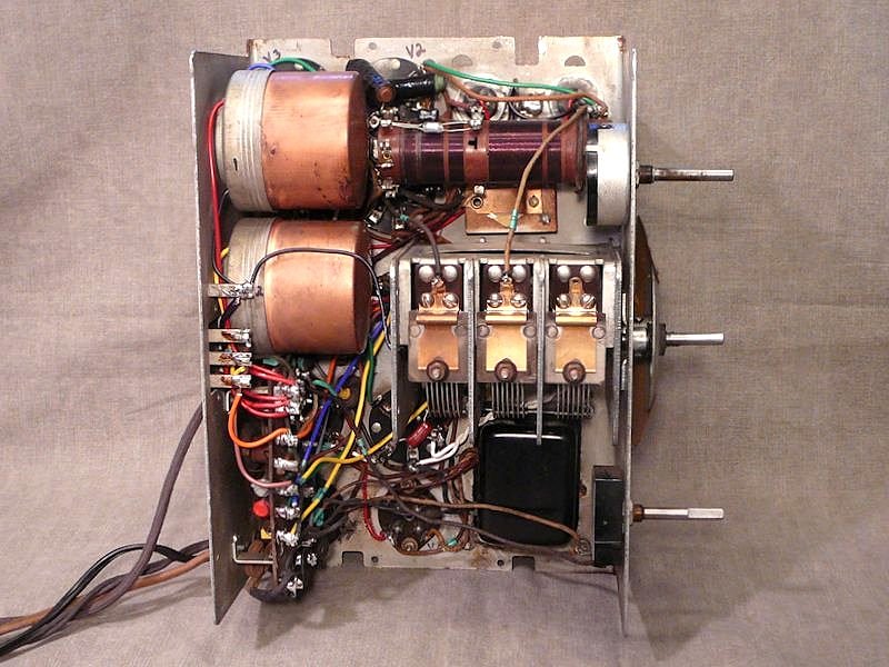
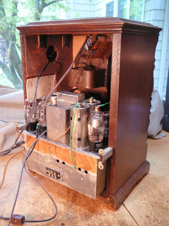
Here is the chassis after restoration. Bob replaced a number of wires
in addition to the usual capacitors and resistors. He also did a fine job of cleaning
up the chassis.
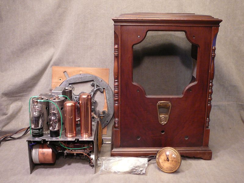
Finding the Missing Pieces
My project was nearing completion. Here are the components at this stage:

A few details remained: the radio was missing all three of its knobs;
I also needed to find a new grille cloth and install it.
During the intervening fifteen years, reproduction grille cloth had become hard to find.
The main supplier had ceased production and I couldn't find a substitute in any
of the retail channels.
A couple of queries to the Antique Radios Forum turned up these missing pieces.
I found original wooden knobs from a couple of fellow collectors, and a third collector happened to
have a spare piece of the same cloth that I had installed years earlier. (Thanks, Alan, Barry, and Mike!)
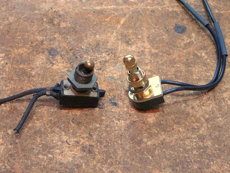
The original power switch finally gave up the ghost around this time.
I couldn't find an exact replacement with such a stubby switch lever, but this
new rotary switch will suffice for now. If the bright brass color annoys me, I'll
darken it with a quick rinse of gun blueing liquid.

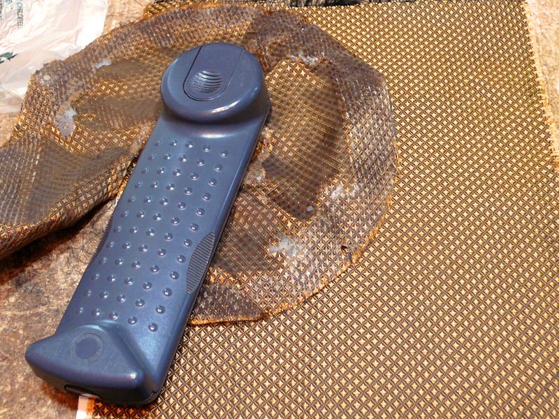
Grille Cloth Redux
Let's get that new grille cloth in place! The old and new cloths match perfectly—no surprise,
since they came from the same source.

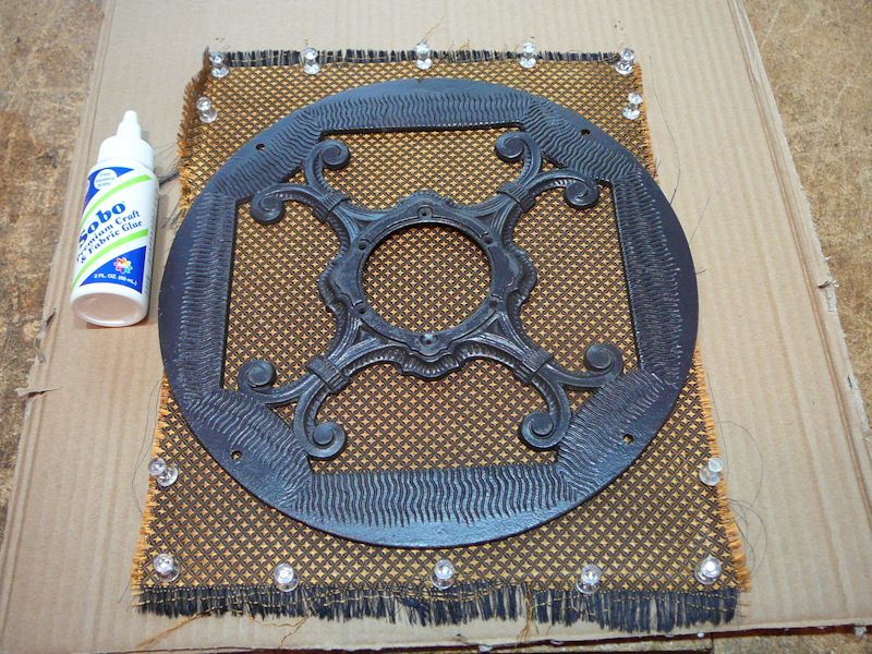
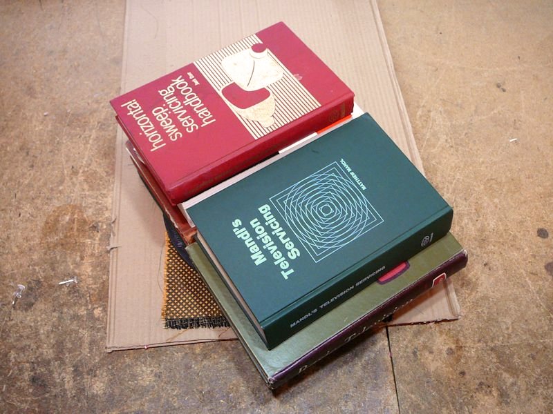
I starched and ironed the cloth before gluing it. Starch will help
it to hang tightly without sagging. In the next photos, I have pinned the cloth to a board,
applied glue to the back of the frame and pressed it down, and then put some books on
the frame while the glue cures:


I used fabric glue rather than spray adhesive for a couple of reasons. Spray adhesive
can be messy, and I needed to apply glue precisely to the frame's back side. Spray glue
also sticks almost instantly, leaving you no chance to adjust
the cloth a bit after application.
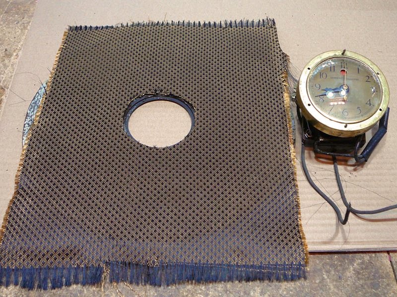
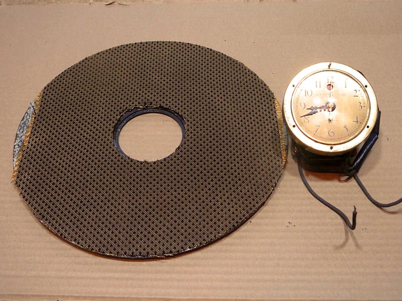
The next step was to trim the cloth around the frame edges and make a hole in the center for
the clock.
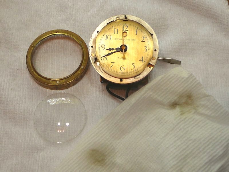
I had cleaned the outside of the clock glass years earlier. Now, I took a few minutes to
remove the glass and clean its inside as well as the dial face. I'm glad that I did!
This photo shows some of the grime that came off the inside of the glass.

The next photos show how I trimmed the cloth and installed the clock onto its frame.


In addition to trimming the cloth, I used an awl to gently poke holes wherever a screw
would pass through it. If you take this precaution, it's less likely that a screw will
grab a thread from the cloth and damage the pattern when you tighten it. You want each
screw to slip between the threads, not twist them up like a winch.
Final Assembly
It's time to install the speaker. The clock frame goes on frontmost, held against the cabinet
by the same four bolts that hold the speaker. Behind it lies
a cardboard shim and then the speaker frame. In the following photo, notice how
the clock's power cord comes out from a lower side, fed through a slot in the cardboard shim.

When you install the clock and speaker, take care that the clock's cord doesn't rub against
the speaker cone, which could create noise.
The speaker must be mounted as shown, with the terminals on top. If you mount it any
other way, its frame will hit the chassis when you slide that in, and you'll have to
remove it and start over.
The chassis is mounted with rubber-padded rails that slide into slots in the sides
of the cabinet. The rubber dampens vibrations that could cause microphonic oscillations
in a tube. Without that cushion, the radio might squeal or make strange reverberating noises
if you happen to rap the radio or walk heavily nearby.
Some form of microphonic damper is a common feature in older radios. For instance, the chassis in my
Zenith 12-S-471 is mounted on springs to absorb vibrations.
The chassis in my Zenith 12-A-58 and
Stewart-Warner 1865 rest on rubber gaskets.
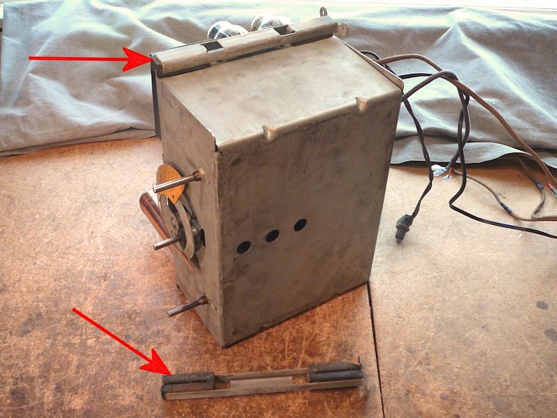
The next photo shows the chassis rails. One has been slipped onto the chassis and
the other lies on the workbench.

Notice how the under-chassis components are completely enveloped to keep out
stray RF (radio frequency) interference. Most radio chassis of the time did not provide such extensive shielding.
The final photos show how the chassis is installed. After I slid it all the way in,
I secured the rails to the cabinet with four screws.
When I wired up the clock, I installed a line switch on its power cord. There's no point
in running the clock 365 days a year. I'll run it every once in a while, to keep
things lubed up, but I don't want to wear it out when nobody's around.
Final Thoughts
What a relief to complete this project after so many years of inattention! At last, this
handsome radio can escape the workshop and take its place in our home, where it can be
used and enjoyed. I like its classic lines, and the clock provides a unique focal point.
With a nice long antenna, it plays well, too.
|