Sony Model KV-4000 Miniature Color Television (1980)


Introduced in 1980, Sony's KV-4000 television is a wonder of miniaturization, producing a stunning
color image on a 3.5-inch screen.
The secret to the KV-4000's picture is a Trinitron tube (type 110LB22). Unlike older color tubes,
which used colored dots, the Trinitron
used colored vertical stripes, or phosphor bars, to produce an unusually bright picture.
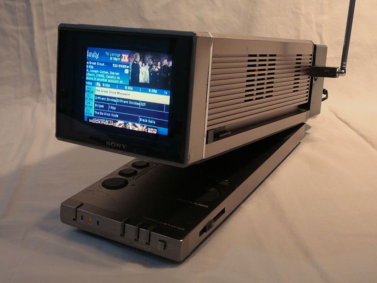
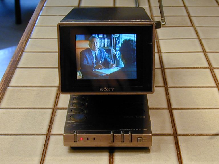
Here are photos of my KV-4000 receiving a cable TV broadcast:

The KV-4000 receives the standard VHF/UHF channels and it offers either manual or automatic
electronic tuning. It can operate on AC using its built-in AC converter or 12-volt DC
from a source like Sony's optional battery pack. It can also accept external audio and
video, letting you hook up a DVD or VHS player, cable TV, or a digital TV converter.
Nice Picture, but . . .
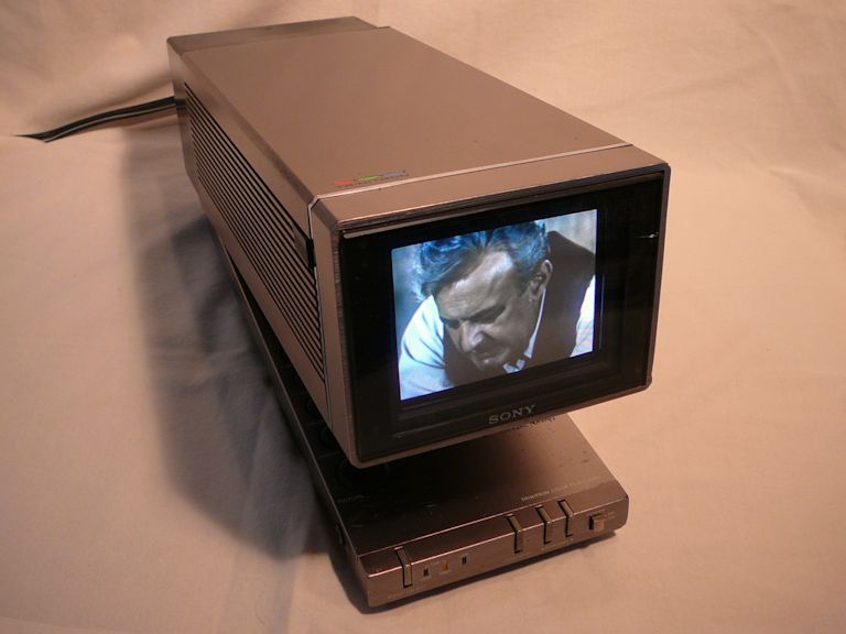
I bought my KV-4000 in 2010. Here's the TV as found:

Yes, the picture looked fine, but the TV wasn't fully operational. Look at the bottom left
of the lower panel, and you'll see a little red light. It is lit to show that the TV is receiving
the low VHF band of channels.
On this TV, you press a little Band Select button to switch between low VHF (channels 2-6),
high VHF (7-13), or UHF (14-83). After you choose the band, you can pick any channel in that range,
using either manual or automatic tuning.
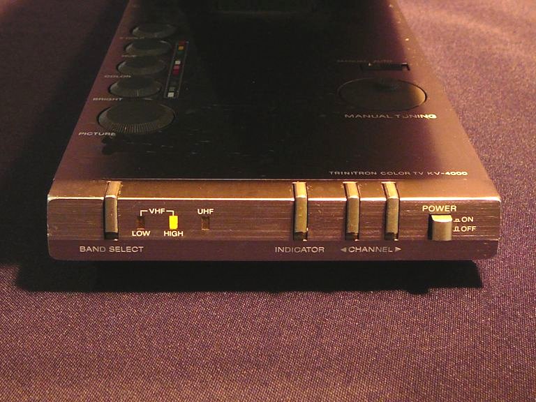
The next photo shows the Band Select button and three
others of the same type (Indicator, Channel-down, Channel-up):

In that photo, which was taken after I repaired the TV, the High VHF lamp is lit, but when I
bought the TV, all four pushbuttons on that panel were inoperative. I couldn't
use anything beyond the low VHF range of channels. Automatic tuning was also disabled,
since I couldn't scan for channels with the Channel-down or Channel-up buttons.
Low and High VHF Channels
The division of VHF TV channels into low and high groups wasn't an arbitrary whim of Sony's.
The FCC created these groups when it allocated channel frequencies in the 1940s.
The low channels (2-6) were given the frequencies from 54-88 MHz (megahertz) and the high
channels (7-13) were given the band from 174-216 MHz.
This left a gap between the "top" of channel 6 at 88 MHz and the "bottom" of
channel 7 at 174 MHz.
What goes into the gap between channels 6 and 7? A chunk of that space is allocated to FM radio,
which in America stretches from about 88-108 MHz. It's like a frequency
sandwich: FM radio is the slice of ham between two slices of TV bread.
Early DuMont TVs with continuous tuners took advantage of this arrangement.
The same tuner could bring in both TV and FM radio, without a lot of extra engineering. You
can read more about such continuous tuners in my
RA-103 and RA-113 articles.
Who Cares About Those Buttons?
For a few years, I didn't care that those four little buttons didn't work, because I used
the TV to receive programming on channel 3 from my in-house TV transmitter.
When you turn on the KV-4000, it goes to low VHF channels by default, so I left it permanently tuned
to channel 3 and everything was hunky-dory.
Enter the RFI demon. Like many modern homes, ours is full of RFI (radio frequency interference) from
sources like fluorescent lights and computer power supplies. I learned recently that high VHF
channels are less susceptible to RFI than the lower ones. Switching my in-house
transmitter from channel 3 to a high channel (specifically, 12) immediately
improved the reception quality in RFI-prone parts of the house.
The improvement was even more dramatic in our garage, where simply turning on
the fluorescent lights used to blitz all reception.
That's when I remembered that the buttons on my KV-4000 didn't work! The dead Band Select button
prevented me from choosing the higher, interference-free channel, even in manual tuning mode.
I posted a query in the Videokarma solid-state TV forum
and discovered that the "tactile" switches used in this Sony are notoriously failure-prone.
Many KV-4000 owners have the same problem and these sealed switches cannot be cured by cleaning.
Replacement is the only option.
At that point, one of the Videokarma members kindly offered to send me some switches that he had
gotten to repair his KV-4000. He mailed me some spares and I decided to attempt the fix.
This TV is simply too nice to abandon as a non-working "shelf queen."
Replacing Defective Pushbutton Switches
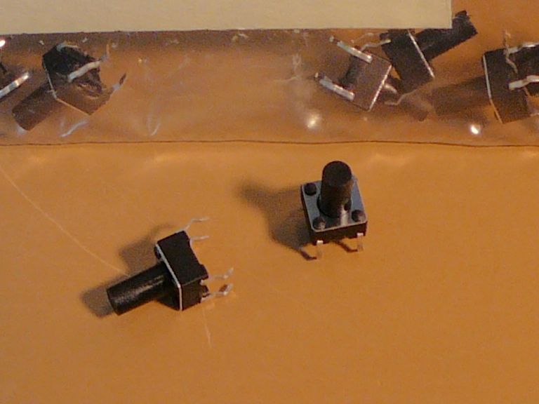
In a few days, the replacements arrived. As you'd expect in a miniaturized TV like this,
they are tiny—no bigger than a pencil eraser.

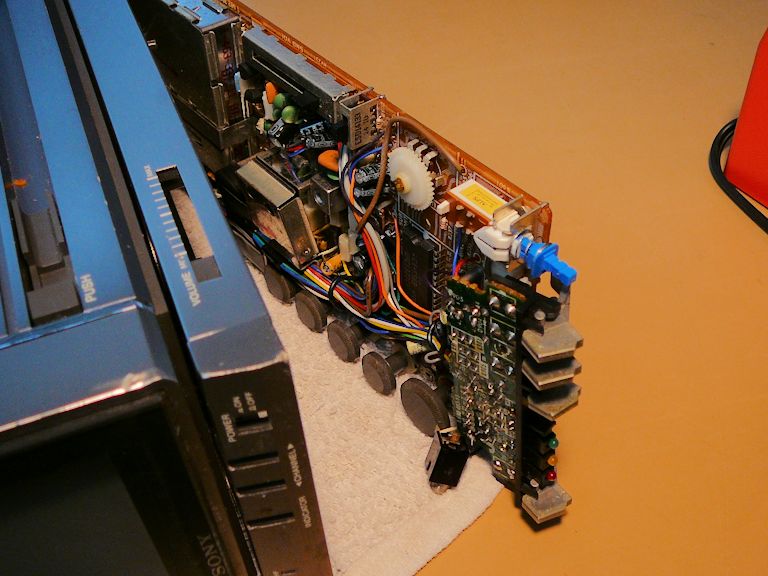
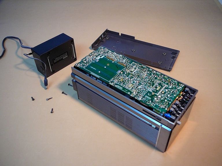
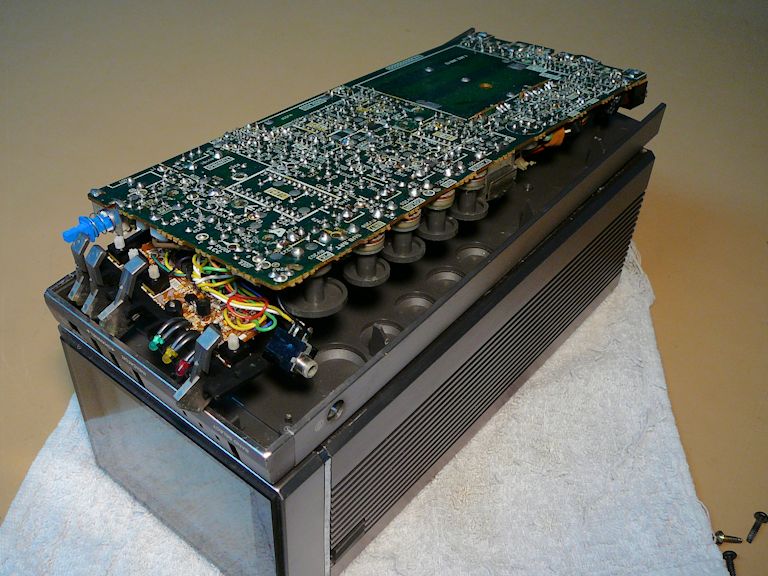
Let's dig in and see what this repair will involve. In the next photo, I have removed the
bottom cover from the TV, exposing the bottom main PC board. To the left is the
AC converter that I unsnapped from the back of the cabinet.

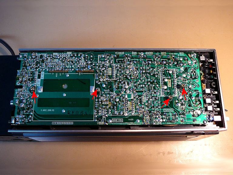
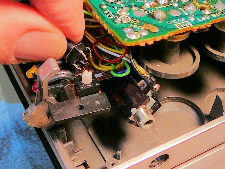
Below is a closer view of the big board, which I'll lift to access
the switches. In this view, the switches are to the right; their mini-board
is sandwiched underneath the big board:

Four screws secure the big board from the top and they are marked with red arrows in the previous photo.
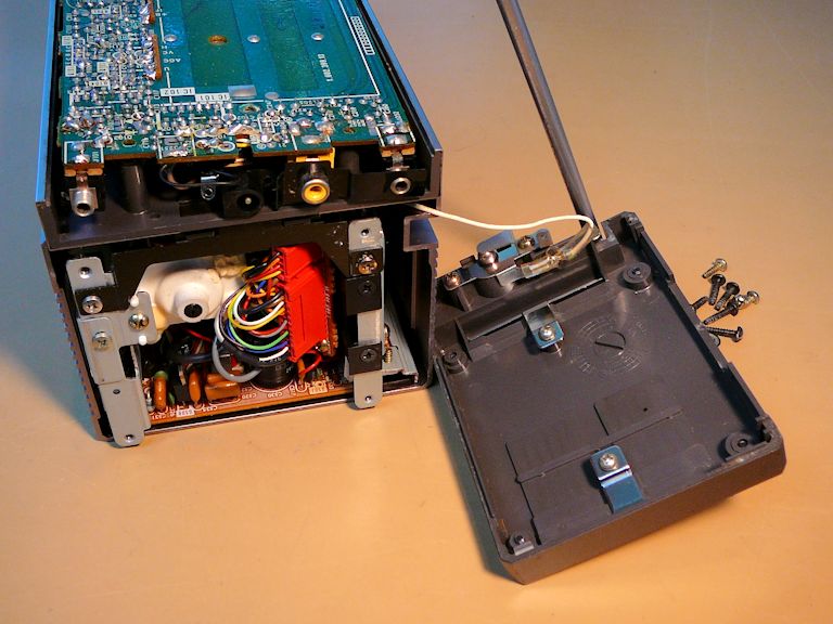
Two multi-strand cables run below the board and connect it to the top half
of the TV. I'll need to make some slack in those cables to lift the
big board. Removing the back cover exposes two red cable connectors:

Before freeing the big board, I looked closely at how the pushbutton switches work. This animated
GIF shows one of them in action: the button outside the cabinet is actually part of a lever that moves the
little momentary-contact switch up and down:
(In that view, the TV is lying upside down on the workbench. In normal operation, pushing down or inward on the button
moves the lever up to actuate the switch.)
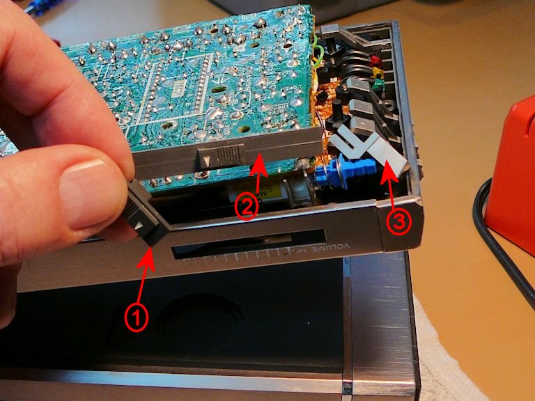
Detaching the big board from the cabinet was a bit of a puzzle. Obviously, you need to remove the
mounting nut from the earphone jack on the side. You also need to carefully pry and wiggle out
various other bits, including the detachable end of the push-on/push-off power switch and the sliding tab for the volume
control. The next photo shows some of those parts.

In that photo, 1 shows the slider for the manual/auto tuning switch, 2 shows the volume slider,
and 3 shows the end cap of the on/off switch, which I temporarily removed.
As you lift the board, you may find that other parts fall out, such as the manual tuning knob.
When disassembling this TV, pay attention to loose
stuff and make sure you know where and how to put everything back.
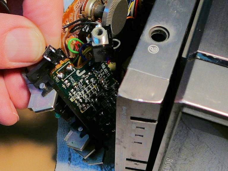
The next two photos show the big and small boards being loosened. The small board is held on by two
tiny screws and it can't come free until you lift the overlapping big board:

At last, I could examine the old switches and compare them to the replacements. In the first photo, rectangle
S901 contains the terminals for the Band Select switch. The second photo shows that switch from above its board:


The switches were similar in size, but the new ones had four terminals while the old ones had two.
In the Videokarma discussion, I learned
that two of the four terminals are duplicates. One forum member suggested clipping a pair of terminals
from the new switch and turning it 45 degrees for mounting.
Mounting the switch at an angle was a clever suggestion, and the board has just enough elbow room to
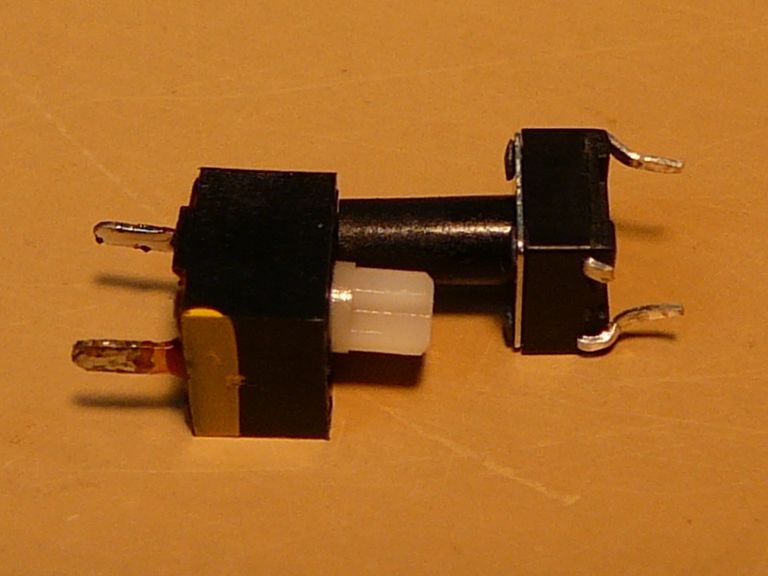
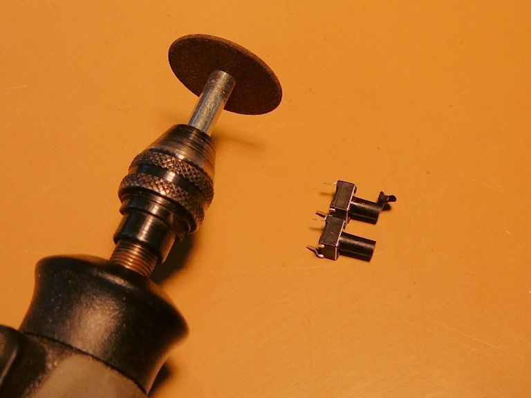
enable that. The next photo shows an old and new switch together. On the new one, I have
clipped two terminals on opposite corners and bent the remaining terminals slightly inward to
fit the board holes:
That photo also shows the relative height of both switches. The new one has a shallower base, but its
shaft is longer. To avoid a too-tight fit, I trimmed about 1 mm from the end of the new switch:

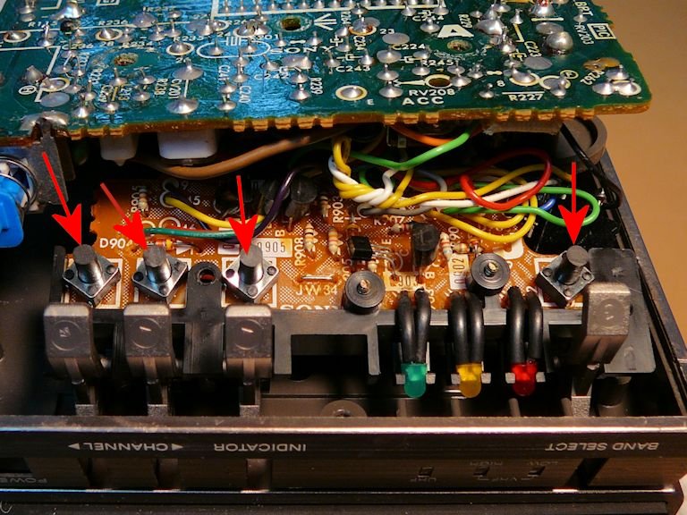
I'm not crazy about working with such small components, but with some care and patience, I managed
to replace all four switches. The new ones are labeled with red arrows in the next photo. Notice how
their bases are mounted diagonally, not square-on like the originals:
I tried not to rush when I put the set back together. You don't want
to crack the PC board or break some little irreplaceable widget by forcing things.
To my delight, the repair worked! Here is the KV-4000 receiving on channel 12 (note that
the High VHF lamp is lit).
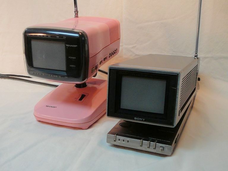
Time for a TV Party!
Just for fun, I hauled out my other 3.5-inch color TV, a Sharp 3SL6.
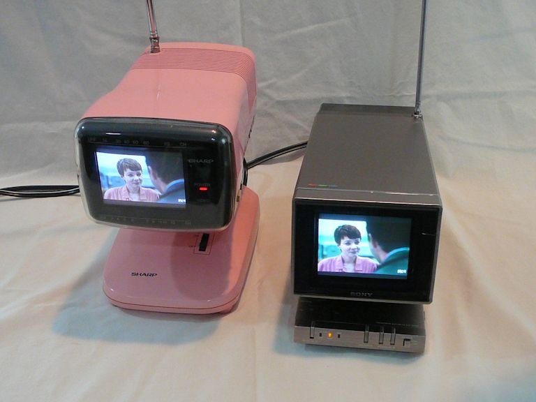
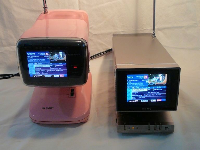
These photos show the two sets side by side, receiving a broadcast from my
in-house transmitter on their rod antennas:


My camera makes the screen images too blue, but you get the basic idea. Both TVs produce a crisp, lively color
image with plenty of brightness and contrast. The 1980 Sony looks at least as good as the 1986 Sharp,
which had an extra six years in which to develop.
It looks like the Sony's image needs some minor tweaking; the image is slightly off-center horizontally,
and perhaps a bit too wide. The bottom of the TV has no such adjusters, so I assume they're lurking somewhere inside
the top. Perhaps I'll try those adjustments if I ever track down a KV-4000 service manual
(email me if you have one).
Final Thoughts
This was a very satisfying project. My little KV-4000 has a new lease on life and it has returned
to its place on our kitchen counter. If I tune the in-house transmitter to the same channel as our
flat screen TV in the neighboring family room, everyone can enjoy the same program in adjacent rooms.
Thanks again to the Videokarma forum members for their advice, especially Electronic M, NoPegs, and
WISCOJIM who sent me the free parts. Without their help, this set likely would have ended
up on a back shelf.
If you know of a source for new switches, send me an email. It would be nice
to post that information here for other KV-4000 owners who have the same problem.
|