Sharp Model 3LS36 Miniature Color Television (1986)


The Sharp 3LS36 television has a quirky design and a tiny color screen.
It's the sort of TV that people either love or hate at a glance. Mine
happens to be bright pink, and I like it a lot.
Description
Introduced in 1986, the Sharp 3LS36 is a marvel of miniature engineering
and it performs very well for such a tiny set.
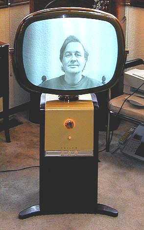
It's interesting to compare the Sharp with my 1958
Philco Predicta.
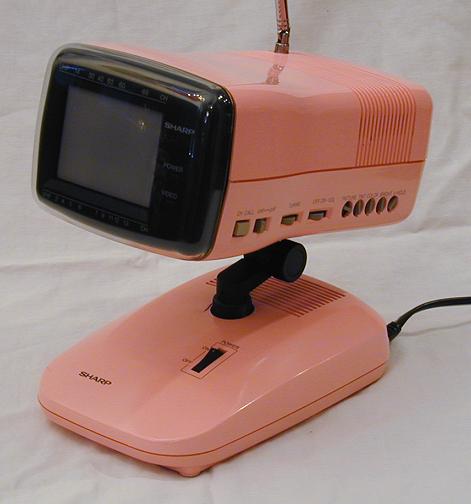
Both TVs have a pedestal design, with a screen that can swivel back and forth.
In the Predicta, the picture tube is separate and the entire television chassis is
contained in the cabinet below. The Sharp, on the other hand, contains the entire tuner/receiver
chassis in the upper portion.
This TV came in other colors, including black, but in my view, the
"Pepto-Bismol" pink edition is the coolest.
The base, or lower portion, contains an AC power supply,
which connects to the upper case through a flexible cable. If you want, you can detach the
upper part from the base and power it with a 12-volt DC source. The base adapter is listed
as an optional accessory in factory literature, but it's hard to imagine anyone actually
bought the TV without it. Besides supplying power, the base allows you to tilt the screen
for convenient viewing, rather than laying it flat on a table.
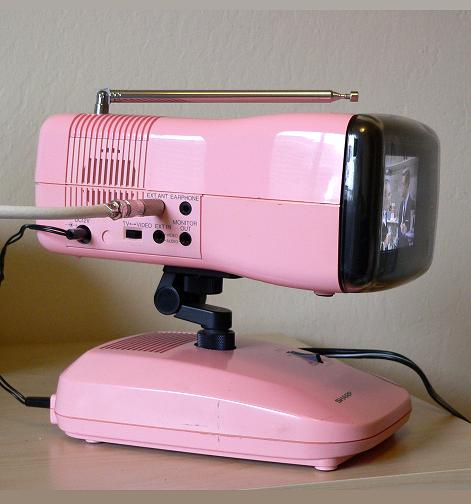
The Sharp has a surprising number of input/output connections for such a small TV.
You can use it with an external antenna, plug in an earphone, or even watch
a movie using an external source such as VCR or DVD player.
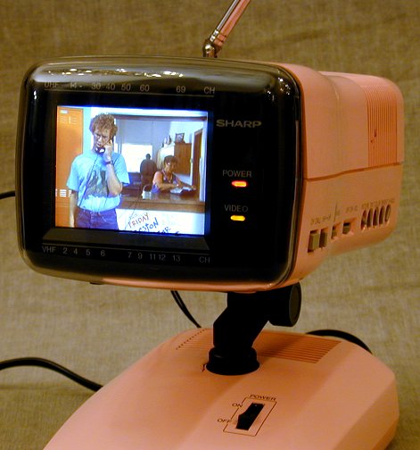
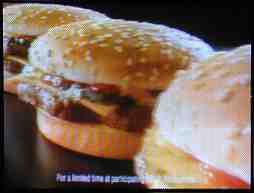
The next photo shows the restored Sharp playing the movie Napoleon Dynamite from a DVD.
The picture quality on this miniature set is outstanding . . . if you get close enough
to see it clearly. I have often used it as a bedside set, watching
late-night TV with headphones after my wife has gone to sleep.
A note regarding the photos. I found it difficult to get the colors right using my
automatic-everything digital camera, which tends to make the cabinet look too orange
when the TV is playing. The most accurate representation of the cabinet color is in
the photo showing the input/output connections on the side of the TV.
Several years after I first published this article, a fellow collector gave me
a copy of the factory service manual. To download it, right-click on the following
icon and choose Save Target As...
Restoration
The restoration story for this television covered a lot of time and territory by the
time it was finished. I bought the TV over the Internet from a seller who stated that
the case had no cracks and the television "worked perfectly."
Famous last words. When I received the set, I discovered that the bottom case was
broken around the gooseneck stand. Either it was broken in the first place, or
it broke because the seller shipped it standing upright in a flimsy box with little or no packing.
Okay, at least it's mostly in one piece. I propped up the half-broken set and plugged it in. Nothing.
No picture, no sound, nada. Investigation revealed that the original power cable,
which connects the lower power supply to the upper tuner/receiver, was either broken or
internally burned out, and in any case, unrepairable, since it is encased in heavy molded plastic.
Okay, the seller couldn't possibly have tested the TV, but perhaps it works anyway.
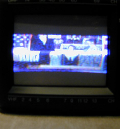
Hope springs eternal! I built a substitute power cable and again tried to power it up.
Here's the result.
On the plus side, the CRT was not a dud, I could see colors of a sort, the
tuner worked, and the sound was fantastic. On the minus side, the picture
was severely squished in the vertical direction. So much for "working
perfectly."
The TV passed through more than one set of hands in the process of restoration,
so let's take them in order, starting with me, Repairman Number 1.
Repairman Number 1
Time to open it up. In older tube TVs, vertical
problems are very common, and frequently caused by (duh) old
capacitors. Glancing at the schematic, I noticed some electrolytic capacitors
in the vertical circuits, which might be prime candidates for replacement.
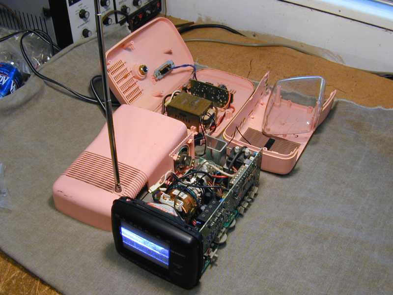
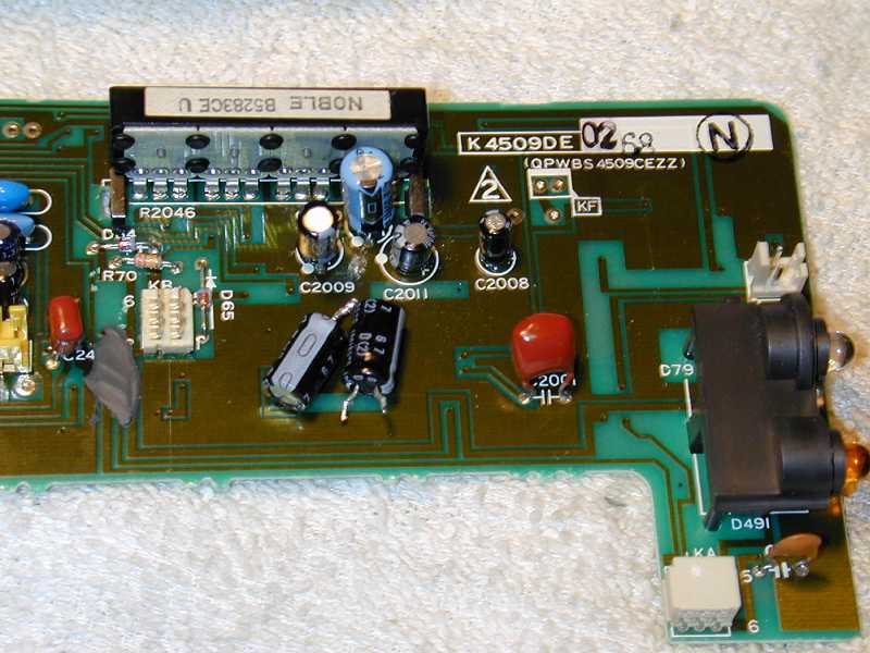
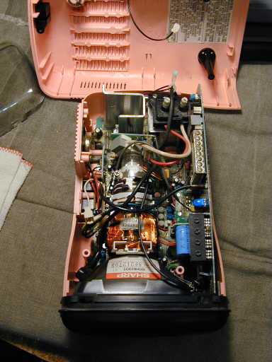
Here's a view into the tuner/receiver chassis. Tightly packed! The main PC board is below the
picture tube, with smaller boards mounted vertically on the sides.
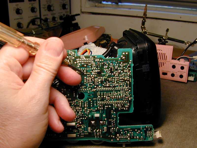
As with many consumer electronics of this era, getting inside the cabinet is a bit
of a pain. After loosening the case screws, you have to gently pry the case pieces
apart, taking care not to break the little plastic pressure tabs that hold it together
even after the screws are removed.
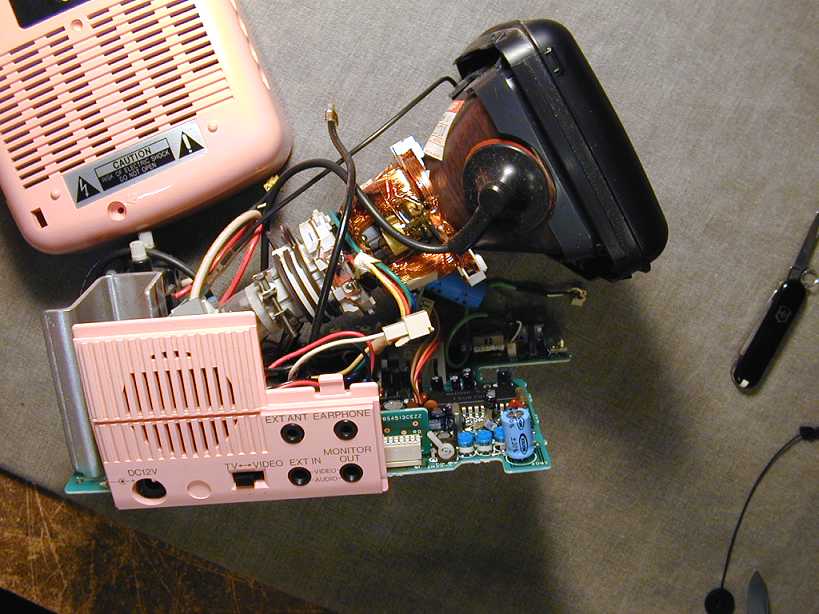
Here is the TV with the chassis fully removed. You can operate the television
in this state, as long as you keep your fingers well away from high voltage sources.
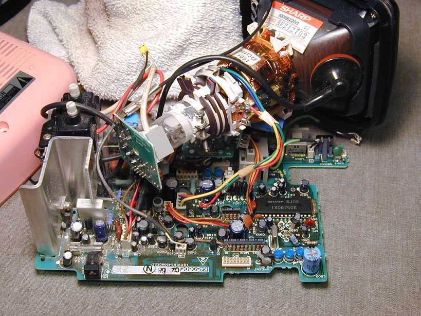
Reaching the electrolytics in the vertical section was a trip for me,
since I was familiar with much older tube electronics, which are huge and widely spaced by comparison.

Simply locating the component you want to replace is a challenge on
this kind of PC board.
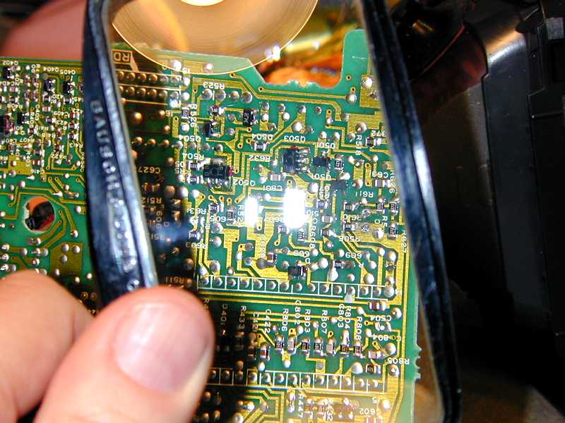
I used a magnifying lens and strong light to get a better view. This TV
uses a large number of miniature "surface mount" components—often
smaller than a grain of rice!
Here I have unplugged one of the side boards and replaced two electrolytic
capacitors in a vertical circuit.
After replacing a third electrolytic, I tried the TV again, and found
no improvement in the picture.
Repairman Number 2
Okay, I'm done. I don't have the experience or the right kind of equipment
to fix this kind of television.
Time to call in more muscle! I packed up the TV and shipped it to a friend
in a nearby state who has a lot of experience repairing radios and TVs both
old and new. He worked on the set for some time, even calling in a pal of his
with more solid-state experience. They finally threw in the towel, noting
that some vertical circuitry was contained in a "jungle chip," a
custom multi-purpose integrated circuit that is no longer available.
They repacked the TV and shipped it back to me. At this point, I thought I was
dead in the water, unless I could possibly find a junker TV of the same model
with a bad case or CRT, and try swapping out boards in hopes of a miracle.
Repairman Number 3
Not long after that, someone who had read one of my questions in an online forum
offered to fix the TV. Once again, the TV was packed up to
travel, this time to the Midwest.
This chapter of the repair story did not end well.
I shipped the TV to him in February, and, after a long interval of waiting for news,
spent several more months sending emails and letters
and leaving voicemail messages to ask whether he intended
to try fixing the set at all. I also heard from a couple of other TV collectors who
were in the same pickle, with their TVs his hands and apparently no intention
that anything would be fixed or returned.
Finally, after sending a letter to the local police chief, I convinced the
"repairman" to simply send the unopened package back, using the prepaid
return shipping label that I had provided.
The package arrived back home in one piece and
sat in my workshop for a while. This was pretty discouraging.
Repairman Number 4
Enter Andy Cuffe. After I whined about my predicament in an online forum, Andy
contacted me and offered to try his hand at the job, noting that he liked
the challenge of trying to fix things that others considered unrepairable.
With little to lose at this stage, the little pink TV made yet another 1500 mile trip.
One day after receiving the TV, Andy had it working perfectly!
Here is the story in his own words.
Phil,
Good news on the TV. It's now working like new.
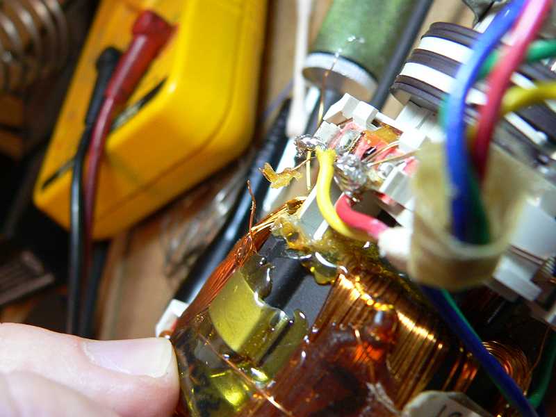
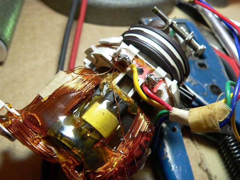
To cut a long story short, the yoke was bad, but I was able to repair
the yoke.
Now for the details...
First, I compared things to the schematic and noticed that the vertical
saw tooth wave form was highly distorted at the yoke and at the vertical
drive output from the jungle IC. I also noticed that those voltages on
pins 15 and 13 of the jungle IC were way off.
After throughly checking the vertical output circuit and not finding
anything I took another look at those suspect voltages. The voltage on
pin 15 (the feedback pin) was labeled as 8.7v, but there was nowhere for
that voltage to come from other than inside the IC. It would be unusual
for a feedback pin to supply current to a circuit. Also, since this pin
was grounded through a 680 ohm resistor, it would be a lot of current.
The vertical drive output from pin 13 was labeled as 6.8v, but if it was
6.8v the vertical drive transistor (the one you replaced) would be
driven into saturation and not pass the vertical drive signal at all.
It turns out that those voltages should have been labeled 0.87 and 0.68
and that they were correct the whole time!
I was still confused by the distorted vertical signal. One odd thing
was that the picture wasn't filling the screen even though the vertical
output transistors were being driven to clipping. Even if distorted,
the vertical circuit was giving as much signal as it possibly could, so
it should have at least filled the screen.
Next, I disconnected the vertical yoke and tried feeding it a 60 Hz
sawtooth from my signal generator. I found that the picture was still
collapsed across the middle, but if I moved it up, or down with the DC
offset, it looked ok.
I disconnected one end of the two parallel halves of the vertical yoke
winding. One of them was open circuit, but fortunately after a little
digging I found the break right near one end. There was enough slack to
simply solder the new end to the terminal strip on the yoke.
After reassembly and a little adjustment it was producing a good picture.
I also repaired some cracked plastic in the base where the metal
mounting attaches. I'm not sure if this happened in shipping to me, or
before that. It's made of ABS plastic, so a little super glue provided
a strong repair. Just to be safe, I reinforced it with some plastic
epoxy. There's a small visible crack, but it's not too noticeable. The
metal mounting bracket should be removed from the base for shipping.
I'd like to test it for a few days before I pack it up and return it to
you, but unless something else goes wrong, it should be on its way this
week.
Andy Cuffe
Here are Andy's before-and-after photos of the repair.
Wow!
What can I say . . . you gotta be impressed with a repairman who
not only solves the problem, but also fixes things you didn't ask
him to fix (the broken case).
Final Thoughts
After several cross-country trips and various attempts, the long
saga came to a happy end. This final snapshot that shows the accurate color rendition
of the tiny TV.
So, kids, what did we learn?
Something I have known for a long time is that you can never be
too careful with packing when sending electronics long distance.
Before bidding on this TV, I referred the seller to my article
on packing old radios and asked whether
he would pack the TV that way. He said yes, but that was a lie.
His poor packing job caused damage to the lower case, but at least I tried!
I don't know what more I could have done, short of driving cross country
to pick it up in person.
I thought it would be fun and informative to work on a type of TV
that I had never attempted before, and I certainly learned some useful
things about working on this kind of modern solid-state device. I also
learned that I was in over my head when it came to fixing a non-obvious problem.
Never be afraid to ask for help. In hindsight, it's a good
thing that I quickly recognized I didn't have the right equipment or
expertise to fix this TV. Nobody knows everything, after all. I was lucky to
find a couple of pals willing to help with the problem, and one of them
eventually solved it.
These TVs are fairly common, so it should not be difficult to find one, if
you're interested. If you buy one at long distance, the seller should ideally
separate the top and bottom pieces before shipping. All you have to do is
unscrew the metal collar on the gooseneck that connects the two cases, and
unplug the power cable that runs between them. If even that is beyond
the seller's ability, he should lay the TV on its side in the box, so that
the weight of the upper module doesn't break the bottom case.
I love radios and TVs with unusual cabinets. Besides
the Predicta, mentioned earlier, I own a "space helmet" shaped
JVC VideoSphere television, a
pyramidal JVC Video Capsule television,
Colonial and Sonora
radios in the shape of world globes, a Trophy Baseball set
shaped like a baseball, a Weltron 2001
"space ball" radio/8 track set, and even a Suntory
whiskey bottle transistor.
|