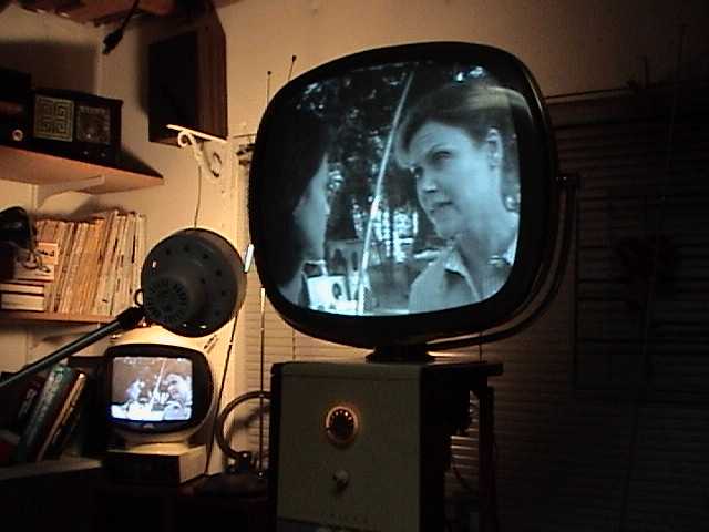
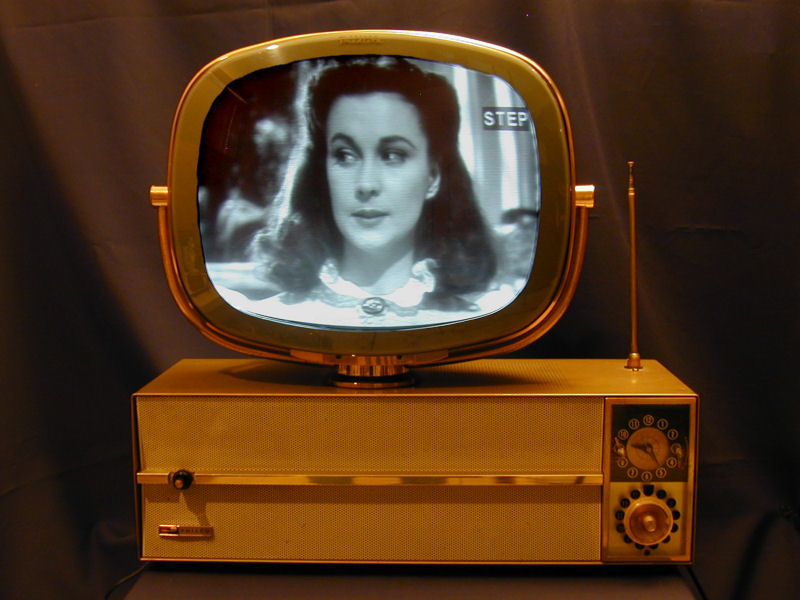
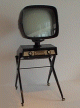
Philco Model 4654 Predicta Television (1958)


 Movie 1
Movie 2
Movie 1
Movie 2
Is this the ultimate TV? Love it or hate it, the Philco Predicta television
is unarguably one of the design icons of the 20th Century. Collectors cherish the Predicta
for its "space age" look, but restorers grumble about its hard-to-service
innards.
Philco produced the Predicta from 1958-1960. Several models were available,
in console or tabletop cabinets and with 21-inch or 17-inch screens.
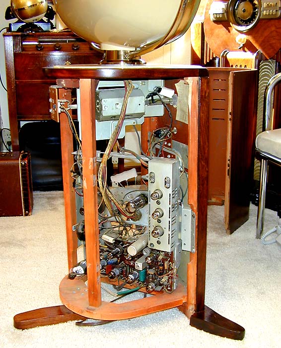
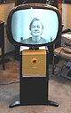
This console style was called the Pedestal and it was sold in 1958.
The top is painted yellow and the rest of the cabinet has a mahogany finish.
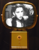
The first photo shows the TV playing at the time of purchase.
My set has a VHF tuner for channels 2-13; some Predictas had a UHF tuner, as well.
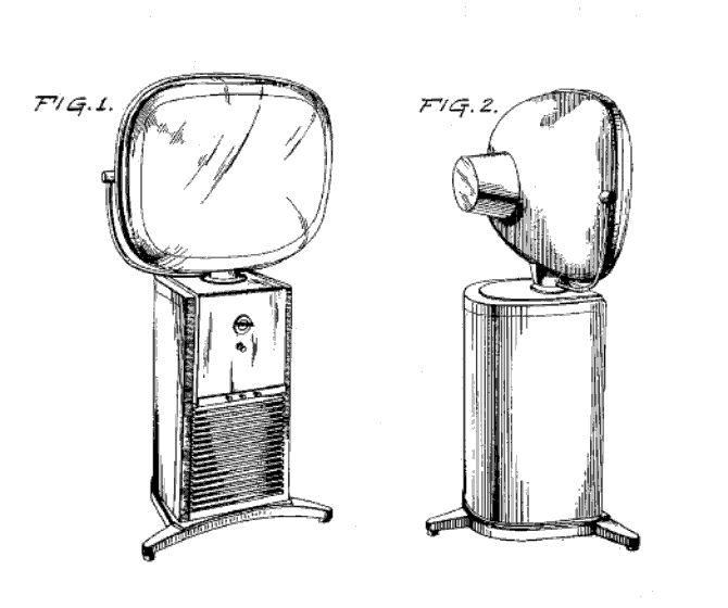
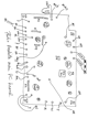
The Pedestal cabinet was created by Catherine Winkler and Richard Whipple. Philco patented
the design in 1958, in US Patent
D183,782, whose drawing appears here:

The 1958 line also included the Holiday, the same TV in a low wooden tabletop cabinet.
Another 21-inch console, the Penthouse, had a lowboy wooden cabinet and a movable
screen attached with a long cable. I never quite saw the utility
of this scheme for home use. How often would you want to lug a heavy CRT around
your living room to a different location? I've read one suggestion that it was handy for
bars, where you could put the screen close to customers but keep the channel changer
out of patrons' hands.
The most common Predictas were 17-inch tabletops, with metal
cabinets in a choice of colors. Introduced in 1959, two of these sets were
named Princess and Debutante. A third model, the Siesta, had a
clock that could turn the TV on and off at a designated time.
About a dozen years after buying this pedestal set, I got a second Predicta,
a gold Siesta, which you can read about in
its article.

The last upright Predicta, sold in 1960,
was the Continental. Its profile was similar to the Pedestal, but the
cabinet had a Danish Modern design with four finned supports
attached at an angle to the central box.
The free-standing picture tube is almost unique in the history of TV design.
The German Vega company produced a tabletop model that looks much like a tabletop Predicta.
I have seen photos of that set, but never seen one in the flesh.
The closest (perhaps the only) lookalike to the upright Predicta
was the 1957 Teleavia from France.
I took this photo of a Teleavia
at the Musée National d'Art Moderne in Paris.
The magazine has a Teleavia article with
more photos.
Despite the radical styling that endears it to collectors, the Predicta had an
unhappy history in the field, causing some
to dub it the "Edsel of televisions." Quality control was poor, leading to an excessive
number of returns and warranty service calls. The Predicta's PC (printed circuit) boards
were difficult to service and suffered from overheating.
Some people blame the Predicta for the demise of Philco, but that's an urban
legend. Philco was a large, diverse company, and made many other console and portable
TVs which were reliable and sold well.
Predictas were very popular in their day and many thousands are still in
circulation. Due to this ready availability, no Predicta model, including
the Continental, is especially rare or valuable from a TV collecting perspective.
Rare or not, a properly restored Predicta is certainly fun to own. Mine has logged
many hours since I got it. I love to watch that big, bright screen floating in space.
First Look
I had wanted a Predicta for years and when
this nice example popped up locally, I just had to have it.
The TV was "working" when I bought it, although the seller had
handed it to a local repairman who did only the minimum needed
to make it play. The initial photos show a bright, clear picture.
That photo shows me looking into a camcorder whose output was piped to the Predicta.
Broadcast reception left much to be desired. The vertical
hold was unstable, requiring careful adjustment whenever you changed
stations or when the picture content changed significantly (for example, from a
low-contrast to high-contrast scene).
When not rolling, however, the picture was quite watchable, indicating
good overall health. The camcorder's output produced diagonal stripes, a result often
seen when sending signals from a modern device to an older TV. To make
decent photos in a bright room, I had adjusted the gain control differently than
you'd want for normal viewing, which accentuated the "stripies."
The vertical linearity was a bit off, causing the top half of the
picture to be vertically stretched, while the bottom half appears squished.
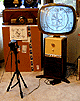
The next two photos show the homebrew setup that I used to adjust the linearity and
some other picture controls. In the first photo, you can see a video camcorder on
a tripod, pointing at a printout of the classic "Indian Chief" test pattern.
The output from the camcorder was piped to an RF modulator, which was connected
to the TV's antenna terminals.
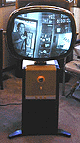
The picture's not bad, for an unrestored TV. The circles look, well, circular.
Vertical and horizontal centering need adjustment, as well as the horizontal linearity.
The squares on the left side of the screen are wider than those on the right.
You might not notice these issues in normal viewing, but of course we
want the picture to be as accurate as possible.
The funky camcorder setup was the best I could do about 20 years ago when restoring this TV.
Now that I have more TV experience, I use a pattern generator like the one shown below.

A cheaper alternative is to make a test pattern DVD
as explained in my RCA CT-100 article.
The Predicta screen is encased in a clear safety cover, which is made of
soft, easily damaged plastic. Mine was in pretty nice
condition, with only a couple of visible boo-boos. The Philco Predicta
lettering on top of the cover was still in excellent shape. Also in good
condition was the oval cover for the rear of the picture tube, as well as
the brass bezel and support arms which steady the massive CRT.
This is a heavy, awkward television to move around. It is best done with two people,
one supporting the CRT and the other the cabinet. Be careful not to break one of
the legs by slamming it down at an angle.
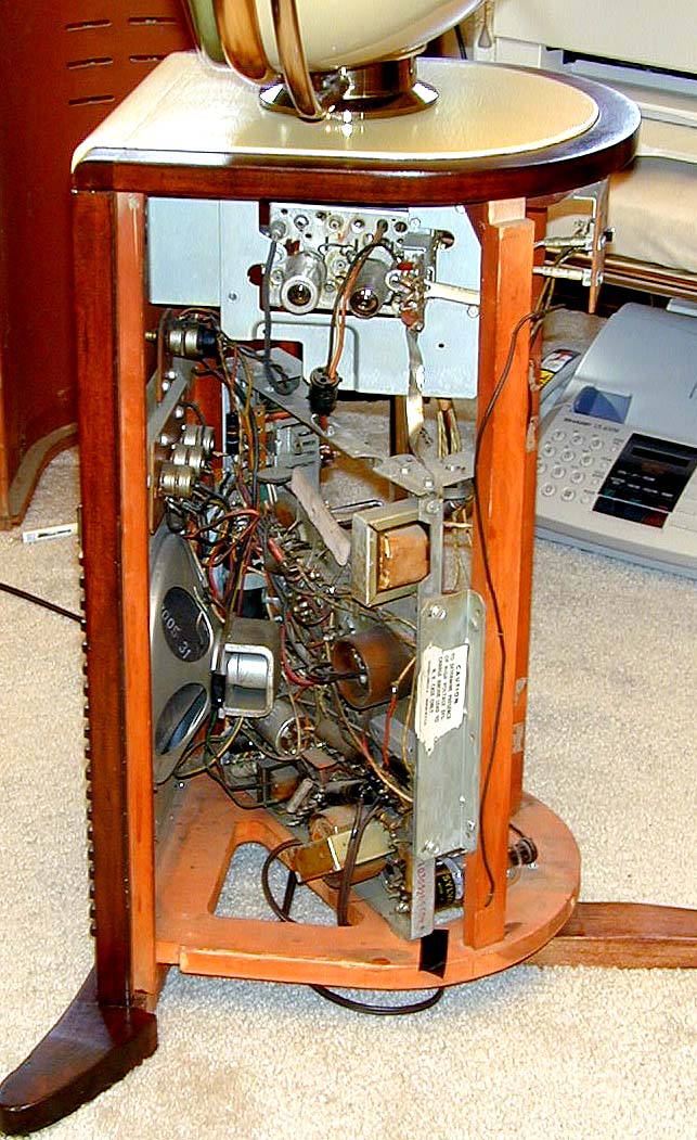
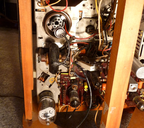
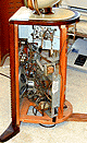
The designers turned the chassis sideways to fit the slim upright cabinet. Here's
a view from the left side after I had removed the curved rear cover.
The main chassis sits diagonally, occupying the lower
two thirds of the cabinet. Above it is the separate tuner chassis, connected
by two cables and a ground strap.
The previous owner replaced a broken rear cabinet foot with
a nice mahogany reproduction. After I finish the electronics, I may shoot the repro foot
with a little toning lacquer to better match the cabinet color.
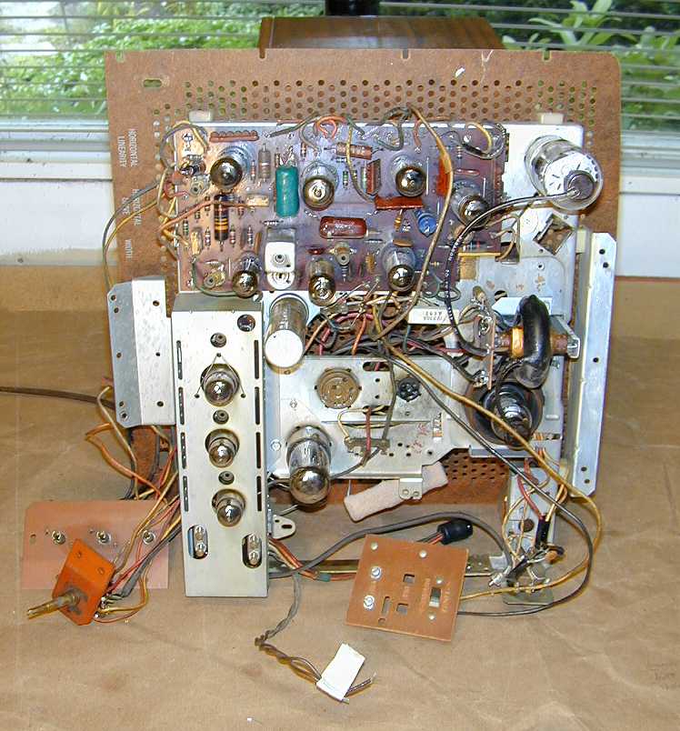
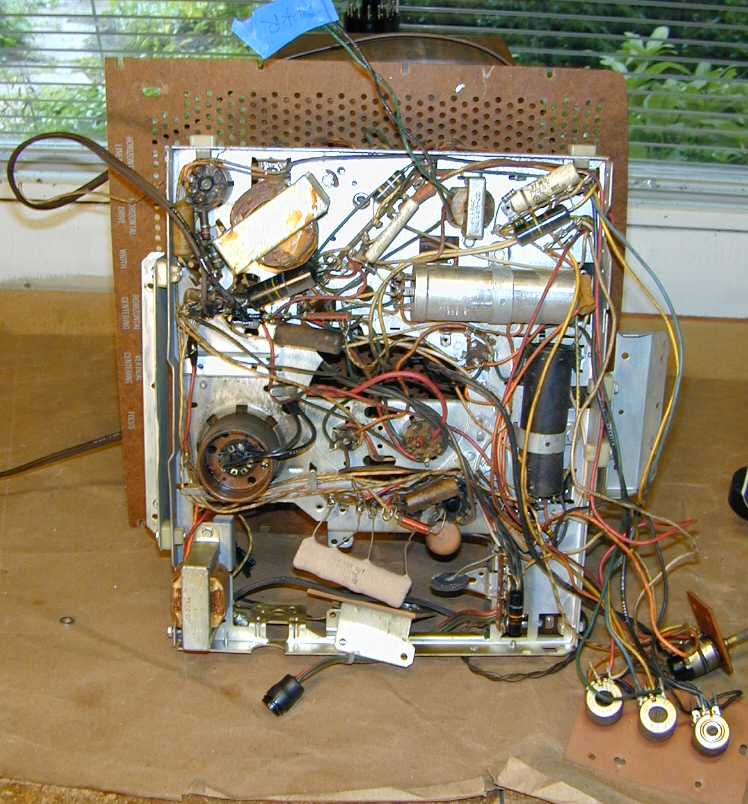
Below is a view of the chassis from the right side. All of the tubes can be reached from here,
and the open layout lets you do simple repairs without removing the chassis.
Notice the thick
bunch of cables connecting the main chassis to the CRT above. The dark rectangle
at the bottom, thickly crowded with components, is the infamous PC
board, which I would come to know intimately later in this project.
Initial inspection of the chassis revealed no major horrors, although
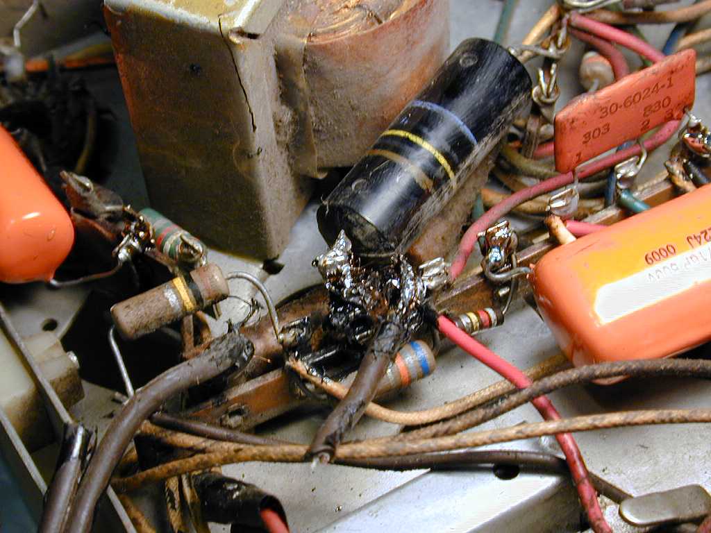
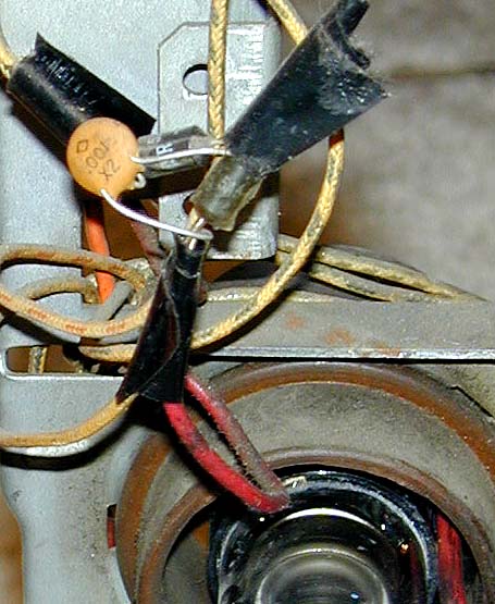
some spots showed rather sloppy repair. Check out this photo.

A previous serviceman—perhaps
the one who "made it work" just before sale—replaced the rectifier diodes and
left them hanging in midair, along with the little capacitor,
insulated with a couple of licks of electrical tape.
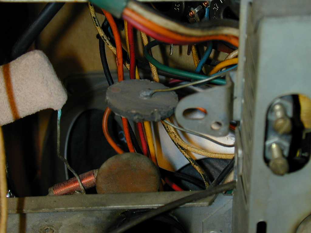
Another ugly spot was the connection of the AC line cord to the chassis. This photo
shows the area when I had started to remove one leg of the cord.
The repairman covered the sloppy solder joint with sticky black
"liquid tape." The cord was installed without any strain relief,
causing the joint to break the supporting terminal board when the
cord was yanked. I will have to clean up this mess,
repairing the broken terminal board with epoxy and adding a strain
relief mounted to the chassis to avoid future damage.
The Predicta contains some components that you won't see in earlier TVs.
The previous photo shows one of the "couplates." It's the
flat orange component with three terminals labeled 1-2-3. These are
early integrated circuits, combining resistors and capacitors in a single
package. Later in this article, you'll see how I built a substitute.
The next photo shows a "thermistor," also known as a surgistor
or inrush limiter. It's the black, pancake-shaped component with two leads
near the center of the photo.

A thermistor, or thermal resistor, is one whose resistance changes as it warms
up. The Predicta specs call for this unit to have 400 ohms resistance when cold
and 11 ohms when hot. It is installed between the AC line and the TV's string of tube
filaments. This softens, the initial rush of current flowing to the tube filaments,
helping to extend tube life.
Having a thermistor in the filament string makes the TV slow to warm up.
A Predicta typically takes about a minute to start playing.
If a thermistor fails, the TV gets no power at all. That was the case with
my RCA CTC-11A color "roundie."
As I learned with that set, replacing a fried thermistor with a new CL-90
costs about $1 and takes only a few minutes.
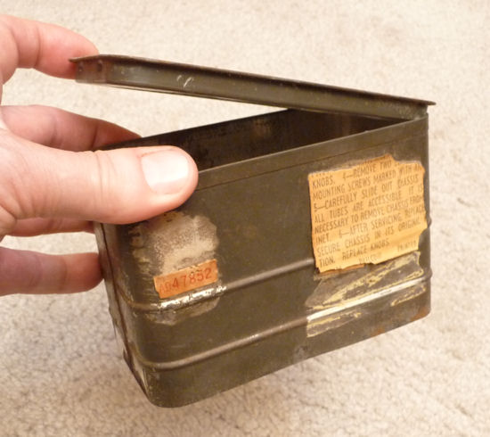
My Predicta was also missing the metal cage that encloses its high-voltage rectifier
tube and flyback transformer.
Although not strictly necessary for operation, the H-V cage keeps
fingers away from shocks. Near the end of this article, you'll learn
how I found one.
Restoration
If you are new to TV restoration, I have some friendly advice for you: avoid the Predicta.
At the time I tackled this restoration, I had already done several tube TVs. I
found this job tricky and occasionally unpleasant by comparison.
The Predicta has some very finicky spots, notably the main PC board, and it
has a transformerless AC/DC power supply, which increases the hazards of working
on a TV chassis when powered up.
The Predicta also had a poor reliability record, meaning that you may have
to cure a bevy of problems—not only one—before you get a working TV. If you get a
non-working Predicta, follow the Boy Scout motto and Be Prepared!
While this story had an eventual happy ending, there is no way that I would
recommend a Predicta to a beginner. Before you tackle one
this, find an inexpensive (and simpler) 1950s tube TV to practice on.
I was greatly assisted in this project by
experts from the rec.antiques.radio+phono
USENET newsgroup. Without their answers to my questions, I might
never have finished the restoration.
The discussions from rec.antiques.radio+phono members included all sorts of
useful Predicta lore, tips, and tricks. I have placed this
lengthy material at the end of this article. It is well worth reading
before you start any Predicta project.
Electronics
The Predicta is a fourteen-tube television. It is newer than most of my
other tube TVs and it uses a tube lineup that was rather new to me at the
time.
| Tube |
Type |
Function |
| V1 |
3BZ6 |
1st video IF amplifier |
| V2 |
3BZ6 |
2nd video IF amplifier |
| V3 |
5AM8 |
3rd video IF amp/Video det. |
| V4 |
6AW8A |
Video output/Noise inverter |
| V5 |
3AU6 |
Sound IF amplifier |
| V6 |
3BN6 |
Audio detector |
| V7 |
12CA5 |
Audio output |
| V8 |
9BR7 |
Sync. sep/Horiz. AFC |
| V9 |
10DE7 |
Vert. mult./Vert. output |
| V10 |
6CG7 |
Horiz. multiplier |
| V11 |
12DQ6A |
Horizontal output |
| V12 |
12D4GT |
Damper |
| V13 |
1B3GT/1G3GT |
Horizontal rectifier |
| V14 |
21EAP4 |
Picture tube |
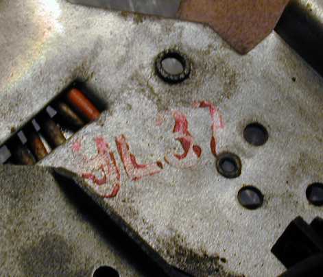
Philco made several flavors of Predicta and there were changes for
various production runs. It's vital to have the right service
manual. Mine has chassis type 9L37, as indicated by the red stamp.
The Sams Photofact for this model is
Set 439, Folder 1, dated 4-59. When I
restored my second Predicta (which uses a different chassis), I discovered an
original Philco factory manual for it. I recommend using both manuals if
you can obtain them. This article refers to components by their Sams parts numbers.
The first step, as always, was to clean gunk from the chassis. Mine was incredibly dirty. Every inch,
every component, was coated with a thick layer of sticky, gummy goo, covered
by dust. Perhaps the previous owner cooked a lot of greasy food in a house with
poor ventilation. I carefully cleaned everything with rubbing alcohol, a soft toothbrush,
Q-tip swabs, and soft rags.
Inch-by-inch cleaning offers an opportunity to inspect the chassis for damage
or bungled repairs. Among other things, I discovered that one filament lead for
the high-voltage rectifier tube was not soldered to its terminal. The
lead was crimped onto the terminal, but apparently had never been soldered!
I also found a couple of "cold" solder joints that had never adhered properly.
Although the lead happened to be resting close enough to the terminal to make
an electrical connection, the slightest jar might separate it, causing
the TV to misbehave if someone stomped past in the room.
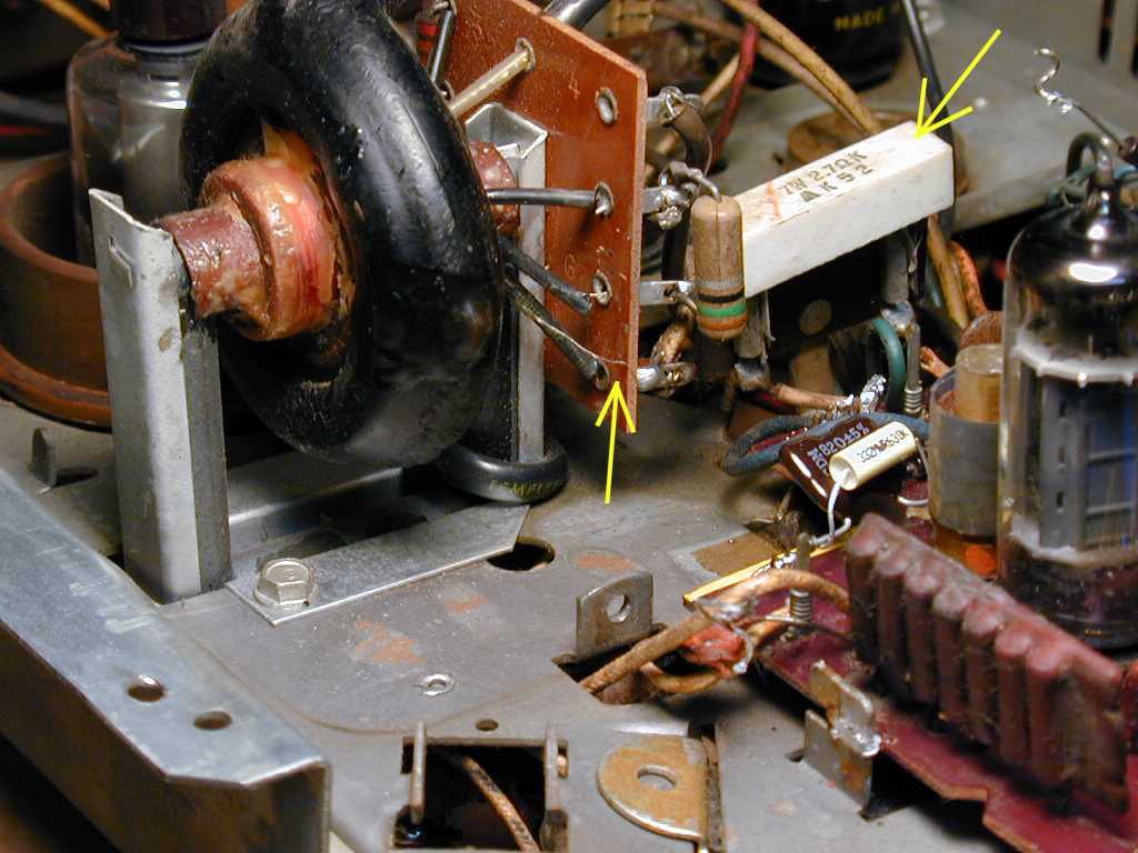
While cleaning gunk off the flyback transformer, I managed to snap
a hair-thin lead, which is marked with the central yellow arrow in the next photo.
I succeeded in reattaching the wire, but it was a real pain. This kind of wire
practically vaporizes in front of your eyes if you apply too much heat.
Be careful around your flyback transformer. If you can find a replacement,
it will be expensive.
The previous photo shows
a second point of interest, marked with another yellow arrow at upper right.
In my set, the white component was a 7-watt 2.7-ohm power resistor—the
wrong component! This Predicta uses a 7-watt 5.6-ohm fusible resistor ("fusistor")
in that spot. Old-style fusistors are not readily available, so I would replace it
with a resistor of the correct value, in series with a fuse to protect the TV's
B+ circuits.
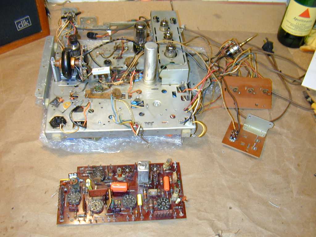
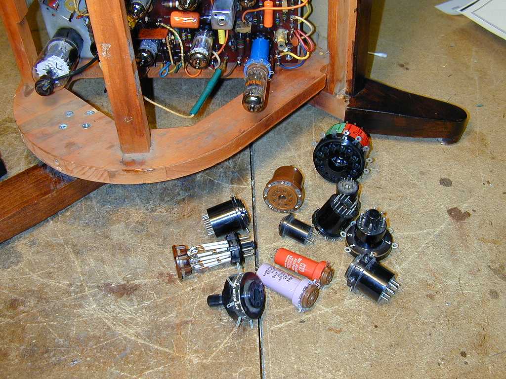
Removing the Chassis
The main chassis is connected to other things with various cables and leads.
Before removing it, make some notes (or even take photos) to guide you in reassembly.
After disconnecting the plugs and leads from the main chassis to other chassis, you can
loosen two boards that hold the front controls and the rear antenna terminals. Each of them
is held on with two wood screws. It's simpler to
keep these little boards connected to the main chassis while you work on it, although you need
to use care to avoid breaking connections while working on the chassis.
You also need to disconnect two leads to the speaker. In my case, that meant unsoldering two
wires at the speaker. As we'll see in a moment, it normally means removing two
wires from the PC board.
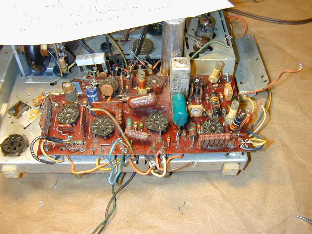
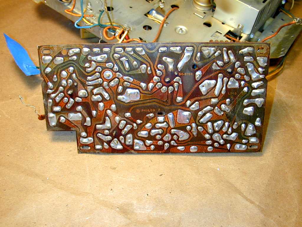
The next photos show the chassis on my workbench. In the first view, the main PC board is at the top.

In the second, under-chassis view, notice how the chassis permits no access to the bottom
of the main PC board. That board must be removed in order to rebuild it.
Removing the Main PC Board
The main PC board is connected to the chassis with six solder lugs and over two
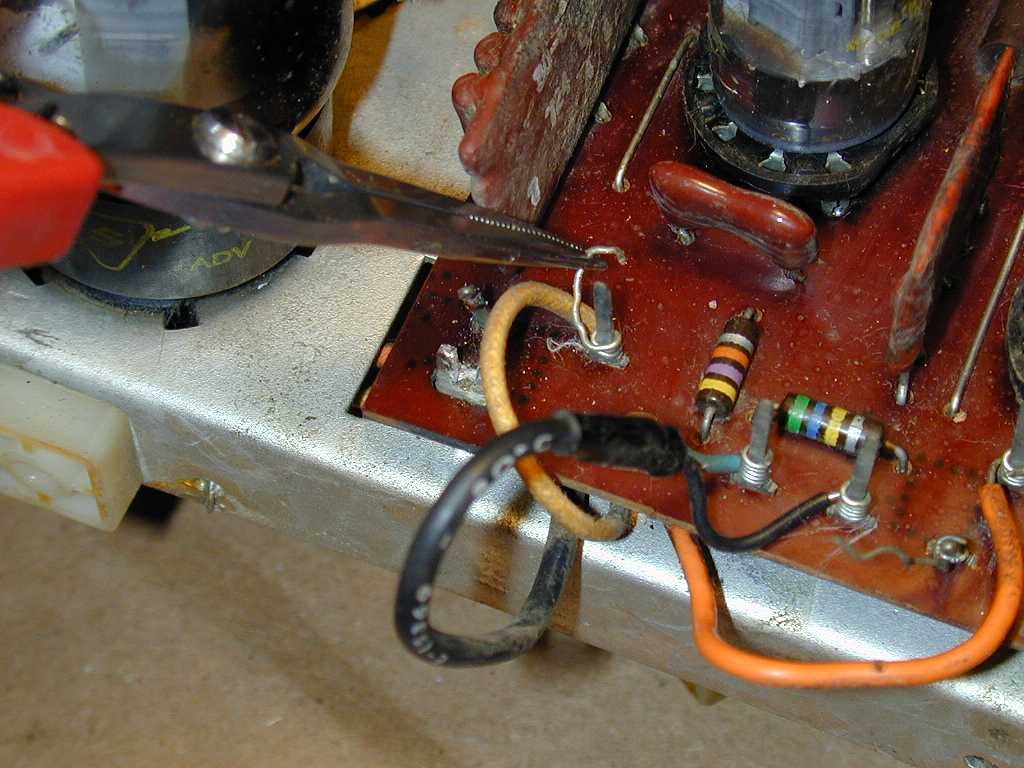
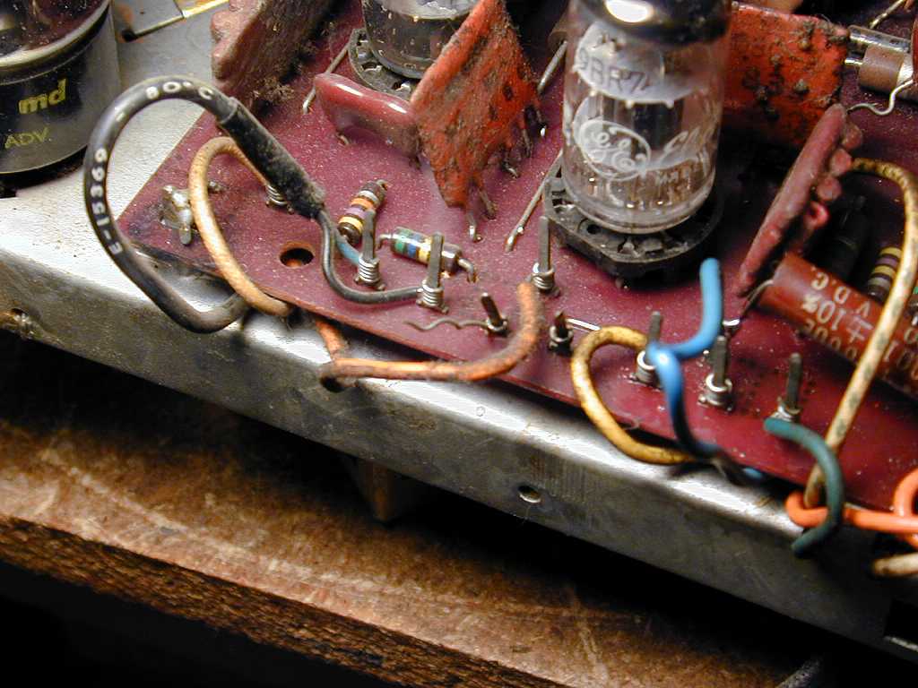
dozen wire-wrapped connections. The next photo shows one corner of the board, with
connecting leads still attached.

Near the center of the photo, you can see two wire-wrap pins connected to nothing. One still
holds the remains of a wrapped lead. These leads puzzled me at first. The TV worked
normally, but something had been disconnected.
I later learned that these are attachment points for the speaker wires. A previous
repairman had rerouted the wires and made a direct connection between the audio output
transformer and the speaker.
The previous photo also shows some of the multi-component "couplates" used in this PC board.
On three sides of the 9BR7 tube you will see flat, orange components. The rightmost one looks like a wafer with
four cylindrical shapes on its side. I will later replace this one to fix the vertical
hold.
At the lower left corner of the board, partially hidden by a yellow lead, you can see one
of the six solder lugs that connect the board to the chassis. These must be carefully
unsoldered and loosened to remove the board. There is one lug in each corner of the board,
a fifth near the center, and a sixth at the left side, to which a small ceramic disc
capacitor is attached.
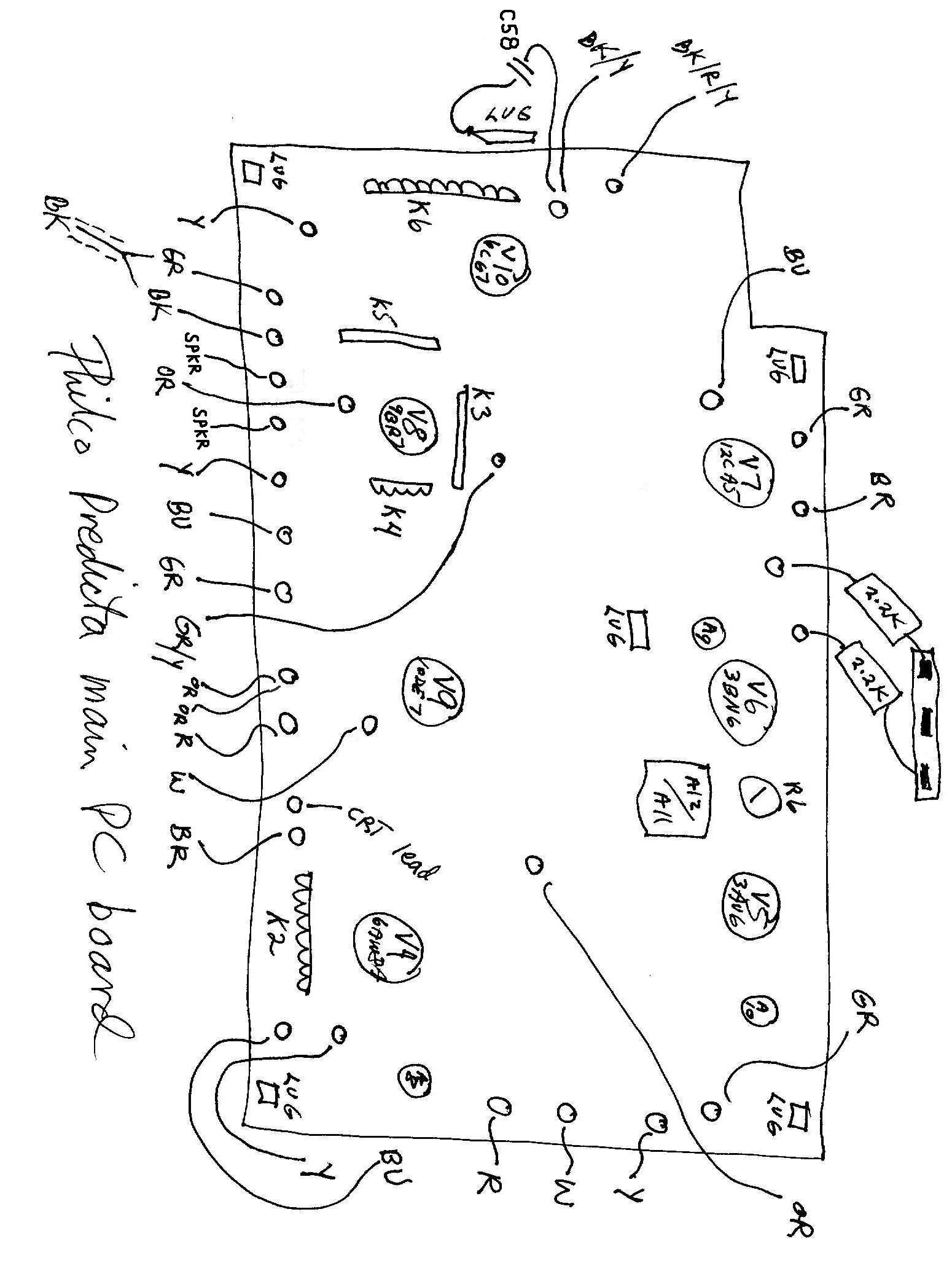
Before disconnecting anything, I made a drawing of the board that showed every connection
and lug. This would serve as my roadmap back to Kansas, and I strongly recommend that you
use such a diagram rather than rely on your memory.
Below is my hand-drawn diagram. If you have the Sams Photofact, you can save time by
annotating page 17 with the same information. This diagram applies only to my model.
I assume that the board for the 17-inch sets will have some differences. You may also notice
some differences in wire colors, so make a careful note of what is present in your set.
2012 update: When I restored my second
Predicta, I got a copy of the Philco factory service manual, which includes a
diagram showing all of the board connection information. I recommend getting a
copy of the Philco manual if possible.
The next photo shows how I began to disconnect the board.
The photo shows how I gently unwrapped each lead from its pin, using a thin needlenose pliers.
Take your time and avoid breaking the brittle wires. You may find that some leads have been
soldered in place during past repairs. These can still be unwrapped if you suck away excess
solder and heat the pin while unwrapping.
The ground lug in the corner has already been freed. I first heated the connection with
a soldering iron and used a solder sucker to remove as much solder as possible. Then I
reheated the connection and carefully bent upward the little flat pin that folds over into a
slot in the lug. Be careful not to break these pins!
They form electrical ground connections in the PC board circuits, as well as making a mechanical
bond. If you break off a pin, you will need to restore the ground connection.
Now the PC board has been completely disconnected. It is ready to be lifted from the chassis.
The photo shows six tubular capacitors that I will replace. Four of them are colored
blue or tan. Two of them have colored stripes. You can read about general
capacitor replacement elsewhere in this website.
Before replacing any components, I spent a long time cleaning sticky dirt off the board, using rubbing
alcohol and dozens of Q-tips. I cleaned both sides of the board, carefully inspecting the underside
for any cracks or cold solder joints. Here is a view of the board's bottom.

Replacing Components on the PC Board
With the board out, I started replacing capacitors one by one. A few
had previously been replaced, but I redid them, anyway, not knowing the
quality of the replacements or how old they might be. Besides, the work was sloppy. Instead
of removing the board, the repairman had snipped the leads from above and tack-soldered new
leads onto the stubs. I also redid a few resistors that had been sloppily replaced.
For PC board work, use a small soldering iron, not a heavy soldering gun. Too much
heat can damage the delicate foil that forms connections under the board.
To remove a component from the board, I first snipped its leads from above. Next, I used
the iron and a solder sucker to remove excess solder from the connection point on the opposite
side of the board. Then I reheated the connection and gently removed the old wire stub by pushing
from above.
Don't use too much force when pushing out old leads, or you may tear loose the foil,
breaking the connection and making more work for yourself. If your board has a
broken trace, or if you happen to damage the foil by accident, it can be repaired by
soldering a fine piece of wire to bridge the gap. You may need to delicately scrape
the foil to bare metal to get solder to stick.
Coached by some experts in the rec.antiques.radio+phono newsgroup, I knew in advance
that one of the couplates on the PC board was a common trouble spot and should be replaced.
This component is labeled K4 in the Sams literature.
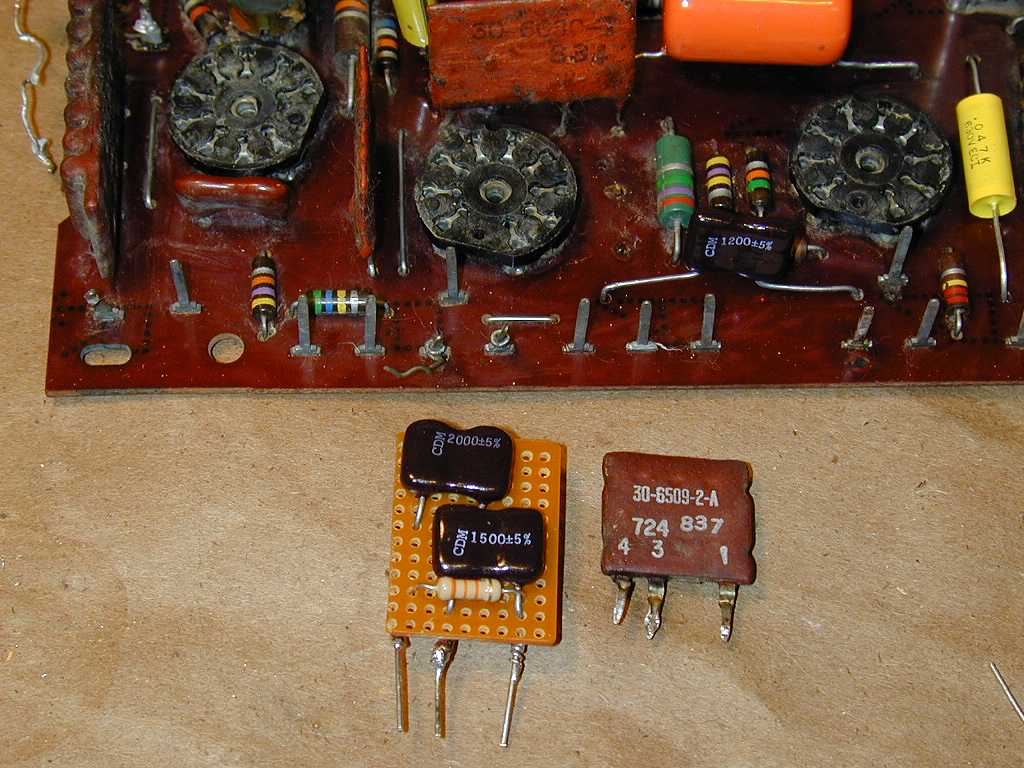
The next photo shows the old K4 couplate next to my replacement.
To the right of the middle tube socket, you can see three empty holes
in the PC board where the old couplate was installed. The photo also shows
some of the newly replaced capacitors.
The K4 couplate contains four components: two capacitors and two resistors. (The Sams schematic
shows these components rather confusingly inside two separate
dotted-line boxes.) My replacement was made of perf-board with components on both sides of the board.
One of the capacitors is 2200 pf in
value. The 2000-pf capacitor shown in the photo was paralleled by a pair of 100-pf capacitors
on the opposite side, to achieve the correct value.
Component values are critical in this part of the TV, so your replacements
must have exactly the same values as the originals. The capacitors should
be rated at 1000 volts, the same as capacitor C38 on the board.
You can read more about couplates in the newsgroup notes at the end of this article.
We're Almost Done!
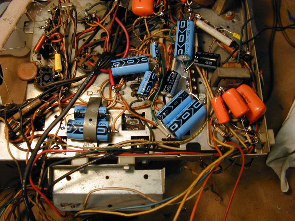
The board was finished, but I wasn't done restoring this set. The Predicta uses eight electrolytic
capacitors, which I replaced by disconnecting the old can units and wiring new replacements
under the chassis. I added a small terminal board to anchor some of them. In a couple
of cases, I wired two caps in parallel to get a capacitance value that I didn't
have on hand at the time.
If you replace capacitors under the chassis, pay attention to their position.
The back of the speaker frame protrudes into this area when the chassis is installed.
You don't want to cause any short circuits or put undue stress on things.
At last, we are finished rebuilding the PC board and recapping the rest of the chassis. Now
it's time to get out that diagram and reconnect everything.
I didn't try to re-wrap the old leads. Instead, I first removed all old solder
from the board's pins and cleaned them using a Dremel Moto-Tool and a small metal brush.
Then I wrapped each lead about twice around its pin and soldered it on. All of the lugs
were resoldered, as well as the two resistors and the single capacitor that hangs off the board.
Checking my notes and pre-restoration photos, I reinstalled everything in the cabinet.
Just when I thought I was done, I noticed that one of the leads to a front control
had snapped off its terminal. No doubt this happened in the course of turning the chassis over
on the bench. After resoldering that lead, I crossed my fingers and powered up the TV for
the first time in a long while.
The results were mixed. The TV had a strong, bright
raster, but the picture was washed out and both horizontal and vertical sync
were lost. The sound was excellent, but the volume was at full blast, unaffected
by the volume control.
The audio problem was easy to fix. Looking closely at the volume control, I saw that
its lead had cracked loose from handling, although it was hanging close enough to
escape previous inspection. When it was resoldered, the sound returned to normal.
The video problems took more time. Preliminary checks didn't reveal anything obviously
amiss, such as tubes in the wrong sockets. I started checking voltages on the PC board
tubes, starting with V4, the 6AW8A video output/noise inverter tube.
How, you might ask, do you test voltages on a tube whose socket is hidden under the
bottom of a PC board? The answer is to use a tube extender, which exposes the tube pins
above the chassis. The next photo shows the 6AW8A tube plugged into a blue extender
on the bottom right of the PC board. Extenders for other tube types are also shown
on the workbench, including a homebrew extender that I made years ago when restoring
my Hallicrafters SX-28 communications receiver.

The voltage check showed almost no voltage on
either of the 6AW8A tube's plates, where high voltage is expected.
Asking the rec.antiques.radio+phono newsgroup for advice, I got this
prescient reply from Bonita Geniac.
The problem seems to be very low B+ feeding to the 6AW8. The brown lead
next to K2 indicated as #19 on Sams page 17 seems to feed from the R33
3900 7 watt under the chassis. The other end of that connects to the 280
B+ source and to R36, a 330K going to the brightness control. We know
you have 280 B+ somewhere in the set because the Horiz sweep and vert
sweep both feed off it and are working. My best guess is that you have
accidentally misconnected the brown wire which belongs on pin #19. There
is a terminal right next to #19 on the board which the cathode lead from
the CRT plugs onto called #20 on Sams page 17, it would be between the
#19 terminal closest to K2 and the one with the red wire on it which is
#21. If you reversed those two, the B+ would not be connected to the
plate circuit of the 6AW8, and the video signal/brightness control wiper
would not be connected to the CRT cathode, giving exactly the symptoms
you describe. When you look at the board, the brown wire goes to the
1.5K 2W resistor, and the lead from the CRT goes to the .047 cap. Of
course,a broken connection or short anywhere in the vicinity of the R33
3900 7 watt resistor or a problem with the board itself could still
exist. Measure the voltages at both ends of R33 and see what happens.
Sure enough, the leads had been reversed, despite my precautions. When I drew
the PC board diagram days earlier, I had left out the pin to which the lead
from the CRT cathode is attached with a slip-on connector. I guess I was
concentrating too hard on the wirewrapped connectors when I drew the picture!
Five minutes later, the mistake was corrected and the
TV played like a champ.
If you look back at the previous photo, you will see the CRT cathode lead connected
in the correct place. It is a yellow lead with green insulation near the end,
located to the left of the 6AW8A tube on its blue extender. (The hand-drawn diagram which appeared earlier
in this article has been corrected to show this lead in the right position.)
Closing Thoughts
My Predicta logged many hours after I finished the basic restoration.
It is a very watchable television, with excellent brightness and sharpness.
It's also sensitive, easily pulling in weaker stations that are hard
to receive on some of my other restored TVs.
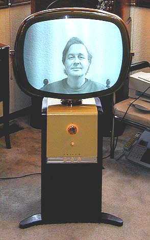
The next photo shows a live broadcast, received using a rabbit-ear antenna in my workshop.
Movie 1
You can click on the Movie 1 link next to the photo to view a short MPG movie clip
of the same material. (If you are using a slow connection, you can save
a local copy of the file and play it from your computer, rather than listen to
the movie stop and start as it downloads. In Windows, simply right-click
on the Movie link and then choose Save Target As...)
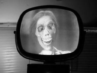
And just for fun, what better use for a vintage TV than to watch vintage movies?
The following clip is from Alfred Hitchcock's Psycho.
Movie 2
The actual picture quality is much better than what you see in these movie clips. To avoid
making the MPG files too large to download, I saved them in a low-fidelity format.
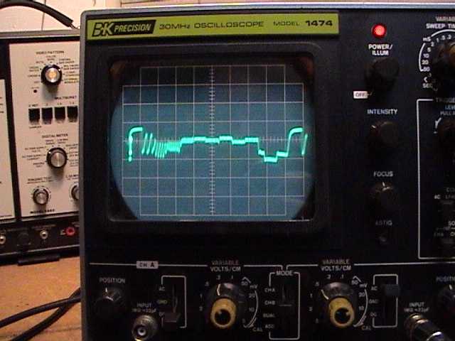
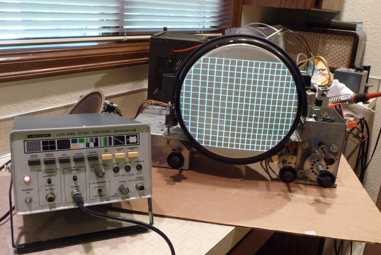
Just as I was completing the project, I bought a Sencore VA62 Video Analyzer, which
can be used for TV alignment among other tasks. In the next photo, the VA62 is partially
visible in the background.
In the foreground is my oscilloscope, displaying a test
pattern piped into the TV from the Sencore instrument. I can't claim to be an expert
in using this complicated TV analyzer, but I did manage to sharpen up the alignment
and achieve very precise settings for the vertical and horizontal centering and linearity.
This project was a real adventure in learning. I never could have accomplished it so
quickly without all the great information from the rec.antiques.radio+phono newsgroup,
especially Bonita Geniac.
Once the electronics were working well, I brought the Predicta into my
office, where I watched it regularly for several years.
2009 Relapse
Eventually, my Predicta was pushed off to the side and seldom used.
These things happen when you keep getting new TVs! I turned it on one day,
after a long period of disuse, and noticed a problem.
After playing for a while, the vertical became twitchy and then
started rolling. Before long, the horizontal went out, too.
Time for a tuneup. I brought the set into the workshop and checked the
tubes, all of which tested strong. Reinstalling them, I was dismayed to see
even worse problems. The audio was gone, and the picture was extremely
washed out, almost negative.
Naturally, I checked to make sure I hadn't put a tube in the wrong socket
or knocked something loose while moving the set. If only life were so simple!
A quick oldtimer's check of the audio section is to touch the tip of a
powered soldering iron to the middle contact of the volume control. A
buzz (which I heard) indicates that the amplification section is working.
I also got a tone when injecting an audio signal (at test points 25 and 26
in the Sams schematic), confirming that the amplifier part of the sound
section worked OK.
Since the problem affected both sound and picture, I guessed that
it was located somewhere at or before the point where the audio signal
is separated from the video. In the Predicta, this "sound takeoff"
point is at the 6AW8A tube.
I began checking voltages and resistances against the
charts in the schematic. The voltages were too high at the 6AW8A tube,
and also incorrect at other tubes, such as the 3AU6 audio IF amplifier.
Some of their resistance values were wrong, too.
Not seeing an obvious cause, I called for help from the TV forum
at antiqueradios.com.
One of the members suggested that my 6AW8A tube was gassy. The tube looked fine on my emission
tester, but that tester can't check for gas. I borrowed a known-good 6AW8A from
my CTC-11A television. The video came back, confirming that the old tube had problems.
The audio was still silent, however. I decided it was time to pull the PC board and
get serious. Who knows, perhaps the board had a broken trace somewhere, or a cold
solder joint that prevented one of the board grounds from working completely.
Removing the board went more quickly the second time around, but it's still not
my idea of fun. I settled down with the schematic and parts list
and began the process of testing all 29 resistors. It didn't take long to find
problems. One resistor was completely open. Another had drifted upward in value
from 820K to 3.8 megohms. Several others had drifted beyond an acceptable tolerance.
Here's the board partway through the replacement process. I also replaced the little
capacitor that hangs off the left side of the board and connects to a ground lug.
The tiny original (C58) was a ceramic. It tested OK, but its body was starting to
crumble around the leads. I replaced it with a 1000pf mica cap, as seen here.

I had no way to directly test the original couplates remaining on the board,
nor did I have on hand the components that would be needed to build substitutes.
Old Predicta hands had told me that those couplates were not known as frequent
troublemakers, so I replaced the remaining bad resistors and reinstalled the board.
Victory!
The new resistors brought back the audio and now the picture looks
fantastic. There is no trace of the vertical and horizontal
instability that prompted this trip to the workshop in the first place.
If I ever restore another Predicta, I'll take the time to test all of
the resistors on the PC board. That couldn't have prevented a tube from
going gassy, but I might have avoided having to pull the board a
second time.
The ground connections on this board can be troublesome. Different
parts of the board make separate connections to chassis ground via the lugs.
If one of them has a bad solder joint, you have trouble. It's not
a bad idea to make a new lead that connects all of the board's grounds.
Then, the board needs only one solid connection to ground for
all of them to work correctly. This emulates newer boards,
in which a ground bus runs all the way around the board's edge.
Final Picture Adjustments
Before putting the Predicta back in my office, I hooked up
a pattern generator to check its screen geometry. Touching up
the vertical height, centering, and linearity took only a few minutes.
The horizontal adjustments were more troublesome. Both centering
and linearity were slightly off. You wouldn't notice the issues
in normal viewing (see the photo of Dorothy above), but I wanted
to make them as good as possible.
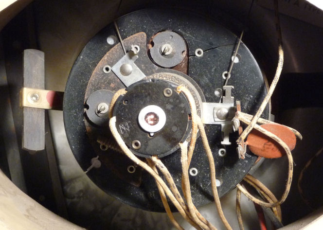
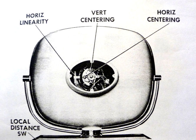
These photos show two of the horizontal
adjusters, located behind the picture tube.


The centering adjusters are circular magnets which you rotate. The
linearity adjuster is a long, flat magnet on a bendable metal arm,
held to the left of the picture tube yoke.
Rotating the horizontal centering magnet seemed to work at first,
but as I kept turning, it reached a maximum point and then started
moving back in the other direction.
I moved on to linearity, which controls whether one side of the screen
is "squished" compared to the other. As you might imagine,
if the left half of the screen is stretched out too far, compressing
it to match the right side will also move the center point. The
linearity and centering adjustments are interactive, in other words.
Perhaps correcting linearity would also cure the slight centering problem.
It wasn't immediately obvious what to do with the linearity adjuster, and the
service manual gave no details. Are you supposed to rotate it?
Slide it left or right? Twist its ears? Bend it forward or back?
Other Predicta owners advised that you're supposed to bend the
adjuster arm, even though that seems like a dodgy arrangement.
Bending it straight forward or back was the answer. (Twisting it so that one ear moves
forward of another simply deforms the vertical linearity on the right side of the screen.)
Just as with the other adjuster, I could only do so much with this one.
Perhaps the magnets have weakened with age, something I've also found
with convergence magnets in old color TVs. In any case, I eventually reached
the best compromise available with these adjusters, and called the job done.
Other Predicta owners tell me that it's a rare 21-inch set which doesn't
have some slight defect in screen geometry. That's true of most
vintage TVs, in fact. Fortunately, if you spend your time watching movies
and shows rather than test patterns, these minor technical nits won't
matter.
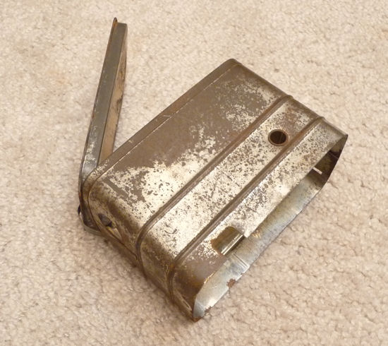
Finding a High Voltage Cage
About ten years after I first posted this article, a fellow
collector donated a high voltage cage from a parts chassis.
I had given up trying to find one, so this was a welcome surprise.
The cage has a pop top, hinged with a little spring on one end.
It has two holes, one on the side for the red high-voltage lead to the
picture tube, and the other on the end for the black lead to the
12DQ6A horizontal output tube. A rectangular opening on the side
makes room for wires to the flyback transformer.


The cage appears to be plated with tin, like an old fashioned sardine
can. I removed some surface rust with Naval Jelly, but didn't
worry about trying to make it look perfect. This is a working
television, not a museum piece with innards on display.
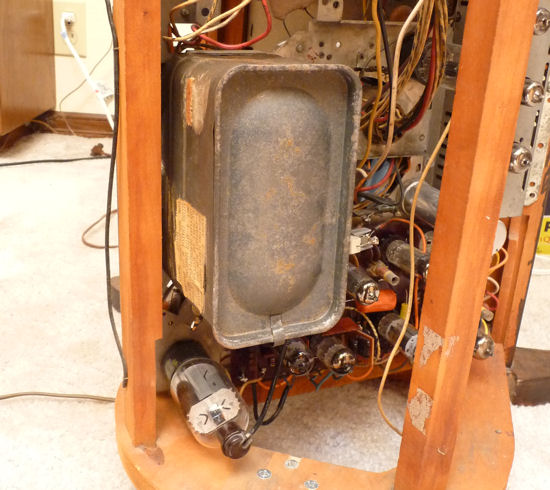
This photo shows where the cage will go. I have removed the
1B3GT high voltage rectifier tube so that you can see where the
red CRT anode lead goes. In this view, its end plugs into
a little hole to the right of the tube socket. The black lead to the
horizontal output tube comes from the board on the flyback
transformer and has been unplugged from the tube cap in this
view. The cage will enclose the 1B3GT tube and the flyback,
the black doughnut-shaped object in the middle of the photo.

To install the cage, I disconnected both leads and sent them through
the holes. The cage has two little slots at the top (in this view)
that fit two tabs on the chassis. At the bottom is a hole for a
mounting screw.

All done. The TV is safer to operate with the cage in place, and
it's great to have a complete set after all these
years. Thanks, Tim!
Newsgroup Notes on Predicta Repair
Below are edited discussions on Predicta topics from the rec.antiques.radio+phono
newsgroup. More discussions can be found by searching the newsgroup archives at
Google.
Search for "Predicta" and you'll learn a lot.
From: Phil Nelson
Subject: weak points of Predicta TVs?

During the next month or two, I'll get a chance to start on my Predicta TV.
It already plays reasonably well, so my main objective will be to
"do no harm" while recapping and making it reliable.

Just wondering if there are any notorious weak points that deserve special
attention.

Thanks!

Phil Nelson


From: Bill Sheppard
Subject: Re: weak points of Predicta TVs?

Phil, here's some good Predicta sites & links -

http://www.telusplanet.net/public/napp/philco.htm
http://members.aol.com/thefiftys/html/predicta.htm
http://www.gregssandbox.com/gtech/predicta/

A little factoid: On the model with the 'totable' CRT head, they had to
redesign the video out stage with a cathode follower to drive the long
coax cable that carried the video. The cable's extra capacitance
would've smeared the signal. The K follower's low impedance overcomes
that problem.

oc


From: George B. Shields, Jr.
Subject: Re: weak points of Predicta TVs?

The console models are electronically identical to the Holiday Predicta
tabletop only, and not the 17" metal version.  The 17" version was actually
the best electronically.  The others had transformerless chassis which ran
much hotter than the transformer models, which leads me to the main
weaknesses of the console versions.  The added heat helped cause the early
printed circuit boards to warp and fail in time.  Furthermore, you will most
likely find the vertical integrators are weak and will need to be rebuilt
(replaced).  You cannot find replacement vertical integrators, so you'll
have to rebuild it with external  components (capacators and a diode).
Beyond that, if it still works well, consider yourself fortunate and enjoy!

-George-


From: Bonita Lee Geniac
Subject: Re: weak points of Predicta TVs?

Well, the 17" is by far the better of the two sets electrically, but
neither one is very good. It had been widely publicized that the
Predicta was what caused the failure of Philco and its sale to Ford a
couple of years later, supposedly they had over a 100% in warranty
failure rate on those sets especially the 21" model.

If you like to cut corners, its easy to recap from the top side of the
PC board, but they usually have bad tube sockets, loose solder
connections, or other problems along with the caps. In order to get to
the foil side of the board to do any soldering, you have to remove about
25 wire/wrap connections from stakes on top of the board then unsolder
quite a few mounting points from the chassis, and completely remove the
board from the chassis. Some genius decided they could have basically a
solid metal chassis below the board.....didnt think the set would ever
need any service. Otherwise the only thing you can do is crush the old
part or clip the leads right next to it and solder the new part to the
stubs of wire left on top of the PC board. I have a wiring chart made up
showing which color wires go where because I almost always remove the
board, replace everything known to fail, then reinstall it.

The flybacks are famous for overheating and melting all the tar off
them, and are scarcer than hen's teeth and new ones are about $200 if
you can find one and the seller knows what it is for. But at least they
will work halfway decent after everything is done.


From: Ed Ellers
Subject: Re: weak points of Predicta TVs?

The irony here is that Philco was known for some years for its "Cool
Chassis" design (in conventional B&W TVs) that was supposed to address that
problem.


From: Ken G.
Subject: Re: weak points of Predicta TVs?

I restored a Holiday model years ago that was all original. one big
problem was the old bypass caps on the circuit board.
I replaced them with exact values but had to go back & change a couple.
slight value changes made a world of difference in the vertical size. I
also had a schematic because mine had those striped ones.
I would make a paper chart and lay those old caps out in there original
places so you can go back & check things. I got mine fine tuned with my
cap sub box. it worked just fine after that.

I got the chance to look inside and estimate repairs for a dealer here
in town on a set like yours. it had the same chassis standing on end
sorta at an angle with the tuner mounted different.

ken


From: Phil Nelson
Subject: Re: weak points of Predicta TVs?

> Furthermore, you will most
> likely find the vertical integrators are weak and will need to be rebuilt
> (replaced).  You cannot find replacement vertical integrators, so you'll
> have to rebuild it with external  components (capacators and a diode).

I'm feeling a little stupid here. I found the vertical integrator in the
Photofact. It is K3, apparently an integrated circuit with a little array of
capacitors and resistors in a flat case.

Most of the innards of K3 are straightfoward, but I'm not sure what to do
with the two components next to lead #3. The resistor is labeled 90K and the
other component is 4000mmf. (Is the 4000mmf component a capacitor wired in
parallel with the 90K resistor?) If this is where I'd use a diode, can you
explain what value of diode to use and how it would be connected?

Thanks!

Phil


From: Bill Sheppard
Subject: Re: weak points of Predicta TVs?

Phil, are you intending to build a replacement for that vert.
integrator? If so, that 90K resistor should have two .002 caps, one from
each end to ground (.002 being half of 4000 pf.). At least that's the
way we always did it, and it worked fine. No diode is involved.

Those encapsulated multi-component doohinkys were called
'couplates', BTW.  There's another 'tiered' version of a couplate that
looks like a Borg ship. It goes by another name, which escapes my
memory. No doubt someone knows it.

oc


From: Phil Nelson
Subject: Re: weak points of Predicta TVs?

Thanks for the tip. I'm not eager to rebuild that component, but since it
was mentioned as a weak spot, it's nice to know what to do, if needed.

My plan is to do a basic recap and then see where things stand. At this
point, the TV plays pretty well, the most noticeable symptoms being some
vertical instability and taking a l-o-n-g time to warm up. The power supply
(even the pilot lamp) also seems to flicker occasionally during warmup; that
may be cured when I improve some of the previous serviceman's friction tape
work.

Phil


From: Troglodite
Subject: Re: weak points of Predicta TVs?

>BTW.  There's another 'tiered' version of a couplate that
>looks like a Borg ship. It goes by another name, which escapes my
>memory. No doubt someone know

Those were called "cordwood modules." (Presumably after the way firewood
is stacked.)

Doug Moore


From: Bill Sheppard
Subject: Re: weak points of Predicta TVs?

I don't know if this is true of all Predicta models, but on the few I
have changed the flyback on, you have to re-use the old frame, frame
clamp, the two 'C' core pieces, and  terminal board.  The replacement
comes as only the bare coil body and 'tire,' with its  tinned wires
sticking out.

In re-assembly, there's two fiber spacers (little discs
about 3/8" in dia.) that go between the ends of the cores where they
butt together. These spacers are of a particular thickness, and set the
resonant point of the core. So they are *very important*.  Then you
tighten everything up and solder the wires to the appropriate lugs, and
the rebuilt fly is ready to mount.

oc


From: Andy Cuffe
Subject: Re: weak points of Predicta TVs?

Has anyone thought about ways to extend the life of old flybacks? On a
Zenith I'm working on now, I welded the wax shell back together with a
soldering iron on low heat, filled in the holes with hot melt glue, then
gave the wax a thin coating or epoxy. So far it seems great. The wax
is held together by the epoxy, even when it gets so hot that the wax
starts to soften. When I got the set, the wax had completely broken
apart and was doing nothing to insulate the flyback. I wouldn't want to
completely coat a flyback in regular epoxy because I don't know it's HV
characteristics and it tends to get a little soft under high temp. Is
it possible for individuals to buy small amounts of HV epoxy, similar to
what manufacturers use to pot flybacks and other HV parts? I think
these old flybacks would last a lot longer if they were coated in
something with better HV, temperature and moisture properties than wax.
After running it long enough to drive off all the absorbed water, I
would like to be able to dip the whole thing in epoxy.

Andy


From: Buck Frobisher
Subject: Re: weak points of Predicta TVs?

No technical info, but an interesting Predicta site is
http://www.mztv.com/predicta.html .

It's owned by Moses Znaimer, also the owner and founder of City TV in
Canada.

regards,

Frank Johansen


From: Ed Ellers
Subject: Re: weak points of Predicta TVs?

>"It's owned by Moses Znaimer, also the owner and founder of City TV in
>Canada."

That was the first UHF station (not counting translators) in Canada, so I
suspect Moses has a particular attachment to that one Predicta with the
built-in UHF tuner.


From: Crazy George
Subject: Re: weak points of Predicta TVs?

Another observation: Philco sync separator circuits often used a high
value 1/2 watt, 1+ meg plate resistor which operated within dissipation
ratings for DC, but the pulses ate them up. I replace them with a couple of
half the original value, 1 watt film resistors in series, and that seems to
stop the problem.


From: Bill Sheppard
Subject: Re: weak points of Predicta TVs?

>The other observation: Philco sync
>separator circuits often used a high value 1/2 watt, 1+ meg plate resistor which
>operated within dissipation ratings for dc, but the pulses ate them up. I replace
>them with a couple of half the original
>value, 1 watt film resistors in series, and
>that seems to stop the problem.

Ditto for the plate load resistor of the vert. oscillator. Not just on
Philcos but most all makes.

oc


From: Scott W. Harvey
Subject: Re: weak points of Predicta TVs?

I repaired one of these that had been used in a museum display on
early television. They played an endlessly looping videotape of old
television clips on it for something like 12 hours a day, 6 days a
week.

What I found was an inordinately large number of resistors that had
fallen out of tolerance, probably owing to the heat and cramped
quarters inside the cabinet. These sets do run pretty damn hot. The
picture on yours appears to be better than 90% of Predictas I've seen
in the flesh, so I'd bet it doesn't have a lot of hours on it.

-Scott


From: Phil Nelson
Subject: Re: weak points of Predicta TVs?

> These sets do run pretty damn hot.

Maybe I should install a tiny fan inside the cabinet. After the first couple
of hours, I noticed it had dropped a couple of new blobs of flyback wax. At
that rate, the remaining wax won't last long :-)

Anybody know where to find a small and REALLY QUIET fan? I got a little
squirrel-cage type fan at Radio Shack to cool a prized piece of audio gear,
but it's noisier than I'd like.

Phil


From: Buck Frobisher
Subject: Re: weak points of Predicta TVs?

one, maybe two fans as used as CPU coolers in a computer?


From: Stewart Ono
Subject: Re: weak points of Predicta TVs?

Try running an 220 V impedance protected fan at 120 V. Fan speed is halved,
but will still move air and very quietly, too.


From: Bill Turner
Subject: Re: weak points of Predicta TVs?

STEWARTS MENTION OF RUNNING A FAN ON LOWER VOLTAGE JUST REMINDED ME THAT
I HAVE A 208 VOLT FURNACE BLOWER RUNNING ON 120 VOLTS TO CIRCULATE THE
HEAT FROM AN UNDUCTED GAS FURNACE AND THE COOL OF A TWO TON AIR
CONDITIONER AROUND MY GARAGE. IT'S ABSOLUTELY NOISELESS YET MOVES A LOT
OF AIR. I HAVE TO REMEMBER TO TURN IT OFF WHEN SPRAYING.

disregard caps, visual problem
Bill Turner WA0ABI


From: Jim Millick
Subject: Re: weak points of Predicta TVs?

Phil, you may be able to adapt something from PC Power & Cooling. They
have a number of products that are *very* quiet.  Check out:

http://www.pcpowerandcooling.com/products/cooling/index.htm

I have one of their power supplies, and it is super quiet.


From: Phil Nelson
Subject: Re: weak points of Predicta TVs?

Good tip. They have a quiet 80mm fan on sale for $9, and shipping via UPS
ground is free. I ordered two!

Browsing an audiophile newsgroup, I discovered another trick: wire two fans
in series.

Looking at the pedestal cabinet, I noticed a couple of other things. The
rear cover has air vents only at the top. The front louvers are strictly
decorative; there's a solid speaker board behind them. When placed on a hard
floor, I suppose there's enough of a gap to admit cool air at the bottom of
the cabinet. But when you place it on a carpet, the whole thing sinks into
the shag, creating a hot little coffin with no ventilation except at the
very top and rear. I think I'll find a board to stand it on!

Phil


------------------------
From: Phil Nelson
Subject: removing main printed circuit board in Philco Predicta &#^$%@!

Can someone share the secret for removing the main printed circuit board
from the chassis in a Predicta TV? I have the barberpole model, if that
matters (I suspect not).

I have loosened the four soldered chassis lugs on the corners of the board,
removed two resistors on one side and removed a little ceramic capacitor and
loosened the chassis lug that it was soldered to. The board is loose at all
those points, but won't come free. It feels like it is still fastened to the
chassis at some point in the middle of the board. Peering under the opposite
side of the chassis, I didn't see anything obvious to loosen. What's the
deal?

I'm hoping that with the aforementioned stuff loosened, I will be able to
scoot the board away from the chassis far enough to replace a couple of
capacitors whose "underneath" leads can't be reached from above.

Not having fun yet :-(

Phil


From: Bonita Lee Geniac
Subject: Re: removing main printed circuit board in Philco Predicta &#^$%@!

You wont be having fun anytime soon on this one. One of the least
serviceable designs of its time. There are more than just four soldered
chassis lugs on the board, presuming that you are talking about the main
PC board with the vert, horiz, video amp and audio stages on it. IIRC
there is at least one more in the middle, plus 29 connecting leads which
are wire wrapped on terminal lugs above the board. Then the board will
come completely off the chassis. If you are trying to cheat and only get
one edge up enough to replace a couple of caps, you might only have to
remove the wire wrapped leads from two edges of the board. But IMO this
is a total waste of time. Predictas are notorious for bad solder
connections where the tube socket pins and other components connect, so
you are far better off removing the whole board, checking and
resoldering all the marginal connections. Sometimes the tube sockets for
the vert and audio output tubes are weakened by heat to the point where
they either disintegrate or lose the tension on the contacts. There are
also a couple of resistors around the video amp circuit that go way off
value.  Dont forget to make up a replacement for the standup couplate in
the vertical output circuit (K4 in Sams), those are apparently paper
caps in there because they are always leaky and affect vert linearity.

When you replace the board, use a Dremel tool with a small grinding
stone to clean the wirewrap terminals so they will take solder. Wrap a
couple turns of the lead around the terminal, solder, then clip the
excess. I have a cheat sheet showing which wire color goes to which
terminal when replacing the board.

Everyone hates to work on these sets because of the fact that Philco
chose to mount the PC board above a basically solid metal chassis making
the foil side totally inaccessible without removing the board. Wonder
what genius thought that up, they must have been thinking the set would
never need repair under warranty and didnt care whether or not it was
easily serviceable after it was out of their hands. There is no easy way
to operate the set with the board lifted off the chassis because you
have to complete the 5 or more ground connections as well as extend the
29 leads connecting to the board. This is one time where those Pomona
socket adaptors that allow checking tube pin voltages from the top side
are an absolute requirement.


From: Phil Nelson
Subject: Re: removing main printed circuit board in Philco Predicta &#^$%@!

Thanks for the tips, Bonita. I did eventually find the fifth lug in the
middle of the board, concealed under a replaced capacitor. Loosening that
didn't give enough slack to reach under to the bottom of the board, so I
guess I am doomed to go ahead and remove the 2 dozen+ wirewrapped
connectors. A cheat sheet sounds like a necessity for getting everything
reconnected again. I'll label each lead with masking tape and draw a picture
as I go.

While I'm at it, I'm tempted to replace every R & C on that blasted board. I
thought a Hallicrafters SX-28 was a pain to recap, but . . . sheesh! I had
promised myself last year around this time that I'd have this set rebuilt in
time to watch the World Series on it. At this rate, it should be ready in
time to watch "It's a Wonderful Life" around Christmas.

Regards,

Phil


From: Phil Nelson
Subject: Re: removing main printed circuit board in Philco Predicta &#^$%@!

> Dont forget to make up a replacement for the standup couplate in
> the vertical output circuit (K4 in Sams), those are apparently paper
> caps in there because they are always leaky and affect vert linearity.

Well, I got the board off and replaced the Cs as well as the K4 array.

After I finished that, I thought, "what about K2 and K6?" Do they also
contain paper caps? The outward appearance is like K4 -- like a row of
ladyfinger firecrackers dipped in wax. Are these also known troublemakers?
Or should I not bother?

Regards,

Phil


From: Bonita Lee Geniac
Subject: Re: removing main printed circuit board in Philco Predicta &#^$%@!

Havent had any problems ....yet.... with either of those. If it works,
probably best to leave it alone. Had a couple sets with K3 bad a few
years ago, and have had a few sets with C43 silver mica 390pf in horiz
osc leaky. Possibly some of the caps in those couplates could be tubular
ceramics, but the K4 couplate has always had big problems with the
1500PF between term 1 and 3, use the same kind of .0015 @ 1KV or better
as used for C38.  If you want to make a K3, the weird cap/resistor
symbol is actually a resistor with the silvered cap deposited on top of
the resistance element in such a way the capacitance is distributed
across the entire resistor. Zenith made a stand alone component with
basically same construction, dont remember the part# at the moment but
has to be NLA by now unless you had a used one saved from a junker. But
you can use two 47K resistors and three separate caps totaling about
.004, like the vert integrators used in just about every other brand of
set. Have to stay pretty close in values because of time constants. Have
notes also referring to vert lin problems with certain brands of 10DE7,
with Tung-Sol being the best, some Sylvania OK.

Also most of the Predictas suffer from thick bright vert lines in the
upper half of the picture which give the appearance of retrace but are not
retrace. Actually caused by new signals on previously unused (in 1959) lines
at top of picture. They are not present all the time. Mods to blanking not
effective in removing. It has been suggested that altering the time
constants in the sync separator might reduce the lines. That info came
from a network chief engineer. Seen mainly on network programming with
VIR signals that are often not present on local broadcasts (news,
commercials).


From: Bill Sheppard
Subject: Re: removing main printed circuit board in Philco Predicta &#^$%@!

Bonita wrote,
>If you want to make a K3, the weird cap/resistor
>symbol is actually a resistor with the silvered
>cap deposited on top of the resistance element
>in such a way the capacitance is distributed across
>the entire resistor.

I used to make a replacement for those with a resistor and two caps of
equal value. The caps went to either end of the R, with their other leads
tied together as the middle pin (ground). Don't remember the value of R,
but .001 springs to mind as the C's. Can't swear to it though. Been a lotta
years.

Bill (oc)
------------------------
Again, thanks to the folks in this and other forums who helped me with
advice and support. Having just finished re-repair on this one, I'm not
eager to repeat the experience, but you never know when another irresistible
deal will come your way!
|