Philips Model B5-X-34-A Radio (1963)


This large radio from the Netherlands might almost qualify
as a tabletop Hi-Fi. Standing almost two feet wide,
and ten inches tall, it occupies more real estate than your average
tabletop; and it has input jacks for a tape
deck as well as a phono turntable, plus output jacks
for remote stereo speakers.
I got this one as a deal-sweetener when I purchased two
other sets from a fellow collector. When I tried to
bargain him down on price, he offered to throw in this radio
instead.
Without having seen it, or knowing exactly what it
was, I said OK.
When I first laid eyes on the radio, I
wasn't sure whether I had made the right decision. Its
"European modern" styling isn't really to my taste. I
generally prefer sets with an older look. After I
heard it play, however, my doubts vanished.
This is an excellent receiver, with FM stereo
as well as shortwave reception.
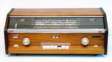
Cabinet and Controls
Made in 1963, this radio has the same general "toothy"
design as many European tabletops of the 1950s, such as
my Telefunken Gavotte. The cabinet
is made of solid wood, not veneer, and it appears to
have an oil finish.
As in the Telefunken, the bottom row of large pushbuttons
chooses the bands and inputs. The available bands are BC (AM), FM, shortwave,
medium-wave, longwave, and "trawler band" (marine communications).
Other buttons in this group select phono or tape inputs, and yet
another switches between internal
and external antennas. The leftmost "tooth" button is the
Rapido Sound control, which powers down part of the radio
and cuts off the sound while depressed—perhaps while you
answer the phone or attend to some other brief, urgent matter.
Two small pushbuttons right above the
bottom row are used to switch stereo and FM AFC on or off.
Separate bass and treble tone controls are located
on the bottom, at far left and far right, respectively.
The thumbwheel near the upper left is a stereo balance
control. The red and orange indicator lights on the aluminum trim
strip indicate power and stereo reception, and the
"magic eye" tuning indicator is mounted vertically
behind the dial, on the left.
The large knob on the right is the tuner. A single knob serves
as a tuner for both AM and FM, although the radio has separate
tuning mechanisms and dial pointers for those bands. Although
I haven't pulled the chassis to investigate, I assume some
sort of clutch disengages one tuner and engages the other,
when you switch bands. This scheme is unlike my Telefunken,
which has separate knobs for tuning FM and AM.
The large left knob is dual-purpose. Its inner
part controls on/off and volume, while the outer part
moves a cable to rotate a rod-shaped AM antenna inside the cabinet
for best reception. What with multiple tuners and
a rotating antenna, the cable routing inside this cabinet
is pretty fiendish to behold!
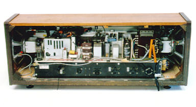
In the back view, you can see jacks for the various
inputs and for remote speakers. The tape deck connections
allow you to record off the air as well as play stereo
tapes. Other openings allow
you to choose various AC line voltages (important in
Europe) and to connect external antennas and a ground line.
The oblong slot near the top back allows one end of the
rotating AM antenna to protrude when cranked all the way over.
The speakers are mounted on the sides, as you can see.
The owner's manual recommends placing the set in a corner
of the room to deflect the sound toward the listener.
Electronics
I have the original owner's manual and service bulletins
for this radio,
whose design is complex and quite interesting. It's a
hybrid tube/transistor receiver, using nine tubes and
five transistors to provide FM stereo as well as multi-band AM.
The tube lineup is ECC85, ECH81, EF89, EF183, ECC83, ECL86,
ECL86, EM87, and EZ81. The transistors include three of type AF126,
two of type OC75, and one type AC125.
The transistors (and some other solid-state components) are all used
in the FM unit. In the rear chassis view,
the FM unit is the rectangular shielded box to the left of center,
with a few upright ventilation slots.
This radio is in fine shape and it played well from the day I
got it. The only work it needed was to replace the dial lamps
(three are required) and to rehang the white translucent sheet of
plastic that forms a backdrop for the dial. If you look carefully,
you can see the pilot lamps glowing in the
front view.
With lots of, well, everything inside, this is not a
particularly easy radio to work on. In addition to the owner's
manual and service manual, I have a brief service bulletin
which explains in several languages how to open the dial and get
the chassis out of the cabinet. Those are easy operations for
most radios, but far from obvious in this set, where
the first step is to carefully
pry off the aluminum trim strip in front, exposing hidden
screws inside.
The fact that Philips issued a special service
bulletin indicates that many repairmen must have
been just as mystified by the dial as I was before reading
the bulletin! Click on the icon to read the English disassembly instructions.
After I used the set for a few days, the FM suddenly
stopped working. Everything else worked fine, and the FM would
actually work for a second or two after the radio warmed up,
but then fall silent.
Not knowing much about European radios at the time, I asked fellow collector
Gerard
Tel for advice. He supplied an
instant diagnosis across the Atlantic, writing as follows:
As the AM bands are unaffected, the problem must clearly
lie in a section used only by the FM reception, so the FM
tuner and stereo detector are the first and main suspects.
(Though I have seen a radio fail on FM due to problems with
the ECH81, which didn't affect AM reception!)
You are probably aware that the ECC85 tube used in these FM
tuners are a constant source of headache; when playing on
AM the radio cuts off the B+ on the FM tuner, so the ECC85
is heated without current and this eventually kills the tube
somehow. The gain decreases until the point where it stops
oscillating, which kills the sound. It is not unheard of
that these tubes work for a few seconds after turn-on and then
enter their failure mode. ECC85 failure also explains why
the eye tube is non-responsive (I assume it does give response
on the AM bands?).
Sure enough, when I substituted a new tube, the problem
was cured. I used an American 6AQ8 to replace the European ECC85, since
the 6AQ8 is easier to find in the US and the two tubes
are equivalent.
In a followup message thanking Gerard, I asked about
the "Bi-Ampli" logo that appears on the dial. I had noticed the same term in his description of
a Philips BX998A on his website. Here is his reply:
The Bi-Ampli concept was introduced in the early
1950s to indicate separate amplification of bass and
treble. The BX998A has two output stages for this purpose.
Bass comes from the single-ended push-pull formed by 2xPL81
and trebles come from the EL84. Later, the term Bi-Ampli
was used to identify a family of fairly good radios, but
no longer related to the separation of frequencies. I
think in the 1960s there were no "real" Bi-Amplis
anymore, and your stereo set probably has two plain EL84,
one for each channel.
Checking the schematic, I found this to be true. Although
my radio still bears the Bi-Ampli name, it does not separately
amplify bass and treble frequencies. Oh well,
I suppose this is not the first—or the last—case
of a manufacturer milking a popular name for all it was worth.
This fine set now lives in our guest room, where it gets occasional use.
It never fails to impress visitors, showing that first impressions are
not always correct!
I have three other Philips radios: a beautiful
1954 LX444AB/01
tube portable,
a 1957 BD273U Philetta
and a 1954 BX135U. The
last radio is the same model used in a
television movie that featured my website.
|