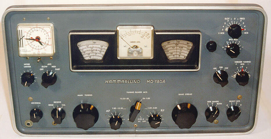
Hammarlund HQ-180AC Communications Receiver (1966)

This Hammarlund HQ-180AC radio was designed for serious
shortwave and ham listening. Built near the end of the great
age of tube-powered "boatanchors." It uses eighteen tubes and has special circuitry and controls that you won't find on consumer radios.
Description
The Hammarlund company made high-quality communications receivers from the
1930s through the 1970s. Model HQ-180A was made from 1963-1972. This
particular set was sold on September 16, 1966, according to its
manual, where the original owner wrote the date of purchase and serial number.
Model HQ-180AC is the same as HQ-180A, except it has an optional
24-hour analog clock/timer, visible at upper left in the front photo.
This radio is in nice original condition. Although it got a lot of use, according
to the previous owner, it was well taken care of. It doesn't have any
scratches, rust, or other marks of abuse.
The HQ-180AC offers continuous coverage of the broadcast frequencies from .54 Khz to 30 Mhz.
These frequencies are divided into six bands, which you select with the large rectangular
control in the center of the radio's faceplate. The tuning dials are keystone-shaped,
one to each side of the square signal meter in the center.
Controls
On the front of this radio are sixteen controls. Let's find out what they do, starting
with the tuners.
The main tuner is a three-section unit,
with brass plates rotating on a copper axle.
The knob is weighted with a heavy flywheel, for smooth tuning, and it drives the tuner
through a system of gears for accuracy. The main tuning knob is the large one
just to the left of the central bandswitch control.
To the right of the central bandswitch you'll see a second big tuning knob.
This is the bandspread tuner, used for fine tuning. Its variable capacitor is
another large, triple-section, gear-driven unit. The markings on the bandspread
dial are primarily for use in amateur listening, although you can also use it as a fine
tuner for shortwave listening.
The leftmost bottom knob controls another variable capacitor, the antenna trimmer, which
is used to match the characteristics of a particular antenna. In practice,
you tune in the station you want, then adjust the trimmer for the strongest signal.
At upper right, you'll find two more variable capacitor controls. The
topmost knob controls the 180's "slot frequency" setting. According to the manual,
this circuit "provides an extremely sharp slot or hole in the radio's selectivity curve."
It is used to eliminate heterodyning (squealing) or similar interference
when two stations are located very close together. Essentially, you
tune the main receiver to the station you want, then tune the slot filter to blank
out the interfering signal. This control has a little red pointer. For AM and
shortwave listening, you set the pointer to the far right or left, to keep
the "slot" from blanking out the station you're trying to hear.
Right below the slot frequency control is the BFO (beat frequency oscillator) pitch
control, which employs another little variable capacitor. When listening to
a CW (Morse code) signal, this control sets the pitch of the sound higher or lower.
Below the BFO control, at the far right about halfway up the faceplate, is the vernier
tuner, which controls the sixth variable capacitor. This one permits extremely
fine adjustment of the tuning, after you have found the station with the
main tuner (and bandspread, if applicable). Like the slot control, this one has
a little red pointer and its dial shows positive and negative values.
Whew! That accounts for seven knobs—only nine left to go!
The two knobs underneath the central bandswitch control are easy to understand.
The left one, labeled AF, is the audio volume. The right one, labeled RF,
turns on the main power and controls the strength of the radio frequency (RF) signal.
In normal use, you turn the RF control to the max, then adjust the volume with the AF control.
Below and left of the main tuning knob is a small control labeled Send/Receive/Cal. The
Receive position is for normal listening. The
Send position is for use with an amateur transmitter; in
this mode, most of the radio is powered down, but the tube
filaments are kept heated so it will come back instantly
when you are done transmitting.
When you switch into Cal, or calibration, mode, an internal oscillator
generates marker signals at every 100 Khz on the dial. The signals let you calibrate
the bandspread dial with the main dial for amateur-band listening. Once the
bandspread dial is set correctly, the markings on its dial show the correct
frequencies and permit very fine tuning. When Cal is switched on, twirling
the main tuner quickly produces a soft machine-gun effect, as the tuner goes fwoop-fwoop-fwoop
past all the marker signals.
Right under the square clock dial are two more knobs, for the noise limiter and AVC.
The noise limiter is the left knob. When switched on, it clips noise so that
the peaks of any interference signal are no higher than the wanted signal. This
can improve reception under noisy or weak-signal conditions. In practice, you
turn the noise limiter up until it just begins to reduce the wanted signal, then
back it off just a touch so that it clips only noise.
The right knob of this pair controls the automatic volume control (AVC).
A basic circuit found in most modern receivers, AVC automatically compensates for
the strength of various signals, so that a strong local station won't
blast your head off compared to milder signals. In consumer radios, AVC is always on.
The Hammarlund lets you turn it off, if desired, or choose from three settings (slow, medium, fast)
for different kinds of listening. The signal meter does not respond if AVC is turned off.
Like "magic tuning eyes," signal meters depend on voltages generated by the AVC circuit.
Only four controls left—we're almost done! Moving to the right again, the little knob
directly to the right of the bandspread dial moves the dial's center crosshair left or right.
I'm not positive why this is provided—perhaps this is used to adjust the dial in case
the radio is misaligned and
the dial marks don't exactly match the real frequencies.
Down and to the right, next to the vernier tuning control, is a three-position switch
that lets you select AM, SSB (single sideband), or CW (code) listening.
Two more knobs at the lower right are the sideband selector and bandwidth selector.
The bandwidth knob, labeled SELECT KCS, controls the bandwidth of the received signal.
Normally set to the widest (3 Hhz) position, for best audio, this can be set to
narrower bandwidths (.5, 1, 2) to reduce interference under poor conditions.
The sideband selector is set to BOTH for AM and shortwave listening. For amateur listening,
you can switch it to L (lower) or U (upper) sideband, depending on the situation.
Use
If you're thinking, "Wow, that sounds hard to use," you're partially right. Tuning
the HQ-180AC can involve several knobs, instead of one or two as in simpler radios.
But in good listening conditions, it's pretty simple. Most of the settings, such as
the bandwidth and AVC, you simply set and forget. To tune in a shortwave station, which
is how I use this set, you choose the band, locate the station
with the main tuner, then use the vernier tuner and antenna trimmer
as needed to fine-tune and peak the signal.
The ancillary controls are there to choose different kinds of
listening, and to give you extra selectivity and control
for pulling in distant signals.
Electronics
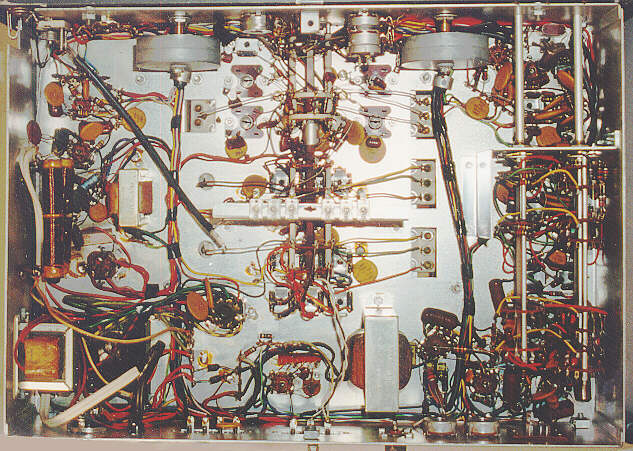
The electronics inside this set would practically fill a book. Come to think of it, they do!
The owner's manual for the HQ-180 series is about 80 pages long, with extensive descriptions
of the internals, including schematics of different sub-circuits, and of course
complete schematics and alignment instructions.
This radio is a "triple-conversion" receiver, with three intermediate frequency (IF) stages at 3035, 455, and 60 Khz. Most consumer radios have one IF stage. According to the book, "the third IF
is heterodyned with a high stability, adjustable oscillator which contains micro-accurate
vernier tuning control, located on the front panel." In other words, the third IF stage gives
you that great little vernier tuner.
Here's a list of the eighteen tubes and what they do:
-
6BZ6: RF amplifier
-
6BE6: 1st converter
-
6C4: HF oscillator
-
6BE6: 2nd mixer/crystal oscillator
-
6BA6: 455 Khz gate
-
6BA6: 455 Khz IF amplifier
-
6BE6: 3rd mixer/variable oscillator
-
6BA6: 60 Khz IF amplifier
-
6BA6: 60 Khz IF amplifier
-
6BV8: 60 Khz IF amplifier/AVC/AM detector
-
12AU7: SSB product detector
-
6AL5: Noise limiter
-
12AU7: BFO/signal meter amplifier
-
6AV6: 1st AF amp/delayed AVC clamp
-
6AQ5: Audio power output
-
0A2: Voltage regulator
-
6BZ6: Crystal calibrator
-
6CW4: Crystal oscillator
This radio has a complex power supply. In addition to the main
supply, it has a second, smaller supply that is always on when the set
is plugged in. The purpose of the secondary supply is to keep two critical
tubes heated at all times, to eliminate "drifting" problems as the set
warms up and stabilizes. If you are not going to use your radio
for a long time, you might want to unplug it, to prolong the
life of these tubes.
Furthermore, the main supply is connected through
the clock/timer,
which lets you turn the radio on through the timer. Plus, there's an
accessory socket in the back supplying B+ voltage and filament power for plug-in
accessories. And, finally, there's a "system socket" in the back with eight connections
(including power) for hooking up this set to a transmitter.
There's a lot more to say about the electronics,
but we'll stop here for
now. If you buy one of these radios, I highly
recommend getting your hands on a copy of the original manual.
Restoration
When I bought this radio, the owner said it had not been used in about eight years.
Before trying out the set, I did a lot of cleaning.
The faceplate and cabinet were the first to be cleaned up,
with my usual application of plain old soap and water, followed
by Novus plastic polish for the dial and clock plates and knobs.
Degreasing cleaner was used on the internals. In addition to
swabbing down and scrubbing the outsides of things, I pulled
every tube, cleaned its pins, and shot a little cleaner down
the socket.
I also spent considerable time cleaning the switch
contacts underneath the chassis. This radio has lots of switches,
which means lots of places for a dirty connection to
weaken or block a signal. Several of them, such as Select KCS
or the big bandswitch, are multi-stage or "gang" units,
which may switch several circuits in or out with each click.
Radio Shack sells a little spray can of cleaner with a
stiff brush at the end of an extension nozzle—very handy
for getting into those tight spots and removing stubborn
buildup or corrosion.
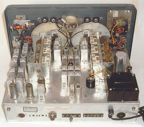
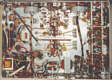
Cased entirely in ventilated steel, the top of this radio has a
big access hatch with a piano hinge in back. So
getting to the tubes for inspection or replacement is very easy.
Pulling the chassis out of the cabinet is simple, too. There are only four screws
to remove, then the whole radio slides out the front of the cabinet.
The only tricky
bit is maneuvering this heavy, 38-pound chassis out of the cabinet without
dropping it on the floor or scratching deep gouges on your worktable. I found it
easiest to do this while sitting down on a chair. I put the radio face-down in my lap,
then lifted the cabinet free from the back and set it down on the floor. Then I
just stood up with the chassis in my arms and carried it to the workbench.
When I first got this radio, I suspected that it
might be drawing too much power. After
replacing
the capacitors in the power supply and
checking out other power-supply components, I
verified that the power supply was working correctly.
Made in the 1960s, this radio does not have the wax
paper capacitors which cause trouble in so many old tube sets.
As you can see in the under-chassis photo, the small
capacitors are the reliable ceramic disc type.
After I replaced the filter capacitors in the power supply
and cleaned things up, it required no further restoration.
After using this HQ-180AC and my
HQ-160 over a
period of time, I grew to prefer the 160 as an everyday
shortwave receiver. The 160 offers a little more flexibility in controlling the audio,
which is important to me. Because
the two radios are so much alike, I eventually sold this
set at a radio swap meet.
|