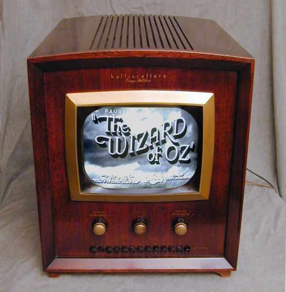
Hallicrafters Model 505 (T-54) Television (1948)


A striking early television, Hallicrafter's model 505 is unusual in several ways.
One glance at the small picture tube and the 13 tuning pushbuttons (including Channel 1)
tells you that this is no ordinary TV. The technology inside, as well as the external
appearance, are notably different from modern sets.
Early Television
Hallicrafters introduced its first televisions in 1947, amidst an explosion of postwar
electronic innovation. Although we may think of television as a fairly recent invention,
the technology began to develop in the 1920s. A special "Television
Number" of 1928 Radio News Magazine described
the early, electro-mechanical scanning disk television system.
The development of the cathode-ray tube (CRT) enabled all-electronic television,
with much larger and brighter picture tubes of the type used today.
Experimentation continued throughout the 1930s, but the TVs of that decade were fantastically expensive and
most people had no programs to watch! As late as 1939, there were only two TV broadcast stations in the
United States. When the US entered World War II, there were only a few hundred televisions in the entire
country, compared to tens of millions of radios.
All of this was changing by the war's end. By 1946, the nation had adopted a single TV broadcasting standard,
TV networks were springing into existence, and the refinement of all-glass miniature tubes made
it possible to build more affordable TVs. By 1947, the number of TVs in the US had
mushroomed from a few hundred to as many as 44,000. This encouraged radio manufacturers, including
Hallicrafters, to enter the TV market.
Description
Introduced in 1948, Hallicrafters' model 505 was a typical set of the time, with a number of miniature tubes
and a 7-inch electrostatic deflection picture tube. This type of picture tube was later superseded by the
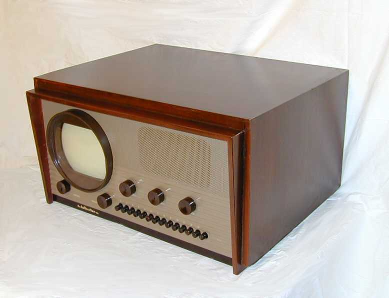
magnetic deflection type, which is still in use today. Model 505 has an attractive, mahogany colored
wooden cabinet with a slightly flared trim in the front.
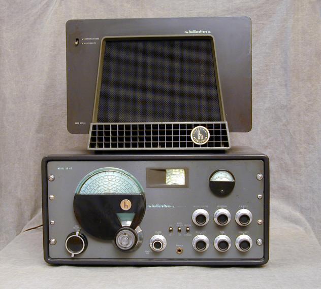
Hallicrafters sold this TV in a few different cabinets. The first was model T-54, introduced in 1947.
The T-54 came in the same grey metal cabinet as the popular Hallicrafters SX-42 communications radio.
Raymond Loewy, the famous Machine Age designer, is credited with designing both of these sets.
Below you can see my SX-42 radio and my unrestored
T-54 and
514 TVs.
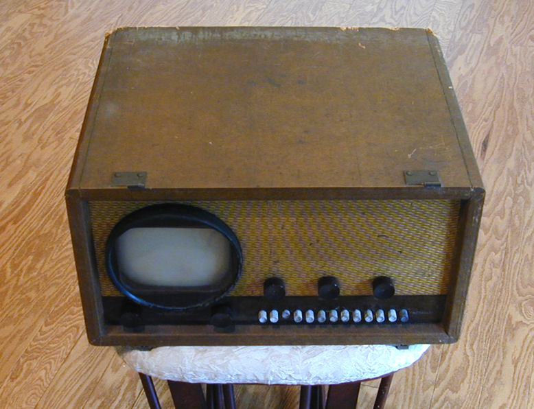
Model 514 was sold as a portable—or at least ""luggable"—set
with an oil-cloth covered wooden case and removable front cover.
Model 506 (not pictured) was similar to the 505 but with small wooden feet on the bottom.
Hallicrafters also licensed this television to retailers such as Sears and Montgomery Wards,
so you'll occasionally see a "clone" of this set with another maker's nameplate.
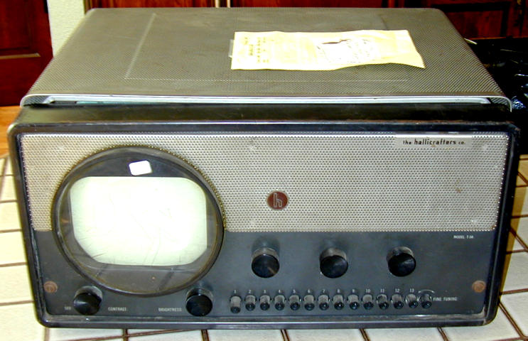
The 505's front panel is made of aluminum painted grey and beige, with ivory painted lettering.
A thick brown rubber bezel
cushions the round picture tube and creates a rectangular mask.
Although picture
tubes of the time were round, a television signal by its nature creates a rectangular
picture. Most TVs of that era used such a mask, and you would normally
adjust the picture height and width to fit the mask area. A "porthole" TV simply
had a round CRT with no mask. On such a TV, you can expand the height and width
to fill the entire CRT, but then the four corners of the picture will disappear
off the screen. By the 1950s, manufacturers developed rectangular CRTs
such as we use today, doing away with the need for such compromises.
The leftmost control combines the power switch and contrast control, while the
next knob to the right controls brightness. The three large knobs on the top
adjust the volume, horizontal hold, and vertical hold, respectively.
Below
these is a row of fourteen pushbuttons, for selecting Channels 1 through 13.
(Later models eliminated Channel 1 when that channel became obsolete.)
The rightmost "button" is a rotary fine-tuning control.
The back panel of the TV provides five additional picture controls, to adjust focus,
vertical and horizontal position, width, and height.
Disappointing First Look
This set was purchased as a Christmas surprise by my wife, but our first look at the set
was not encouraging. The TV had been shipped across North America, from New York to Washington
state. When I began to open the package and felt the small CRT in that distinctive position,
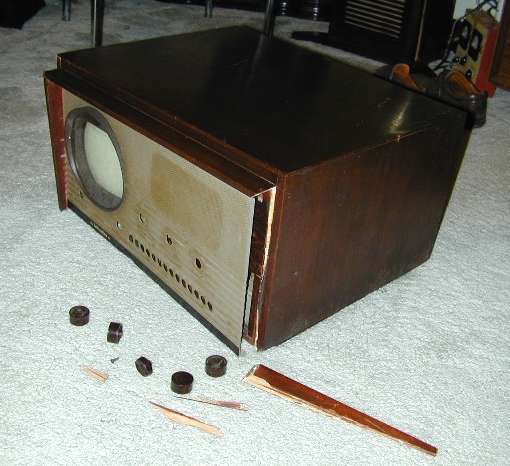
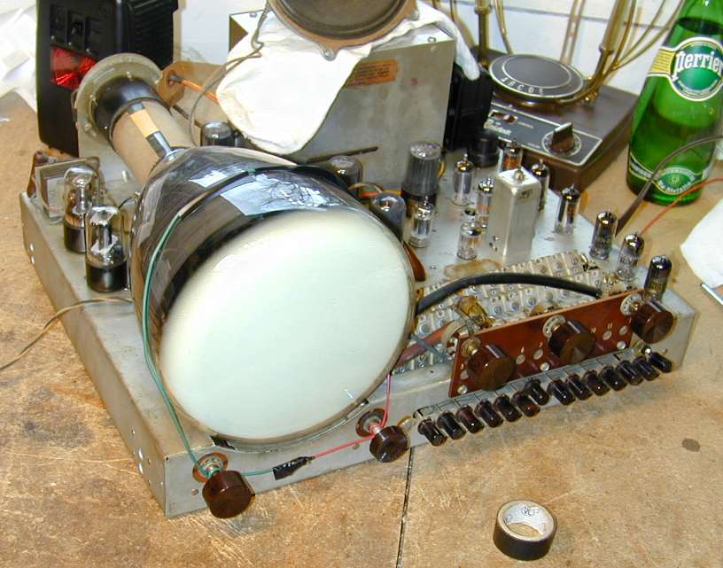
I immediately guessed what sort of TV it was. Opening the box revealed that it had suffered
shipping damage, however. Here is a view of the TV at that stage.
Shipped without adequate packing, the front trim of the cabinet had broken away and shattered. Worse,
most of the mounting brackets had broken loose from the chassis, allowing it to slide around in transit.
The metal front panel was pushed forward, knocking off all the knobs and breaking off the fine tuning control.
What a disappointment!
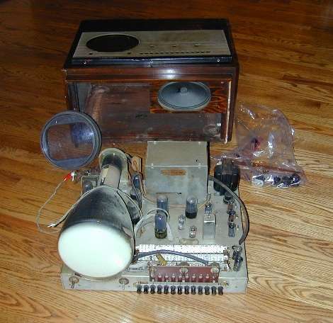
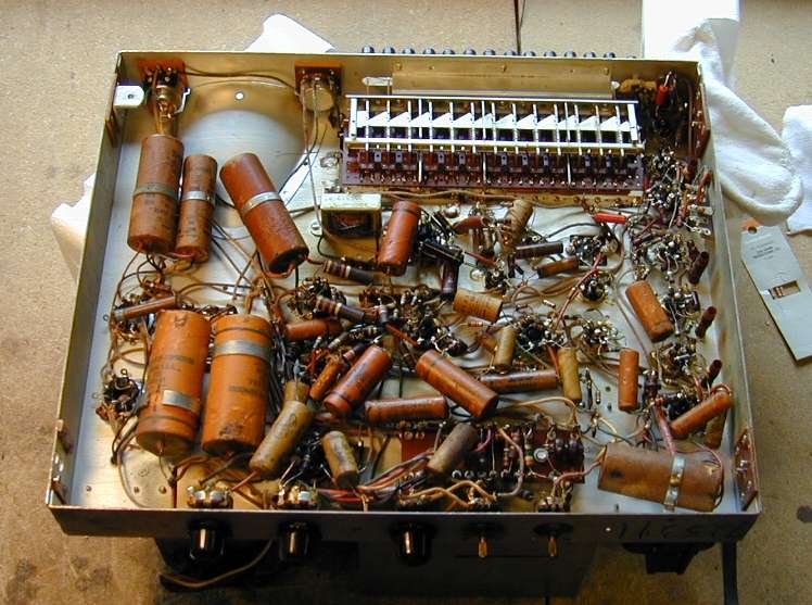
The next photo shows the TV disassembled after unpacking.
Despite the rough cross-country trip, the CRT and other tubes were unbroken and still in place.
Everything else—at least to the casual eye—seemed to be present and accounted for.
Rather than send it back for a refund, I decided to keep the set and restore it.
I brought the cabinet to a furniture shop to repair the breakage. They determined that the cabinet had been broken badly before.
Three of the four cabinet joints had been broken loose in the past—probably by dropping the TV on
the floor—and then crudely glued together. A proper repair would require knocking the joints apart,
cleaning off the old glue, and regluing everything. While the cabinet was off being repaired, I turned
to the electronic work.
Electronic Restoration
When I initially tested the TV under power, all of the tube filaments lit up, but it seemed
completely dead, with no sound and no hint of a picture. This didn't concern me too much,
since most unrestored 55-year old TVs will perform poorly, if at all.
Before doing any electronic work, I performed the usual cleanup and used electronic cleaner to clean all the controls,
tube sockets, and tube pins. This television uses 22 tubes, including the CRT. Here is the tube lineup:
| Tube |
Type |
Function |
| V1 |
6AG5 |
RF amplifier |
| V2 |
6AG5 |
Mixer |
| V3 |
6C4 |
Oscillator |
| V4 |
6AU6 |
1st video IF amp |
| V5 |
6AU6 |
2nd video IF amp |
| V6 |
6AU6 |
3rd video IF amp |
| V7 |
6H6 |
Video detector |
| V8 |
6AU6 |
Video amplifier |
| V9 |
12SN7GT |
Video out/Sync sep./DC rest. |
| V10 |
6AU6 |
Sound IF amplifier |
| V11 |
6AL5 |
Ratio detector |
| V12 |
6AU6 |
Audio amplifier |
| V13 |
25L6GT |
Audio output |
| V14 |
12SN7GT |
Horizontal oscillator |
| V15 |
12SN7GT |
Horizontal amplifier |
| V16 |
12SN7GT |
Vertical oscillator |
| V17 |
12SN7GT |
Vertical amplifier |
| V18 |
6C4 |
H.V. oscillator |
| V19 |
1B3GT |
H.V. rectifier |
| V20 |
25Z6GT |
Low-V. rectifier |
| V21 |
6X5GT |
Low-V. rectifier |
| V22 |
7JP4 |
Picture tube |
There are two versions of the model 505, early and late. Mine is the late version. The early version uses eight-pin 6SH7
tubes in place of the seven-pin 6AU6 miniature tubes. Both types are electrically very similar, but the
pinouts are different. If you compare both schematics, you will notice other minor
differences here and there, so it's important to get the right version; both are available from the
Early Television Foundation schematic archive.
One of my first tasks was to repair the fine tuning control, whose metal tab had been snapped off during
shipping. This was easy to solder back on, although it took a couple of tries to get it aligned straight.

The 7-inch picture tube is not mounted very securely. It simply lies in a recess in the chassis, held in place
only by its socket in the back, and by pressure from the rubber gasket
in front.
Before turning over the chassis, I strapped down the CRT by running wires around
it and the two nearest controls, securing the wire with tape. If you don't do this, you risk breaking the CRT pins
or the socket when you turn the chassis over. Another option is simply to remove the CRT while working
under the chassis, but then you need to flip it upright and reinstall the CRT whenever you want to test it.
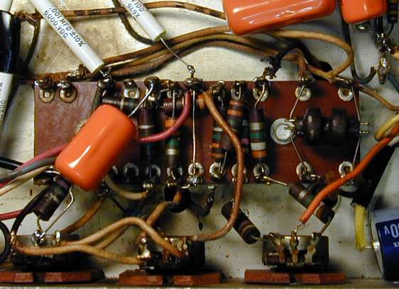
Below is a first look at the underside of the chassis, with its many paper capacitors.
In the upper left,
you can see one of the four metal mounting feet still in place. The other three had been broken off
their riveted phenolic chassis mounts, allowing the chassis to slide around in the cabinet.
In addition to large electrolytic capacitors, this television uses huge paper capacitors
to couple the vertical output to the CRT. They are the two, almost soda-can sized
capacitors near the left. When this photo was taken, I had already cut the metal
mounting bands from the leftmost capacitor, prior to replacing it. (For a description of routine
capacitor replacement, see the article Replacing Capacitors in Old Radios.)
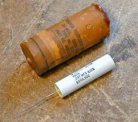
The next photo shows the high-voltage capacitor after removal, looming over its more compact modern replacement.
These capacitors are rated for 6000 volts, much higher than what is used in radio repair and
most TV circuits. I was able to find replacements at Allied Electronics.

After replacing the capacitors in the power supply and high-voltage circuits, I again
tested the TV. As before, it had no sound or picture. Checking the low-voltage power supply,
I found that it had reasonable B+ voltage. The filament supply was also reasonable.
This TV, by the way, has no power transformer. Like other 7-inch televisions and countless inexpensive radios, it has an
"AC/DC" type design, with the tube filaments connected directly to the AC line.
Replacing Cannibalized Circuitry
Puzzled by the lack of sound, I made a quick check of the audio output, touching the tip
of my soldering iron to the center terminal of the volume control. The result was a loud
buzz, indicating that this circuit, at least, was functional.
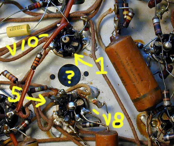
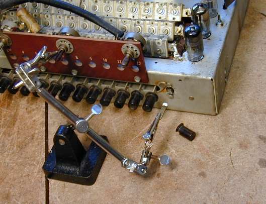
Looking more closely at the sound circuitry, I noticed something surprising. Pin 1 of V10,
the sound IF amplifier tube, was not connected to anything! Since pin 1 is the grid, or input
pin for this tube, that explained the absence of sound. What's more, I saw another snipped-off
lead on pin 5 of V8, the nearby first video amplifier tube. And a suspicious looking empty hole
was located between those two tubes. The next photo shows this part of the chassis.
Referring to the schematic, I discovered that someone had removed three coils and several
other components, cutting off both the audio and video signals at this point. This was
pretty discouraging, since I had no clear idea what the missing coils even looked like,
much less how I might replace them.
Calling on the rec.antiques.radio+phono newsgroup for advice, I soon learned that the
missing coils were fairly generic in nature.
One of the group members, Bonita Lee Geriac, was kind enough to scrounge me some
replacements from a junked TV and send them in the mail.
In addition to the parts, Bonita sent me instructions on how to install them, as well
as a copy of the schematic for this version of the TV. (My schematic showed only the
earlier version.)
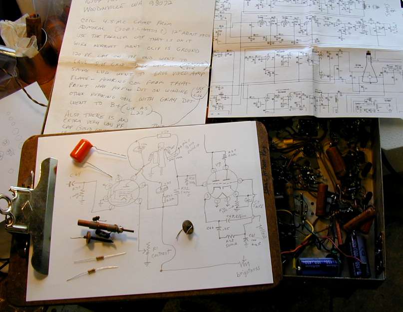
To make sure that I installed everything correctly, I made a drawing of the actual
connections found in my TV, indicating how to install the scrounged components. Below
is a view of the notes and the "new old" components.

Two of the missing coils were peaking coils for the video signal. This type of coil is essentially
a resistor with a coil wound around the resistor body. It is small enough to be wired point-to-point,
as you would any small resistor.
The third coil was a larger, adjustable coil, which couples the 4.5mhz audio
signal to the audio circuits and also serves as a trap to prevent audio from leaking back into
the video circuits, where it would cause interference.
The mysterious hole between tubes V8 and V10 is where this coil had been mounted. Like other
adjustable coils, it needs to be mounted with its adjusting screw accessible from the top
of the chassis. I fashioned a small mounting plate from a piece of soup-can metal, cut to
the right shape, epoxied to the chassis, and drilled with the correct size hole (5/16 inch)
to fit the coil's clip.
Carefully following my notes, I installed the new parts and cautiously powered up the set.
For the very first time, I was rewarded with signs of life! The sound came through loud and
clear on all local channels, and the fine tuning control affected the auio as expected.
This was excellent
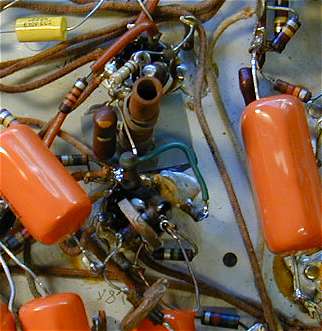
news, since it meant some major chunks of circuitry were operational. The next two photos show
the freshly installed components from below, and the sound takeoff coil from above the chassis. The upright
brown cylinder near the middle of the first photo is the sound takeoff coil.


The next phase involved replacing all of the remaining paper capacitors, including those hidden
under the phenolic board in the base of the high-voltage cage.
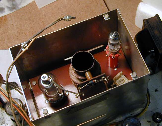
Inside the High-Voltage Cage
The high-voltage cage is located near the back of the receiver. It contains the 6C4 HV oscillator tube,
a 1B3GT HV rectifier tube, the HV coil, and a few other components. The next photo shows the cage
from above, at a time when I had mounted the 6C4 tube in an extender socket for testing its voltage readings.

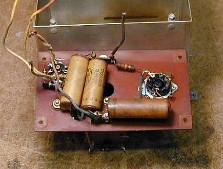
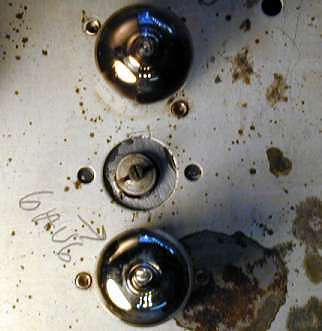
To remove the high-voltage cage, you must carefully unsolder several leads which run
through holes in the chassis to a phenolic board underneath. The next photo shows this board.

After marking and unsoldering those leads, you can unbolt the cage from the top of the chassis
and carefully draw it upward. Be careful not to yank too hard on the leads, which are stiff
and will tend to bind in the narrow chassis holes. Then you can remove four screws inside the
cage and take out the board itself.
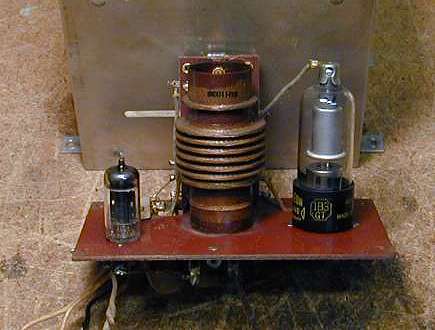
The next photo shows the high-voltage board removed from its cage. In the middle is
the HV coil, which we'll return to later. Its complex construction
with stacked windings makes it nearly impossible to replicate.

Hidden under the HV board are three paper capacitors, as seen in the next photo. One of them
is another 6000-volt rated capacitor.
The following picture shows the HV board after recapping.
Getting the h-v board back onto the cage is trickier than pulling it off. Threading the
old, bent, stiff leads through the bottom of the cage proved almost impossible, even using
a strong light and long, narrow tweezers. I solved the problem by tack-soldering each lead onto a
long, thin piece of wire about two feet long, threading each wire through the appropriate hole,
then carefully pulling the board with its leads back into the cage.
After the board was
bolted back in, I used the same procedure to thread the leads back through the chassis.
Then I unsoldered the temporary wires and reattached the leads to their original terminals.
Because this is a finicky procedure, you might be tempted to skip it altogether, but I advise against that shortcut.
It's vital to replace the old capacitors in this cage if you want your set to work reliably.
My Kingdom for a Raster!
At this stage, I was getting desperate to see some kind of image on the CRT. Probably not a recognizable picture,
but at least a glimmer . . . a horizontal white line . . . a dot in the center . . . something!
All of the paper and electrolytic capacitors had been replaced, and I had restored the cannibalized
circuitry as best I knew how.
What a disappointment it was when I finally fired up the set and got
exactly the same results as before. Great sound on all channels, not a hint of light on the picture tube,
no matter how I adjusted any of the picture controls.
Since it was nighttime, I turned off the shop lights to doublecheck that all the tubes,
including those in the high-voltage cage, were lighting up. When I turned off the last light, I was
amazed to see a faint image on the CRT. There had been an image all along, but it was so faint that
even a single light in the room washed it out completely.
Encouraged, I started fiddling with the picture controls, and soon had a watchable image. The next
photo shows the CRT at this stage, displaying an image from the 2002 Academy Awards ceremony.
Okay, so that's not the greatest picture you've ever seen! But if you have ever
tried to fix an old tube TV, you know that almost everything in the set has to be working
reasonably well, just to obtain even a feeble picture like this.
I still didn't have a workable television, however. A picture that's invisible in normal room light is
not acceptable.
The next logical step was to test the set's high-voltage
output.
Caution: testing the high-voltage circuits on any television is potentially dangerous. Don't attempt
it unless you have the correct equipment and some
experience working around high voltage. You cannot use an
ordinary voltmeter for such tests. I used a special high-voltage tester made by Pomona Electronics, shown in the next photo.

The results were disappointing. Where the schematic indicates 5-6 kilovolts, I measured only
2 kilovolts. This alone might account for the dim picture.
I spent some time rechecking my
work and checking other components such as associated resistors, but found nothing suspicious.
I even disconnected the high-voltage output lead and checked the voltage again, in case
something was loading down the output.
Inside the HV cage is a small trimmer capacitor that can be used to adjust the output.
Adjusting this trimmer made no discernible difference in the output. I also used a frequency
counter to determine the frequency of the high-voltage oscillator. Depending on the trimmer
setting, I found that the best picture was obtained with a frequency between 185 and 200
KHz, a value that is consistent with this type of oscillator, according to my old TV
manuals.
Of course, a worn-out picture tube can also be responsible for a dim picture. Unfortunately, no
CRT testers are capable of checking an electrostatic deflection tube. The only practical
test is to try it out in a working TV that uses the same tube.
I placed an ad on my website's
free ad page (which has since been discontinued), seeking someone in the area with a working 7-inch TV. To my amazement, the ad
was answered the very next day, by a fellow collector who owned a restored Hallicrafters 505
and who lived only about two miles from my house!
I rushed over to the house to make the test. Before installing my tube, we powered up his
working TV so that I could see how bright a normal picture should be. Then we slid the
chassis out of the cabinet, installed my tube, and fired it up again. The picture was
completely dark. Turning out all the lights, we saw a faint image, exactly as in my set.
My CRT was clearly a dud. Over the next several weeks, I spent some time checking out the high-voltage
power supply, which stubbornly refused to produce more than about 2 kilovolts. I also acquired a
couple of fresh 7JP4 picture tubes and restored a Motorola VT-73,
another 7-inch electrostatic deflection set.
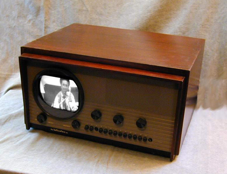
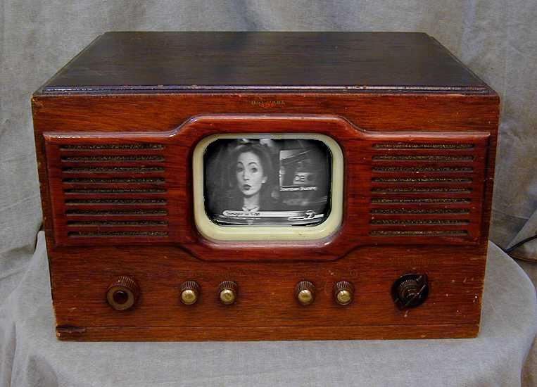
The final photo shows the TV in operation, using a strong CRT.
It's watchable, but not the brightest of my 7-inchers, probably
due to inadequate high voltage.
Low High Voltage?
The high-voltage supply in these Hallicrafters TVs (and similar Philco 7-inch
sets) is problematical. In many cases, including mine, merely restoring components to
original values doesn't produce the required voltage.
The culprit is the HV coil, which appears to lose its oomph over time,
perhaps because it absorbs moisture. Collectors have tried various remedies, such as
baking the coil and recoating it, modifying circuitry to boost the drive voltage,
or even installing a substitute high-voltage supply.
Tom Albrecht found a solution that seemed to fix the problem permanently.
He installed a little muffin fan in the HV cage and lifted the lid a
bit to improve ventilation. You can read more in his
VideoKarma discussion.
TV-7W, Anyone?
After finishing the Halli 505, I got yet another 7-inch TV, a 1948 National TV-7W. Read
that article for some comparisons between these competing models.

Or, How About a T-67?
A couple of years later, I found another 1948 Hallicrafters, a
10-inch T-67 tabletop. Using a very
different design, it makes an interesting contrast to the 505.

|