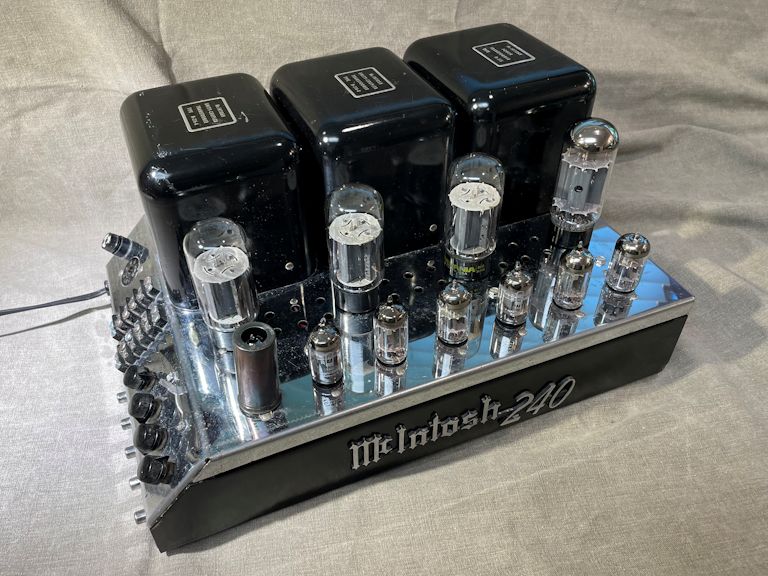
McIntosh Model MC240 Power Amplifier (1965)

The McIntosh MC240 stereo amplifier is a classic from the golden years of tube audio,
a top seller in its time and prized nowadays by collectors and audiophiles.
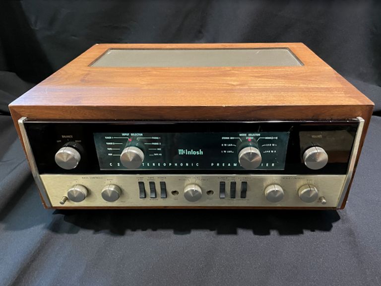
I bought this amp in 2021, with a companion
McIntosh C22 preamplifier.

I restored both of them and now they operate as a pair in my workshop, where
I spend a lot of time.
MC240, the Celebrity's Choice
Some people consider the McIntosh MC240 the finest power amplifier
of its time, period.
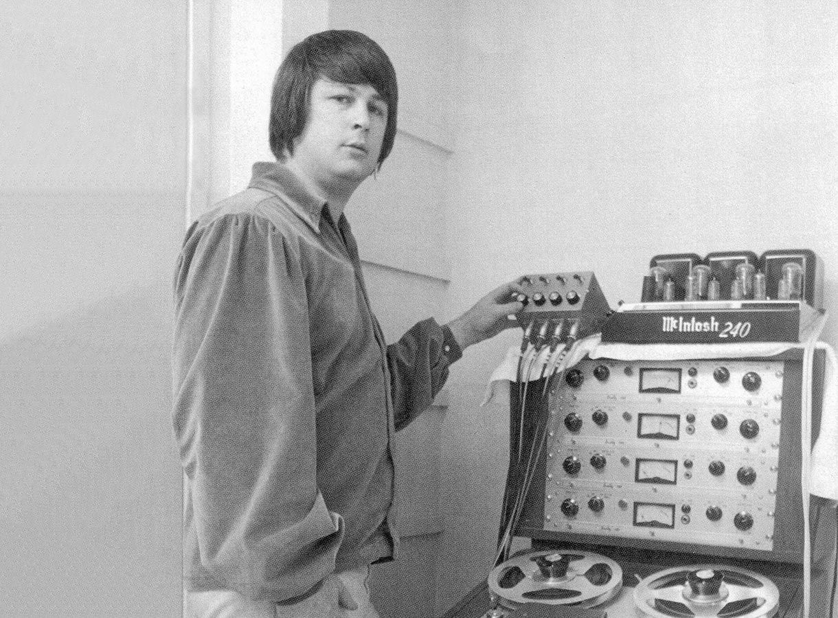
What kind of people, you ask? These pics from the McIntosh factory website
show who used the MC240 in the 1960s:


Yes, that's the legendary Brian Wilson using an MC240
while producing the 1966 Beach Boys album, Pet Sounds. And yes, that's the
Woodstock (!!) performance stage in 1969. (Look closely at the Woodstock pic, and
you'll see Joe Cocker performing at center stage in his tie-dye
shirt and signature laid-back posture.)
Wilson and the Woodstock producers could
afford any equipment in the world—and they chose the MC240. Case closed!
I suppose that fictional detectives don't really count, but if you watch
the Bosch TV series, you'll see that jazz fan Harry Bosch's
stereo setup features an MC240 amp (far right) and a McIntosh MX110 preamplifier:

Joking aside, if you're lucky enough to own an MC240, you're in good company.
Technical Description
Here is the MC240 owner manual, with detailed technical info and
operating directions:
The manual gives this basic description:
The MC240 has on one chassis two 40-watt power amplifiers. In addition to use
as a stereo amplifier, the flexibility of the MC240 permits it to be used as
a monophonic amplifier that delivers 80 watts, or as two separate 40 watt
amplifiers with each channel amplifying completely separate programs, or
as two amplifiers for use with an electronic crossover network.
This diagram of the MC240 panel shows the input jacks at the right and
the speaker terminals near the center:
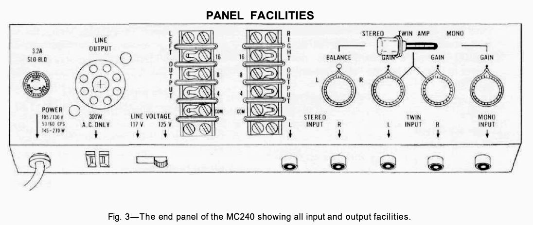
The mode switch at upper right of the panel flips the amp between its
different operating modes: stereo, twin amp, or mono.
Like the vast majority of MC240 owners, I only care about stereo mode.
However, the twin amp and mono modes made the MC240 adaptable to
institutional and commercial applications such as school intercoms, PA
systems, or movie theater audio.
Here are two service manuals: the McIntosh factory manual at left, and Sams on the right:
When this article refers to parts inside the amp, I'll use part numbers
from the McIntosh factory schematic.
In case you're wondering what makes the MC240 so special, here is a
technical description
from the owner manual that explains, in the designers' words, what
sets it apart from other power amps of the day.
Finding a McIntosh MC240 Amp
In September, 2021, I was contacted by a guy near Chicago
whose late father left him the contents of a radio/TV repair shop.
He wanted to sell this assortment of old radios, hi-fi gear, and parts.
I gave him my standard advice about how to dispose of such a collection.
And I mentioned that I might be interested in vintage McIntosh tube gear,
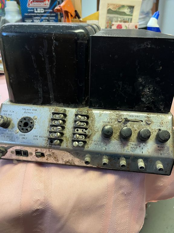
if he had any. He sent back these photos of a 1960s MC240 amp that
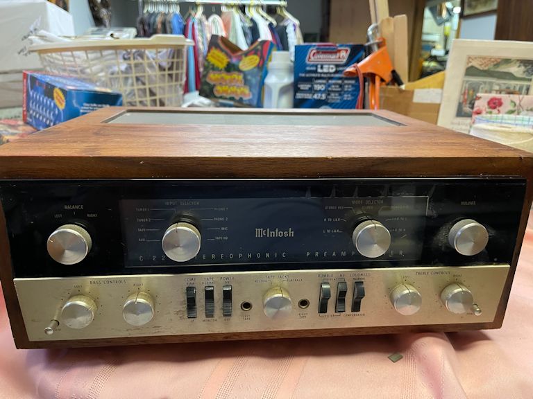
looked dirty but complete. Other pics showed a C22 preamplifier
from the same era, making it a perfect companion.

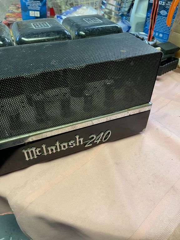
The amount of dirt suggests that this amp sat in a grubby place for a long time. No
doubt the chromed chassis has some surface rust under the dirt, but I have seen worse
rust in my time, and I never let mere grime get in the way of a good restoration!
We agreed on a price for both items.
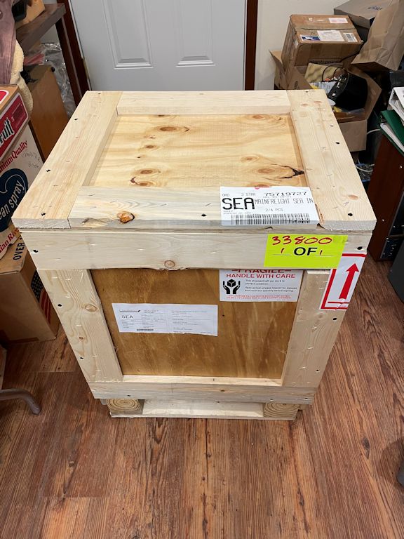
I contacted the Craters & Freighters
shipping company and arranged for them to pick
up the units in Illinois, build a crate, and ship it to me in Washington state
(at a cost of just under $1,000).
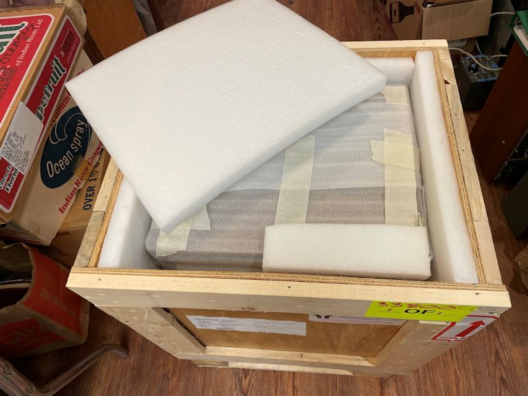
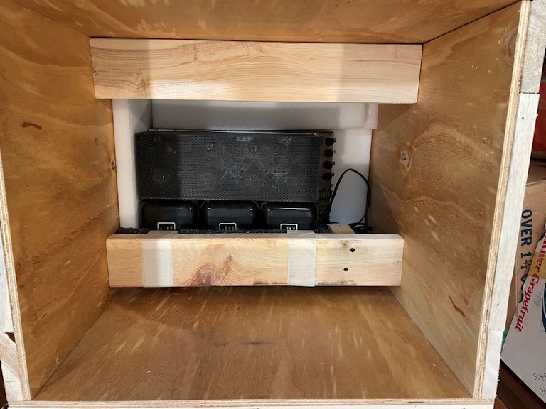
The shipment arrived in a few days. The packers built both items into a heavy
double crate, padded with layers of high-density foam. Above, in the "upper story,"
was the C22 preamp. Below, resting under heavy cross bars, was the MC240 amp.


Thanks to a stellar packing job and careful handling, everything arrived intact.
First Look
Let's unwrap the goodies and take a peek!
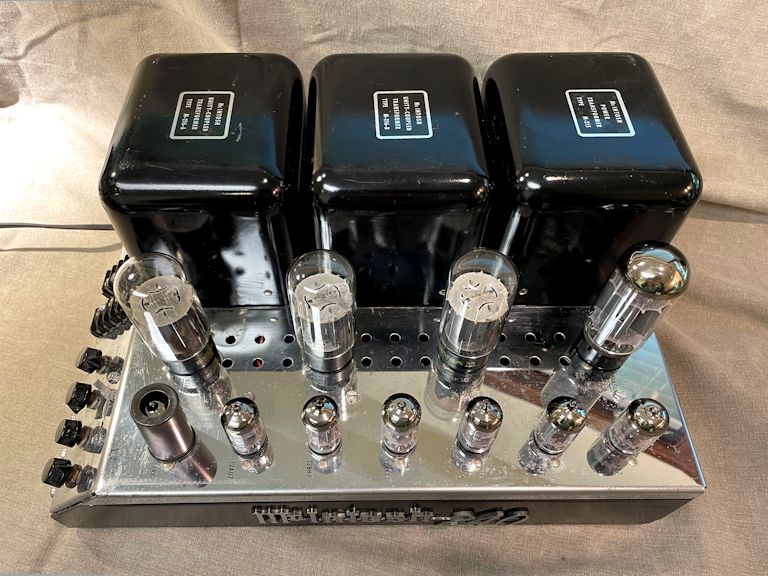
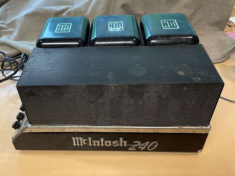
At first glance, my MC240 doesn't look bad:


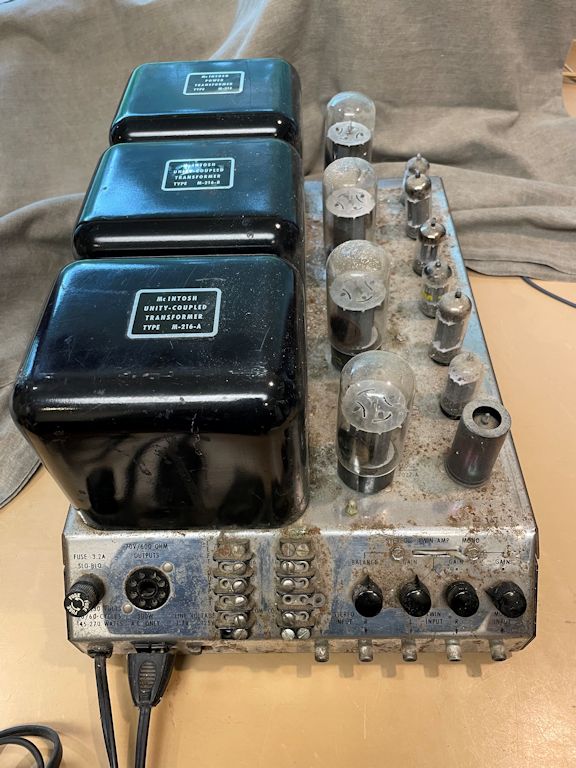
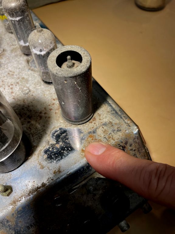
Er, not so pretty here. Popping off the tube cage reveals some serious grime:
The chrome chassis is layered with crud, as if the amp was stored in a barn or unheated outbuilding.
This dirt comes off easily, as I can tell by rubbing with a moistened finger, but
under the dirt is surface rust that won't yield so readily.
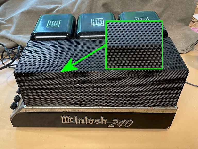
McIntosh released three versions of the MC240 (early-middle-late)
during its 1961-1969 product lifetime. Two telltale signs identify this
as a late-version MC240 from 1965-1969.
First, the tiny holes in the tube cage are round,
whereas earlier versions have square vent holes:

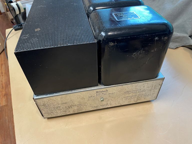
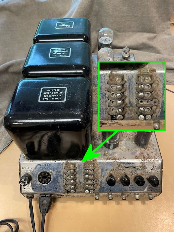
Second, the speaker terminal strips are located near the middle of the control panel,
rather than the left side, as in earlier versions:
You can read more about MC240 versions at the
McIntosh Compendium.
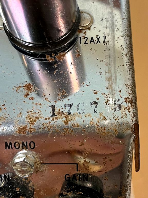
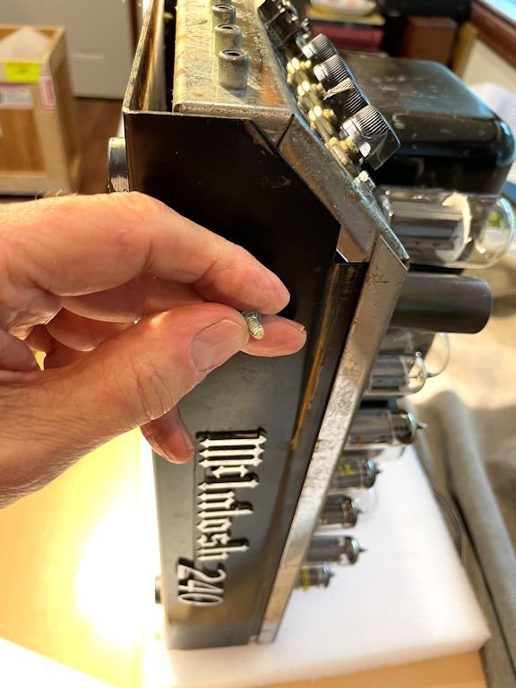
As with many MC240s, the rubber-stamped serial number on the corner of the
chassis is worn, but I can see the characters 1-7-G-7-5:
Serial numbers for late-version MC240s have five digits within the range
10G01 to 58G76, and 17G75 falls roughly one-fifth of the way
through that range, so I'd guess 1965 as the likely manufacture date.
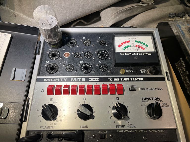
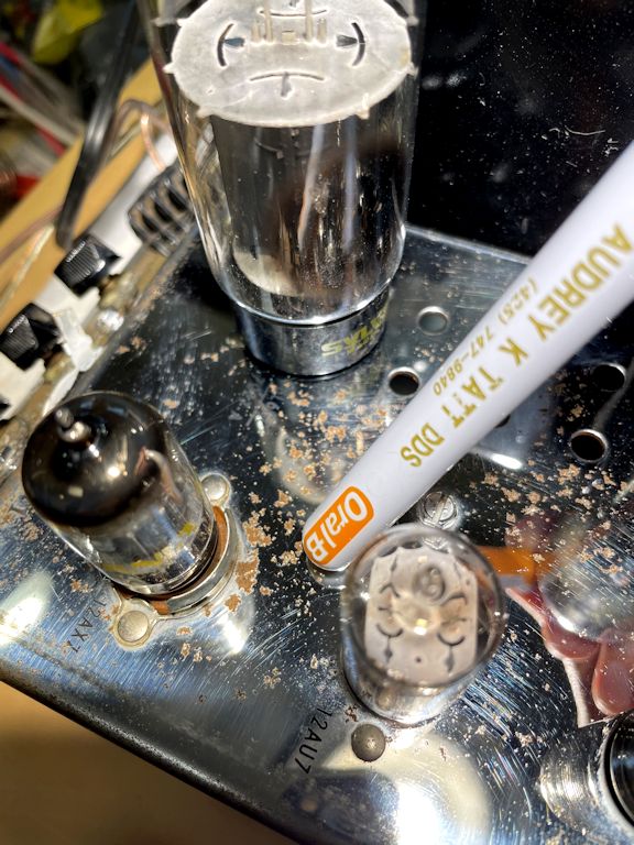
Before digging into the chassis, I tested all the MC240's tubes. This
6L6 output tube looks strong:

Most of the smaller tubes were also usable, but I'll probably splurge
on a new set for this tasty amp, and reserve the usable pulls for
use in other projects.
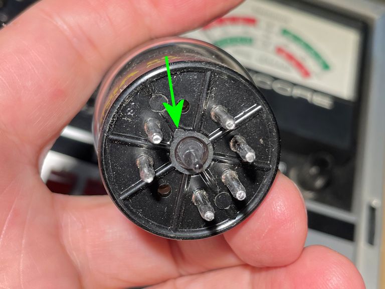
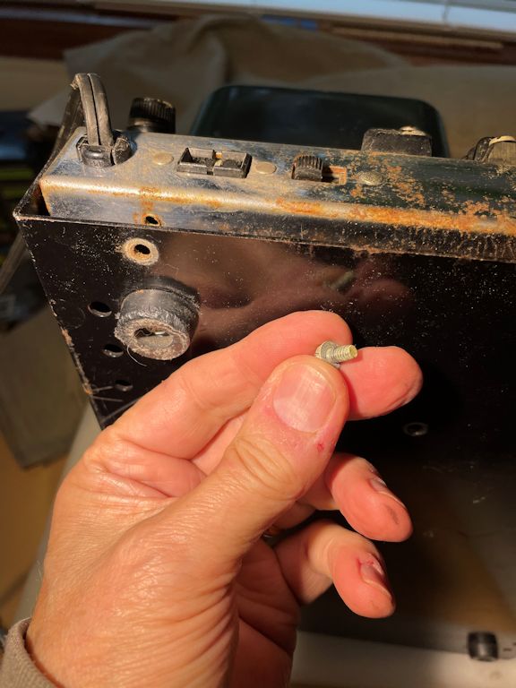
One of the 6L6 output tubes had a broken key on its underside. In this
photo, the entire key is broken and lost, leaving only its outline on
the tube base:

The key on an octal tube base guarantees correct orientation when you plug in the
tube, so that tube pin #1 goes into tube socket #1, and so on. If the key is
missing, then you might accidentally insert the tube with
a wrong orientation, so that pin #1 could plug into any random socket hole.
In such a case, the tube certainly won't work and it might even self-destruct.
Not surprisingly, that tube tested dead, so I borrowed a 6L6 from my
Scott 800-B.
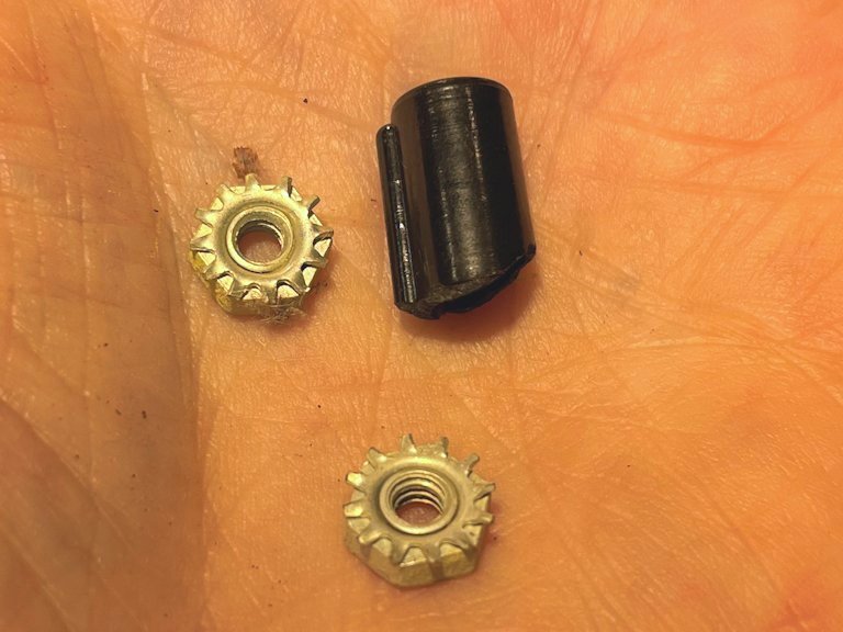
When I opened up the amp's chassis, I found the missing key fragment, along
with a couple of loose nuts from the speaker terminal assembly.

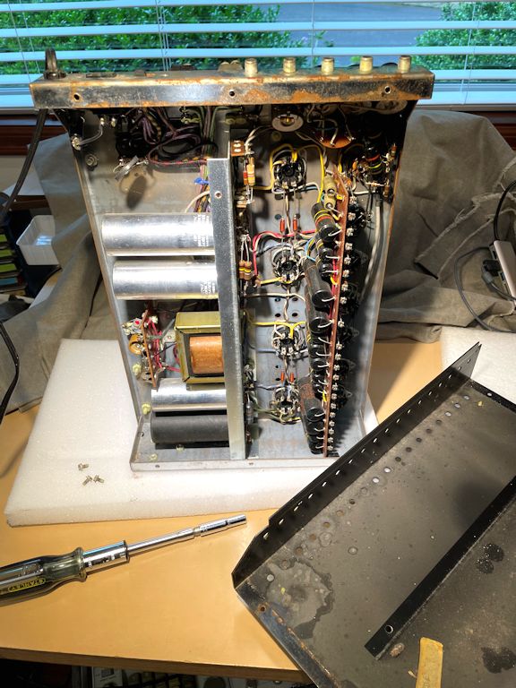
To pull the chassis cover, stand the amp on end, with its
power transformer resting on the workbench. That looks precarious, but the weight
of the massive transformer keeps it steady. Remove four screws from the bottom and slide
off the cover. You don't need to remove the rubber feet.
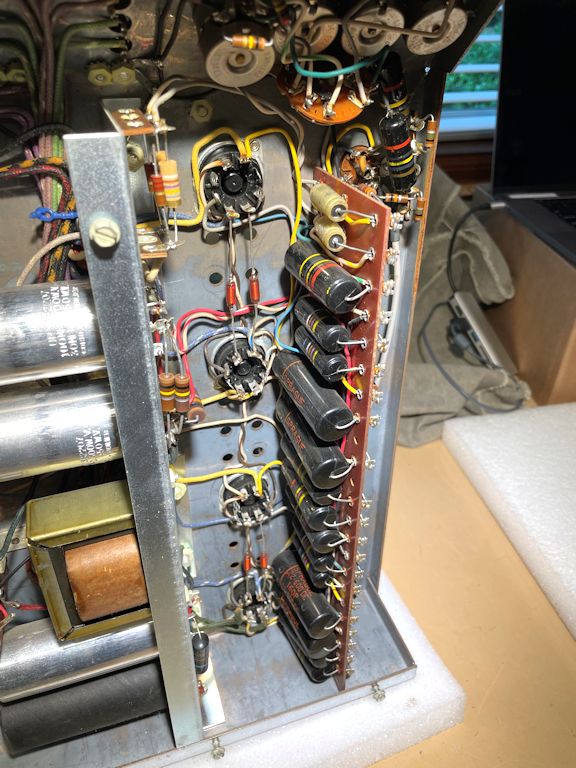
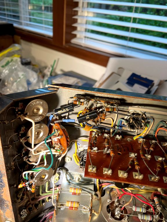
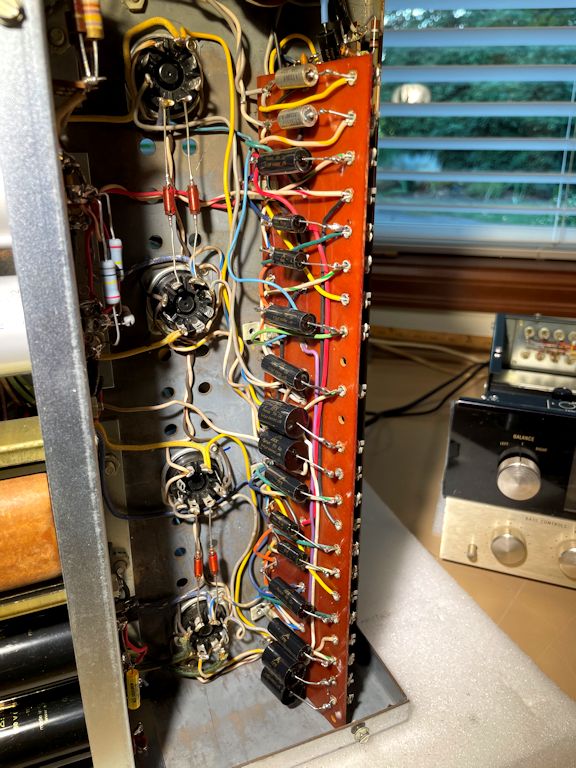
Here's our first look at the MC240 innards. The construction quality is superb,
more like military grade than consumer grade: notice the rational layout and super-tidy
workmanship. The jumbo phenolic board holds capacitors on one side, resistors on
the other—what could be more logical?
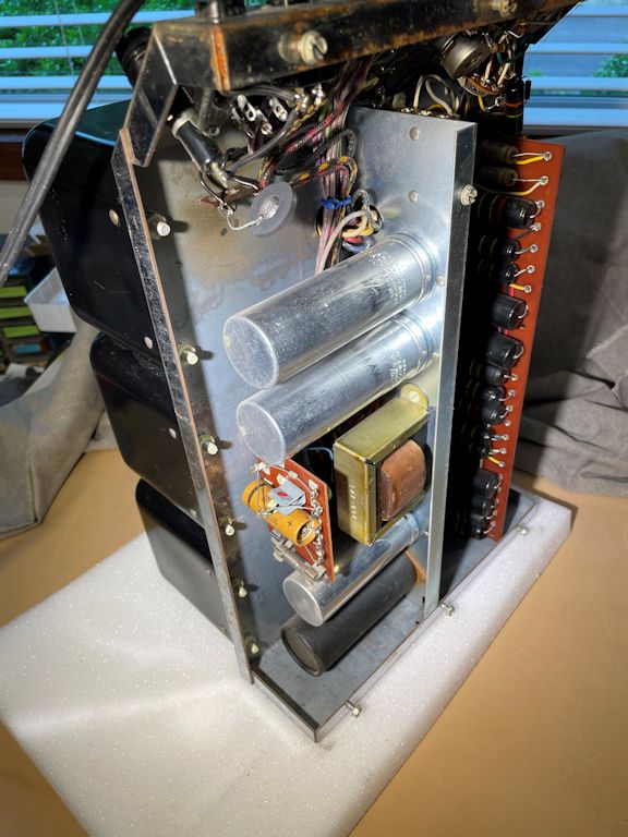
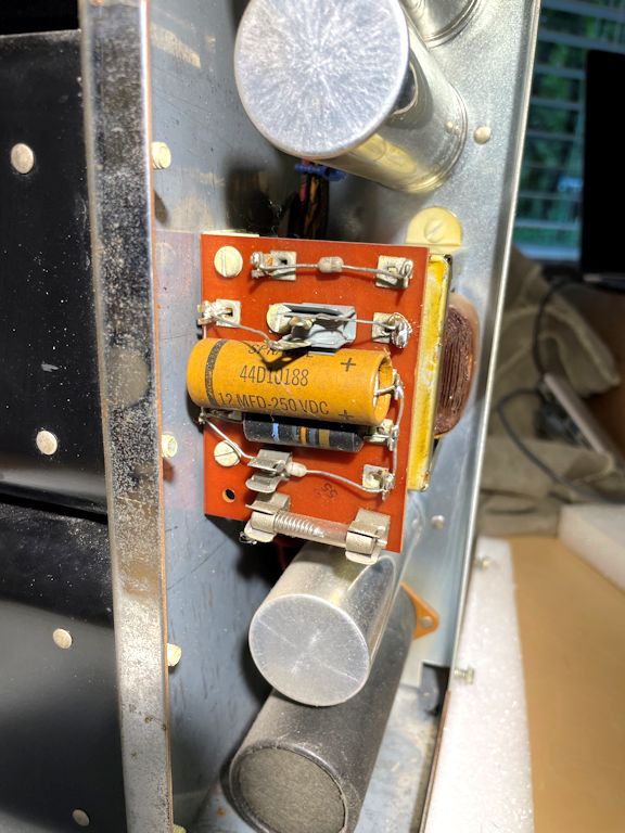
A second, smaller phenolic board holds components for the amp's voltage
doubler circuit. This board has two capacitors, two diodes, a selenium
rectifier, and a fuse. I'll replace everything but the fuse.
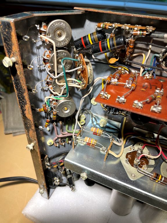
The next pic shows the backs of the amp's control panel. I'll apply electronic cleaner to
eliminate any pops and scratchiness in these controls. (You can read more about
such routine cleaning in my first steps
in restoration article.)
The two striped cylinders in that photo are "bumblebee" type paper capacitors.
Despite the plastic shells, they are just as unreliable as older-style wax paper caps.
I'll replace them, along with every other paper and electrolytic cap in the amp.
Recapping is a standard restoration step for every tube device of this vintage, as explained
in my recapping article.
Some unrestored tube devices will operate (at least, somewhat) without such
recapping. This MC240 was capable of that, in fact, as we'll learn shortly. But it's risky
to play the amp in that condition, because old
capacitors can fail suddenly, without warning, and damage other
"unobtanium" components like the power transformer.
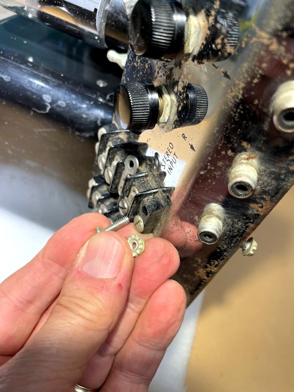
The next photo shows where the two mysterious loose nuts came from. They belong on the ends of
screws in the speaker terminal block. Somebody loosened those two screws too much, and
their nuts fell off into the chassis compartment.
First Trial
Inspecting the innards hadn't revealed any obvious horrors, like broken or missing
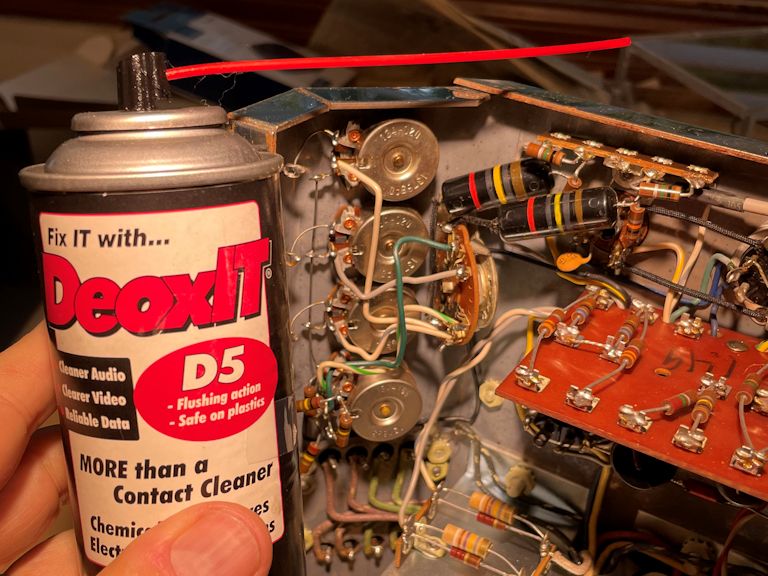
parts, and I'm itching to try out my amp. But first, I'll clean the the control potentiometers
and the mode switch with DeOxit electronic spray. To catch any drips, I stuffed a
short length of wadded paper towel under each potentiometer case:


I spritzed a little cleaner into an opening in each case and worked the
control all the way back and forth a bunch of times. The exposed contacts on
the mode switch were easier to reach with a Q-tip dabbed in DeOxit.
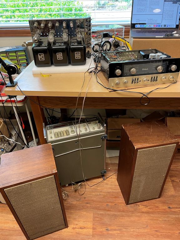
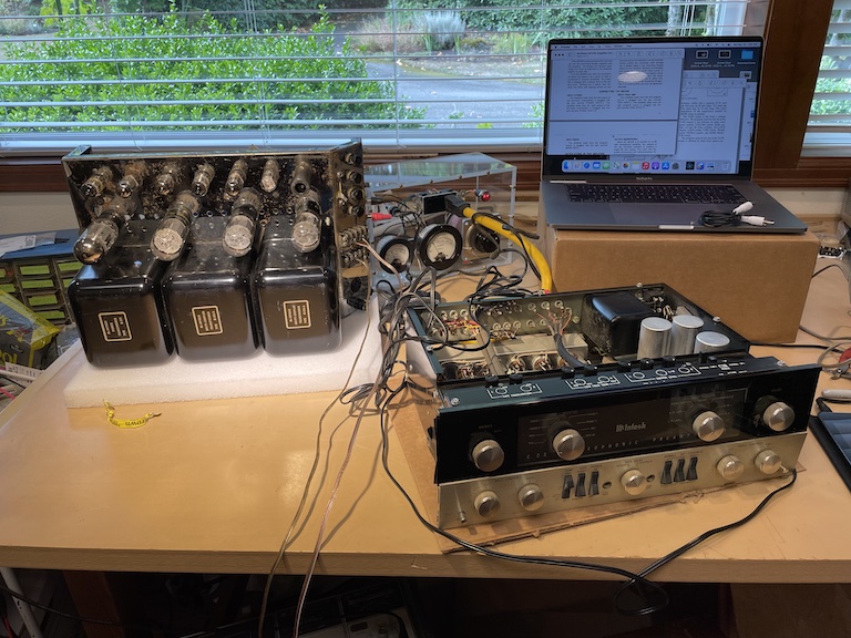
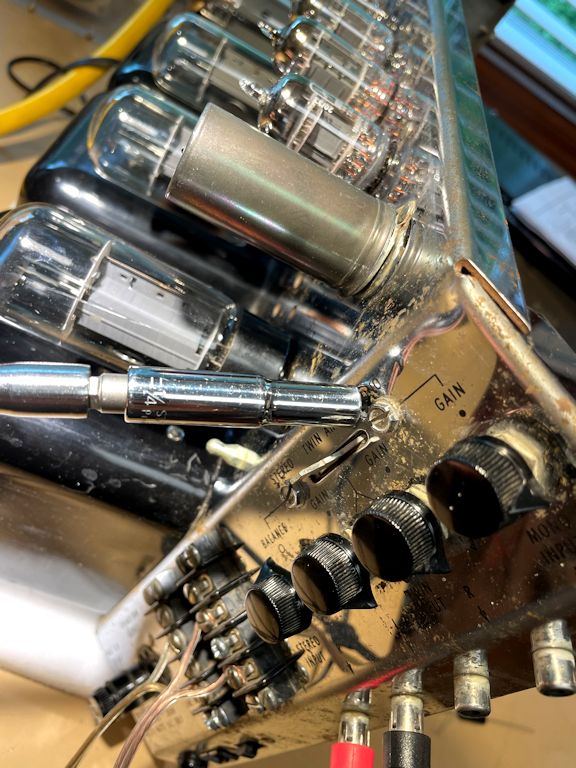
Now I'll do a controlled trial, using my metered variac
to gradually increase the AC line voltage while monitoring how much current the
amp draws. The variac is seen behind and slightly to the right of the amp in
these photos:

Connected to the amp, farther to the right, is the C22 preamplifier that I bought
at the same time. I could have tested the MC240 amp in isolation, but it's more fun
to try them both at once. At this point, I had also cleaned the controls, etc., on
the C22.
The trial results were encouraging! With both units switched on, I gradually turned
up the AC voltage on the variac, with an eye on its ammeter. The current consumption was
normal and, after a slow warm-up, the amp and preamp played well, with nice fidelity
and loads of volume. If I can avoid messing things up during restoration, they
should sound even better and play reliably for decades to come.
Rebuilding the MC240 Power Supply
As in all restorations, I'll start by rebuilding the power supply. Everything
else in the amp depends on the p-s, and after this section has been made safe
to use, I can confidently power up the MC240 for periodic testing
while I replace more numerous components in the amp's signal path.
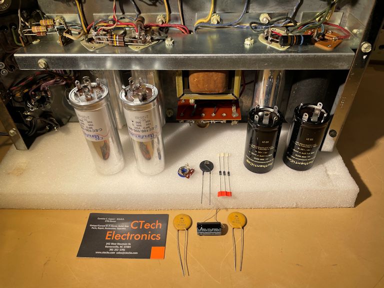
For this phase, I bought a MC240 power-supply kit from
CTech Electronics.
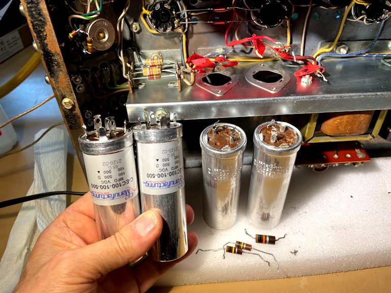
The kit, shown in this photo, includes four new can electrolytics,
plus eight smaller components used in the small voltage doubler board.

Of course, you could order equivalent parts on your own (see my
recapping article), but it's handy to
get custom cans that are drop-in replacements for the originals.
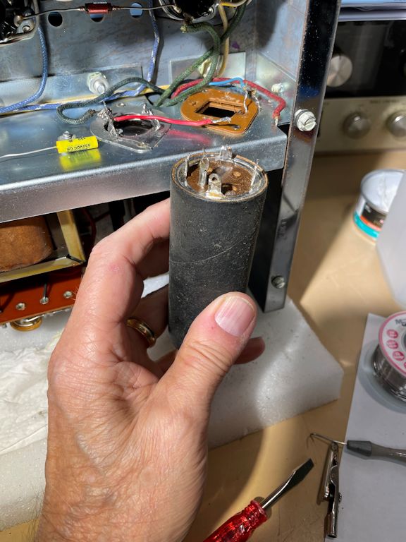
Let's start with this can, which contains a single 250-mfd capacitor rated for 275
volts:

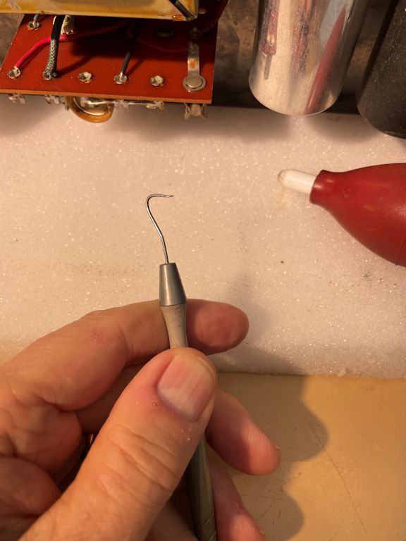
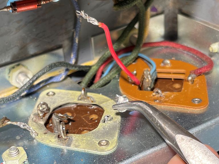
The first step is to unsolder and detach all the wires connected to the old
can, a job that's aided by two little tools: a dental pick with a curved point
and a solder sucker with a rubber bulb:
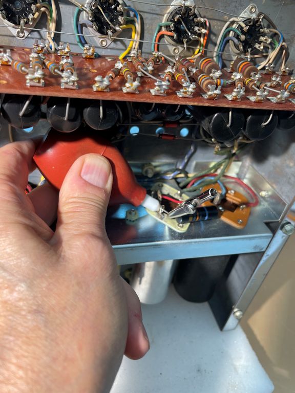
One by one, I detached the leads and set aside the parts, like the little red wire,
that can be reused. That striped bumblebee capacitor will be replaced.
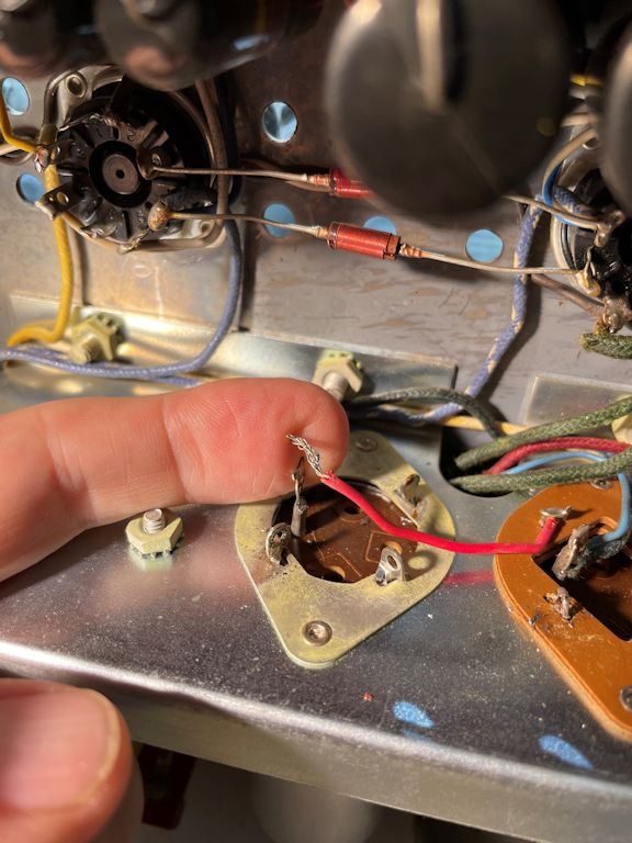
In this particular can, its metal case is electrically connected to the chassis.
The connection is made through metal mounting tabs that are twisted in their
slots to make a firm physical connection and then soldered directly to the chassis.
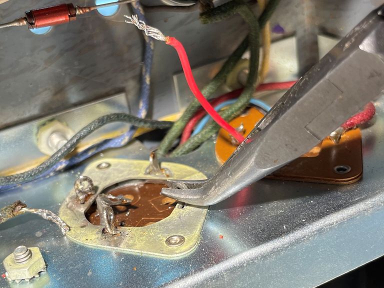
Using my solder sucker, I removed the solder from the mounting tabs.
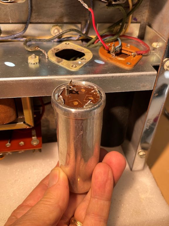
Then I twisted each tab back and forth until it broke off. The can will
pull out easily after the tabs are freed.


I removed the old can by drawing it downward and wiggling to release the old tab
stumps. The new can will slip right into the slots.
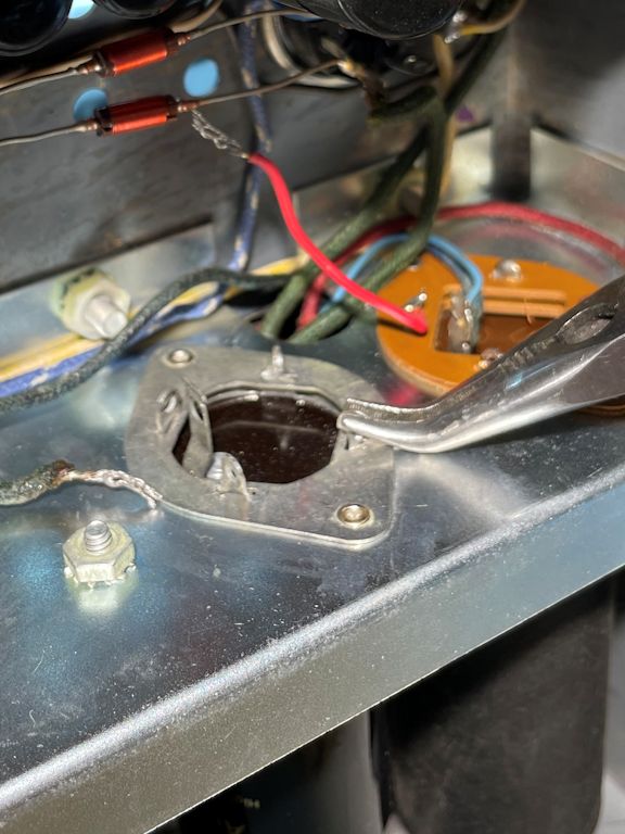
I wiped off some light oxidation from the can's mounting plate. Then, after inserting
the new capacitor's tabs in the slots, I could twist the tabs to secure the can in place.
You should twist each new tab about one-quarter turn, so that the tab lies
perpendicular to the slot.

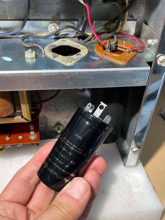
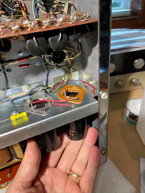
I'll follow the same process for the adjacent capacitor, but notice how it has a tan phenolic
insulating wafer to isolate the can from the chassis. The metal can will be at a potential different
than the chassis, so it is encased in a cardboard sleeve to prevent accidental shocks.

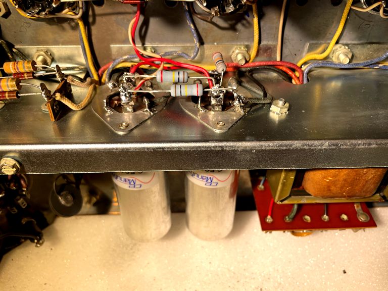
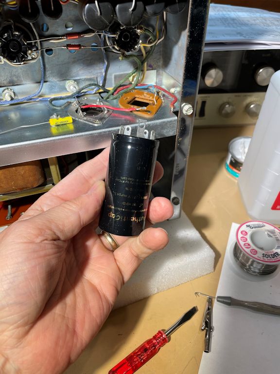
Before long, this pair of cans is wired up and ready to go.
(Minor note: the mounting tabs of the Authenticap brand capacitor were a bit
too short to stick up above the thicker phenolic insulator. I fixed
that by extending the tabs with small loops of wire sufficient to make
firm physical and electrical connections.)
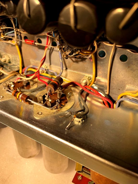
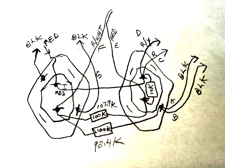
The second pair of cans is trickier, with more wires and components
to detach and reattach. I drew a little diagram and labeled the wires as I
disconnected each one.


The old resistors were close enough in tolerance (less than ±20%) to reuse,
but the installation looks neater with new parts and the replacements
cost only a few pennies.
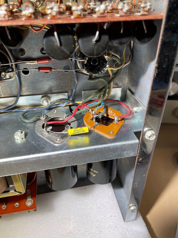
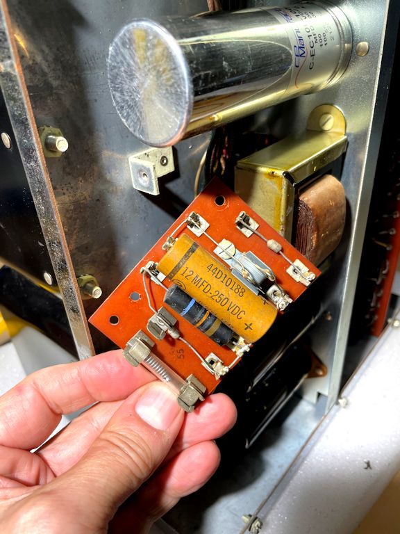
Rebuilding the Voltage Doubler
The voltage doubler circuit is mounted on a wee circuit board, as seen
earlier. I'll replace everything on the board except the fuse, using
parts supplied in the CTech rebuild kit.
You can rebuild this board without removing it completely. Loosen its
mounting screws, and there will be enough play in the leads to let you work on it.
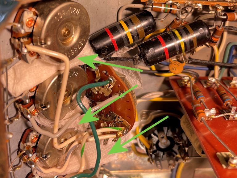
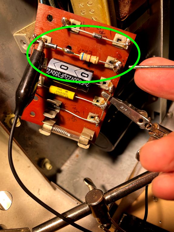
One component on the doubler board is a small selenium rectifier, circled below:

When you replace a selenium rectifier with a modern diode (standard practice), the
diode often has a lower "forward resistance" than the old unit, causing
a rise in the supply voltage. In that case, you add a dropping resistor
in series with the diode to bring the voltage back down to spec.
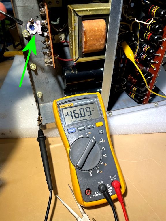
As directed in the rebuild kit, I tried different resistance values until
the bias voltage for my output tubes was -46 volts, as specified in the
McIntosh service manual.
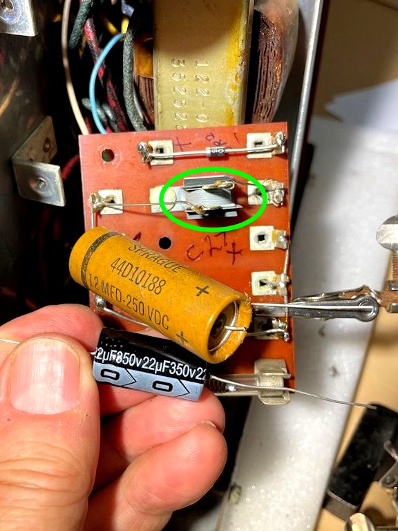
Finding the right resistor value was aided by
the use of a mini potentiometer (see green arrow) supplied with the CTech
kit. When you reach the desired voltage, you remove the mini pot and substitute
a permanent resistor of the same value. In my case, a dropping resistor of
680 ohms did the trick.
Setting the bias at the right voltage helps to extend the life of
your precious output tubes, so don't skip this step.
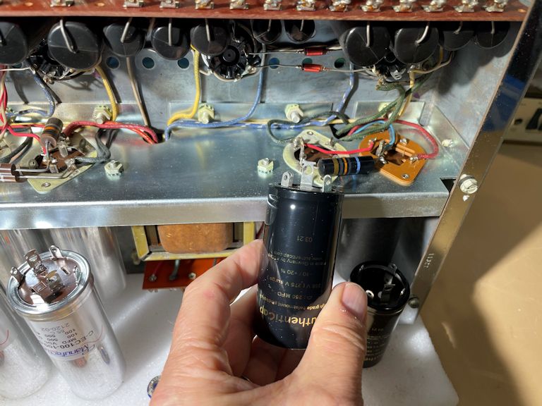
Replacing the Thermistor
The last step in rebuilding the power supply is to replace the thermistor, which
provides a "slow start" when you turn on the amp. In this photo, I'm
holding the old thermistor in front of its replacement.
The resistance of the thermistor drops as it heats up, within the first few seconds
after you switch on the amp. This moderates the sudden inrush of
current, helping to prolong the life of your tubes and other components.
Upgrading the MC240 Signal Path
After I finished the power-supply upgrade, I gave the amp a bench test,
checking voltages at a number of spots and comparing them to the service manual.
So far, so good! The power supply is healthy and the amp sounds sweet.
It should sound even better after I replace the old film capacitors in the signal path.
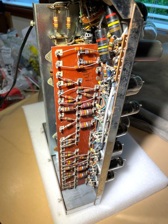
As we saw earlier, the MC240 has a long board with 16 capacitors on
one side and many (okay, 41) resistors on the other. I have seen MC240
restorations where that whole board was pulled out, stripped bare, and
repopulated with new caps and resistors and connecting wires. Before
going that far, I decided to take a closer look at the resistors, to
see if aging had made them drift beyond acceptable original values.
The resistors on that board were in better shape than I hoped.
On average, they were within about ±5% of the specified value, well within the
standard ±20% tolerance for new resistors. I decided to leave the resistors
alone and replace only the caps.
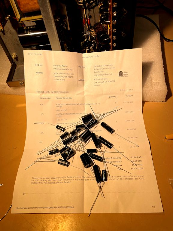
I'm not a believer in audiophoolery, but for once I spent a little extra money on
capacitors. Here are the JVX Premium caps that I ordered from JustRadios.
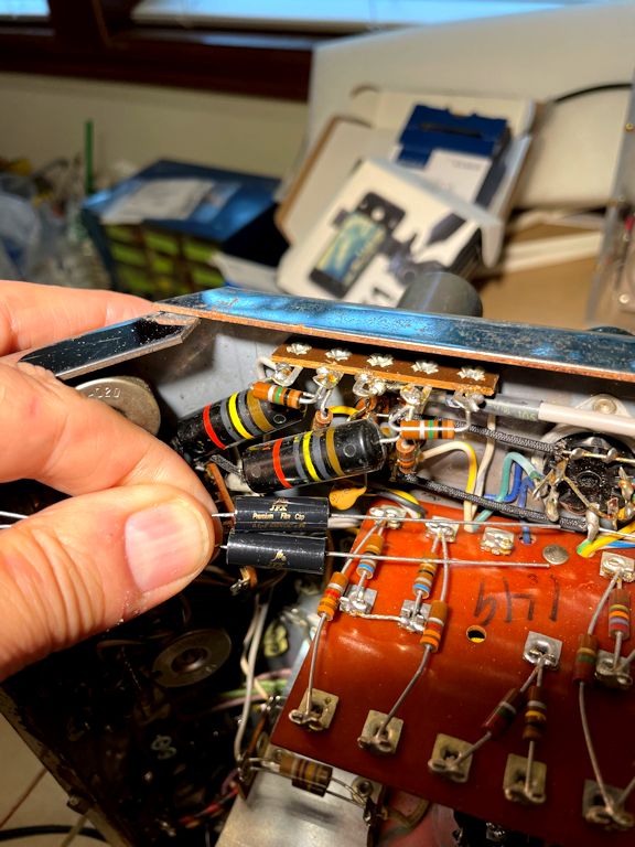
Replacing Coupling Caps C1 and C11
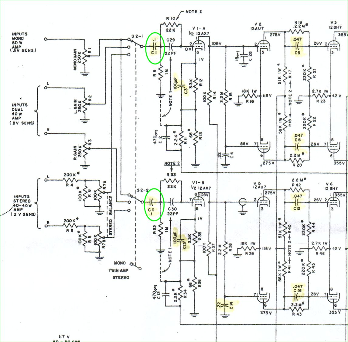
If you had to pick two components vital to the MC240 amplifier,
capacitors C1 and C11 would be good choices. They are coupling capacitors
that transfer the incoming audio signals to the
amplifying circuitry. Every sound this amp will ever make—every note, every chirp, every howl,
every fanfare—must pass through these two little parts. The following schematic
highlights C1 and C11.

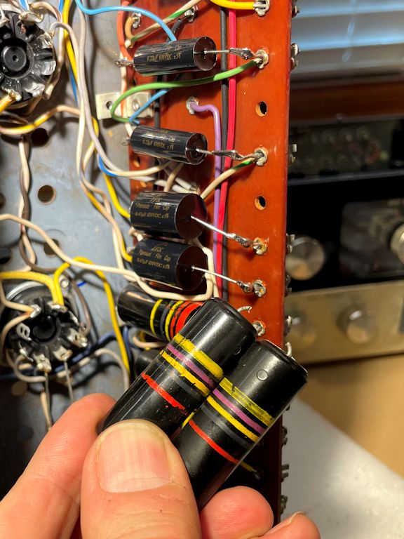
These two caps are mounted right behind the mode switch (part S2-1/S2-2) that passes
the signals to them. In this photo, I am holding two new replacement caps in front of
the striped bumblebee-style C1 and C11 caps.
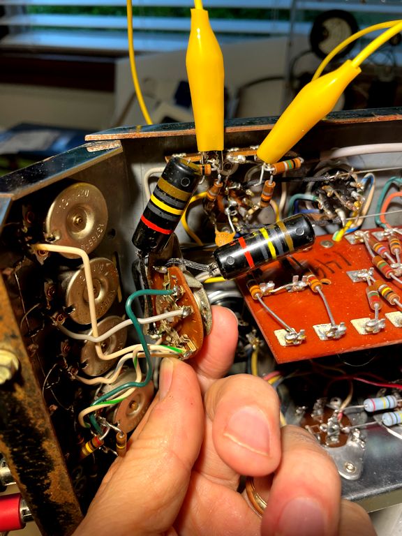
It will be easier to replace the caps if you remove two screws from the front of
the mode switch. This lets you nudge the switch assembly away from the inside
of the chassis, exposing the contacts where the caps connect.
The next photo shows the new caps (C1, C11) installed, with the mode switch back in place.
Recapping the Big Board
On to the big board! As seen earlier, the MC240 has a large phenolic board—about
a foot in length—holding a bunch of resistors on one side and 16 capacitors
on the other.
Although you could replace these caps by pulling the whole board from the
chassis, that's not needed unless you're also going to replace all the resistors.
Instead, as the following animation shows, you can remove this board's mounting
screws and get enough wiggle room to access everything on the capacitor side.

I'll start at the top of the board, where we find a pair of small electrolytic
capacitors (C3, C13) rated for 100 mfd at 3 volts. I'll replace them with new
100-mfd caps rated at 10 volts; the higher voltage rating does no harm.
Now I'll move down the board, replacing the old striped caps with my new
JVX Premiums. In this photo, I'm about one-third finished:
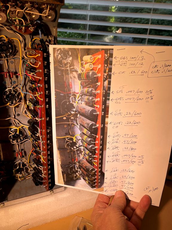
At last, the job was complete, and my little cheat sheet was finished, as well.
The cheat sheet used a photo of the original caps in place, and I wrote down
the values of the new caps as I installed them, one by one. My first version of
the sheet used part numbers from the Sams schematic; I later
added numbers from the McIntosh service manual.
When replacing parts en masse, it's prudent to make a record as you go,
in case you finish the job and find that you made a mistake. I normally take a digital photo
of every replacement and check it off on paper in at least two places (on
the schematic and the parts list). Not to mention any extra diagrams created along
the way, like my little sketch of the wiring around the electrolytic cans.
If you take on this restoration project, I advise you to make similar
records as you work. Another habit of mine is to turn on
the amp for a quick operational test between each replacement; if the
amp suddenly acts weird, that suggests you just made a wiring mistake!
At this stage, I gave my MC240 a nice, long bench test, and the results were
profoundly satisfying. My newly restored amp didn't just sound good—it sent
chills down my spine!
Cosmetics
Now, I can turn my attention to cosmetics. My amp, as you'll recall,
includes the ventilated tube cage (some MC240s were sold without cages).
The cage was in fine physical condition, but it
had a few minor scrapes, which I cured by spraying on a fresh
coat of heat-resistant matte black paint.
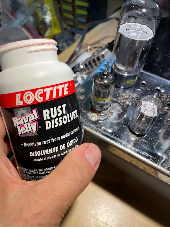
The chrome required more work. Underneath a layer of grime,
surface rust had developed.
Naval jelly to the rescue! This product contains phosphoric acid,
which is also used (in low concentrations) in Coca-Cola. I have
used naval jelly to remove rust from many old chassis, some of them in much worse shape
than this one.
The technique is simple. Dab some naval jelly onto the rusted area and let it
sit for a while. After the acid has worked, mild surface rust will
wipe away with a damp paper towel. If you still have some raised rust spots after
the first application, apply some more and repeat the process. Be patient.
In a few stubborn spots, I used the squared-off end of a wooden chopstick to gently
loosen remaining spots of surface rust. The idea is to nudge off the rusty bits without
scratching the mirror-bright chrome underneath. Don't use sandpaper or other
abrasives, which are too harsh for shiny chrome.
In the end, I wouldn't call my chrome perfect, but it passes the "six-foot
walk-by test," meaning that a casual observer likely won't notice defects unless you
point them out.
Final Thoughts
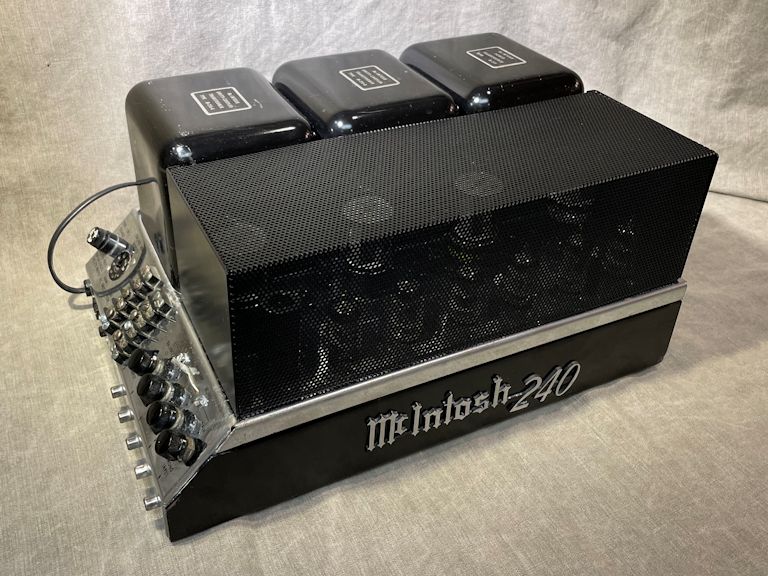
Here's my restored MC240 amp with and without its cage:
The amp looks more dramatic without the cage, but I appreciate having
the protection against mishaps.
You might expect this article to end with a rapturous description of
the MC240's high-fidelity sound, but I'll try to spare you too many superlatives.
Not only is my MC240 capable of sending chills down my spine, but I find that
I'm noticing new details when I listen to familiar old material. Bringing
fresh life to old music—what more could a guy ask?
This article tells only half the story of this double restoration project. You can
read the rest in my
McIntosh C22 preamplifier article.
Enjoy!
Phil
|