German Kleinempfaenger DKE 38 Radio (1938)
This Deutscher Kleinempfaenger (more properly spelled Kleinempfänger) DKE 38 radio was manufactured in
1938 in Germany.
The name means "German small radio."
The DKE in the model designation stands for the words Deutscher Kleinempfänger
and the 38 signifies the year of manufacture.
Using only two tubes, it's one of the simplest tube
radios that you will ever come across. The Kleinempfänger was designed to be simple, and therefore cheap,
so that as many Germans as possible could buy one. It cost only 35 Reichsmarks, roughly one
week's wages for an average worker of that day.
This was a propaganda radio, in short.
Germans nicknamed this set Goebbels' Schnauze (Goebbels'
snout), referring to the Minister of Public Enlightenment and Propaganda,
whose voice was often heard over the airwaves.
In the article about my Volksempfänger
VE 301 Dyn, you can learn more about German propaganda and the role that these
radios played.
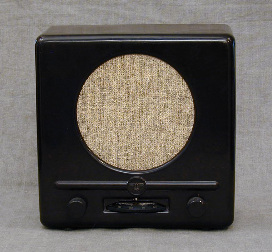
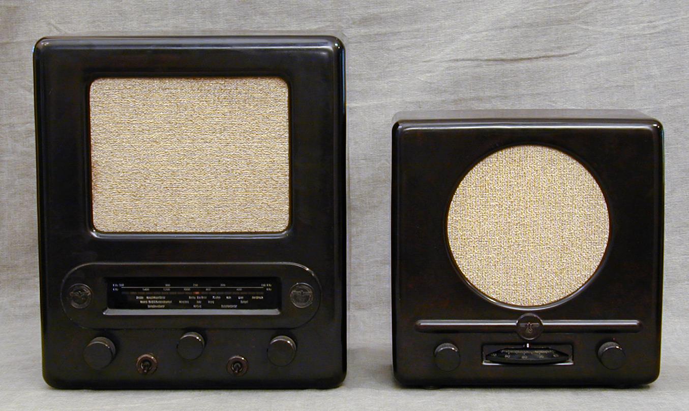
Front View
The appearance from the front is Spartan, a simple Bakelite box dominated by the
circular speaker grille. This is a small radio, measuring about 9.5 inches square
from the front, and only 4.5 inches deep.

The controls consist of two knobs and a tuning dial marked with
numeric scales from 0-100 in opposite directions. Directly above the dial you can see a tiny German
eagle over a swastika.
My radio is in excellent condition, with no chips or cracks in the cabinet, complete internals,
and a flawless grille cloth. The previous owner brought it from Germany to the US many years ago.
Modern radio users will find the Kleinempfänger's controls somewhat baffling. It receives two radio
bands, but with a single dial. As you rotate the Bakelite dial from extreme left to right, it displays one
range from 0 to 100, until you reach the middle, when it goes back down from 100 to 0.
This sort of dial was common in 1920s radios. Before radios had
frequency markings on the dial, the knobs had simple 0-100 scale markings. After discovering a
new station, the owner would write down in a log book the scale number that allowed him
to receive a broadcast at a given frequency.
The two knobs on the front are not what you'd expect, unless you are familiar with
old regenerative radios. One knob varies the degree of regeneration (feedback) in the receiving
circuit, while the other (I think!) adjusts to remove hum and other interference
to achieve the best sound. I will have to experiment with these after I restore
the radio, to discover how they work best.
Two Bands on One Tuner
But why would a radio tuning knob have scale marks going from 0 to 100, and then back down again from
100 to 0?
The Kleinempfänger is actually a two-band radio.
Using one half of the dial, it
receives MW frequencies. MW stands for Mittel-Welle, or medium wave,
almost identical to the American standard broadcast band (550-1600 kilohertz).
The other half of the dial receives LW, Lange-Welle, or longwave broadcasts.
Although no longer used for general broadcasting in the US, the LW band
remains in use throughout Europe.
The two halves of the tuning dial have different colored marks. When you pass from one band
to the other, an internal switch automatically selects the new frequency range.
Needless to say, the Kleinempfänger does not allow you to receive
shortwave broadcasts. The Nazis wanted Germans to listen to their
propaganda, not that of others!
It was actually a crime during those years
to listen to foreign radio, although a Kleinempfänger owner
with a long antenna and lots of patience might have been able to tune
in MW and LW broadcasts from neighboring countries, especially at night, when
radio waves propagate well.
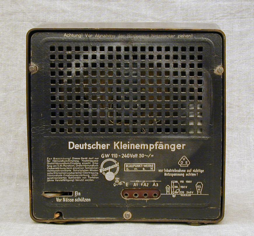
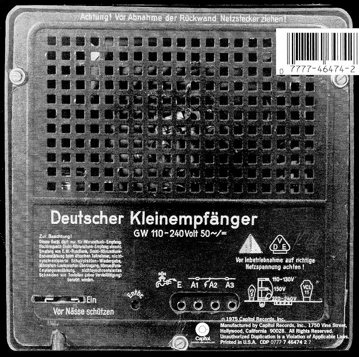
Rear View
Like other propaganda sets, the Kleinempfänger was built by more than two dozen German
radio makers, all using the same design. The back panel shows that mine was manufactured by
Blaupunkt, a manufacturer who is still alive and well.

The power switch for the radio is located on the back. It is a toothed metal
toggle switch protruding through a slot at the lower left.
Printed next to the switch is a warning: Ein Vor Nässe schützen! (Keep away from wetness!)
At the lower center, you can see connectors E, A1, A2, and A3. These are for the
ground (Erde, earth) wire and antennas of three different lengths.
The idea is that you would change among different antennas when changing
bands.
The back panel also shows us the number and type of tubes, along with the power options.
This radio uses two tubes. A type VY2 rectifier changes AC current into DC,
and a type VCL11 tube detects the radio signal and amplifies it for the speaker.
Designed for AC power, the Kleinempfänger allows you to select 110-130, 150,
or 220-240-volt current, as shown on the diagram. As with the larger Volksempfänger,
other models were available which could be powered with batteries or DC house current.
A warning at the top of the panel tells you to remove the power plug before
servicing the radio: Achtung! Vor Abnahme den Rückwand Netzstecker ziehen!
A warning on the right of the panel tells you to pay attention to the
AC line voltage before plugging in the radio:
Vor Inbetriebnahme auf richtige Netzspannung achten!
I'm not sure about the large paragraph at the left. It seems to say
something like, this device is to be used only to receive live
broadcasts, not to broadcast other "non-synchronized" material using a
record player or microphone and loudspeaker.
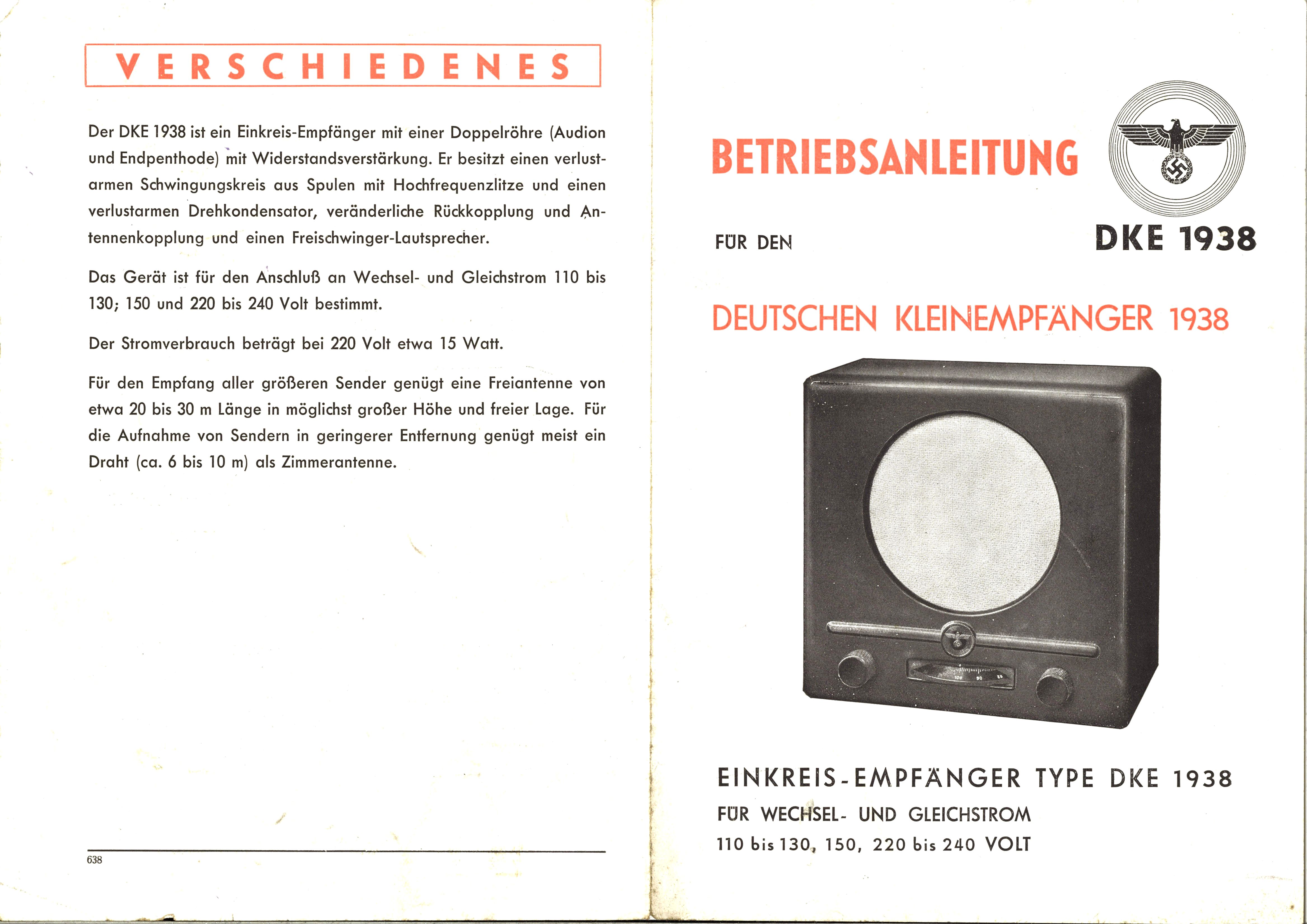
Operating Manual
Fellow collector Thorsten in Germany sent me the following Betriebsanleitung, or operating manual. The
manual was scanned at high resolution so that you can print it out for display next to
your Kleinempfaenger.
Loosely translated, the manual reads as follows:
The DKE 1938 is a single-circuit receiver with a double tube (Audion and pentode) with resistance amplification. It has a low-loss resonant circuit with a Litz-wire coil and low-loss variable capacitor, variable feedback and antenna coupling, and a cantilever speaker.
The device can be used with alternating or direct current at 110-130, 150, or 220-240 volts.
The power consumption is about 15 watts at 220 volts.
For best reception of all stations, use a large outdoor antenna about 20 to 30 meters long, strung as high
as possible. For receiving nearby stations, it is usually sufficient to use a wire about 6-10 meters long indoors.
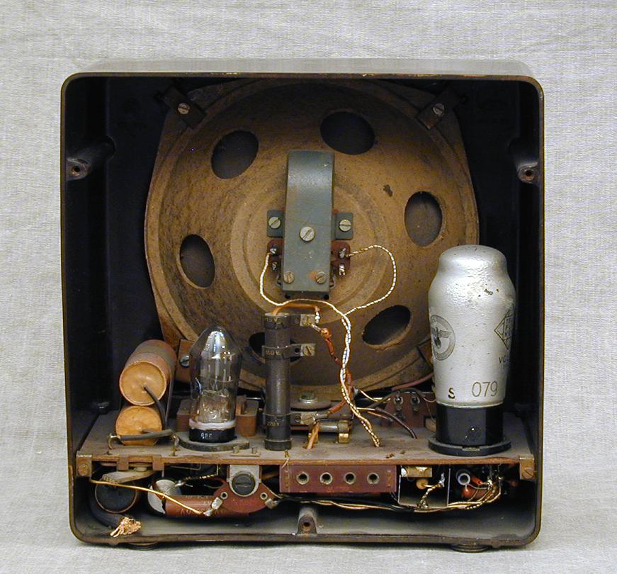
Interior
The next photo shows us the interior of this mysterious creature.

The small glass tube to the left is the VY2 rectifier and the larger silvery one to the
right is the VCL11. The silvery coating serves as a shield, cheaper than providing
a separate metal shield.
On the VCL11 shield coating you can see a Telefunken label and
other markings. This tube has the German eagle insignia. If you look
closely, you can see that someone scratched off the swastika that formerly appeared
in the circle under the bird.
Those familiar with US radios of this vintage will instantly notice differences.
Instead of a metal chassis, this radio is built on a big phenolic board,
a cost-saving measure which conserved scarce metal. The large electrolytic
capacitors to the left are encased in cardboard rather than metal.
A 1938 advertisement for this radio notes that extreme measures were taken
to conserve metal. Even the speaker frame was made of pressed composite rather than metal.
I suspect this material may be
similar to the "repwood" which forms the front panel of
my Emerson Snow White radio.
Made of wood flour compressed with a glue mixture, repwood is
actually more durable than one might expect.
The advertisement further states that the tubes are new types,
based on experience gained in the development of early VE 301 models.
Together, they consumed only 15 watts of electricity,
so the Kleinempfänger was inexpensive to operate, as well as to buy.
The radio employs a reed speaker, another economy because this type of
speaker requires no audio transformer.
We'll learn more about reed speakers later in this article and get a closer
view of the working mechanism.
Notice the big wirewound resistor standing upright at the center of the chassis.
The resistor is connected in series with the tube filaments, eliminating
the need for a costly power transformer.
To adjust for different line voltages, one moves a jumper wire from one
terminal of the big upright resistor to another. Mine is currently set
for 110-130 volts, with the jumper attached to the top terminal of
the resistor.
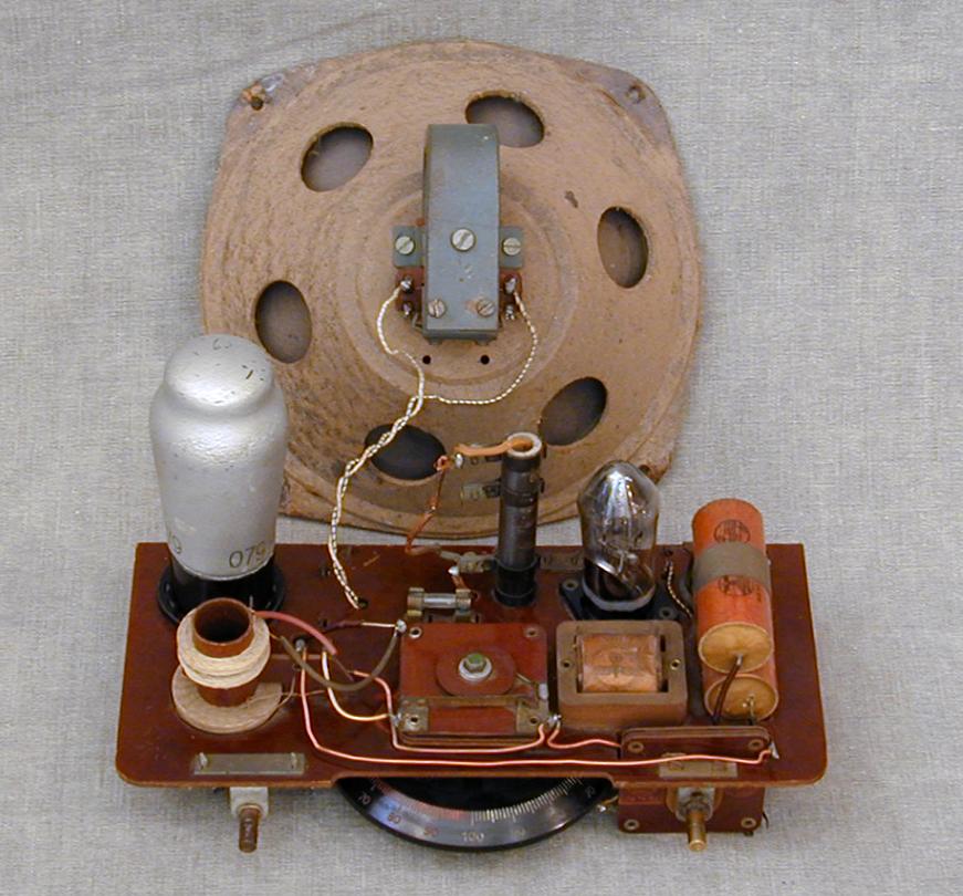
Chassis
Here is the chassis removed from the cabinet.

Removing the chassis is not difficult. After removing the screws from the back cover, you should remove the tiny
setscrews from the two front knobs, then gently pull the knobs off. If the knobs are frozen on their shafts,
put a few drops of penetrating oil on the screws and the knob shafts, turn the radio onto its face, and
wait overnight. Don't force the knobs too much if they don't come free after removing the setscrews. You don't
want to break the controls off the rather fragile phenolic chassis board.
After removing the knobs, you can turn the radio to its rear and remove the mounting screws for the chassis
and the speaker. You will need a long screwdriver with a thin blade to remove the speaker mounting screws.
The chassis will slide out from the back. If you bring out the speaker (as I did) without unsoldering its
wires, be careful not to break the connections.
After removing the chassis, I immediately put the mounting screws back where they came from,
an easy way to ensure that they won't be lost or mixed up.
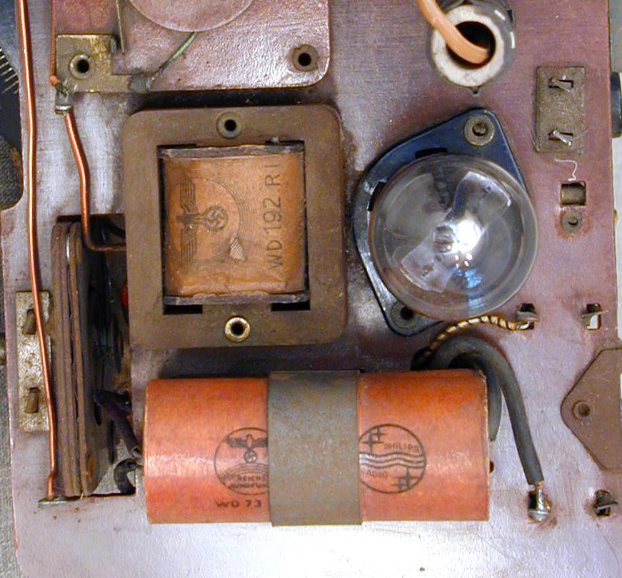
This view of the chassis shows how the tuning dial is color-coded, with
red markings for one frequency range and white markings for the other.
The two large capacitors at the right are filters for the power supply.
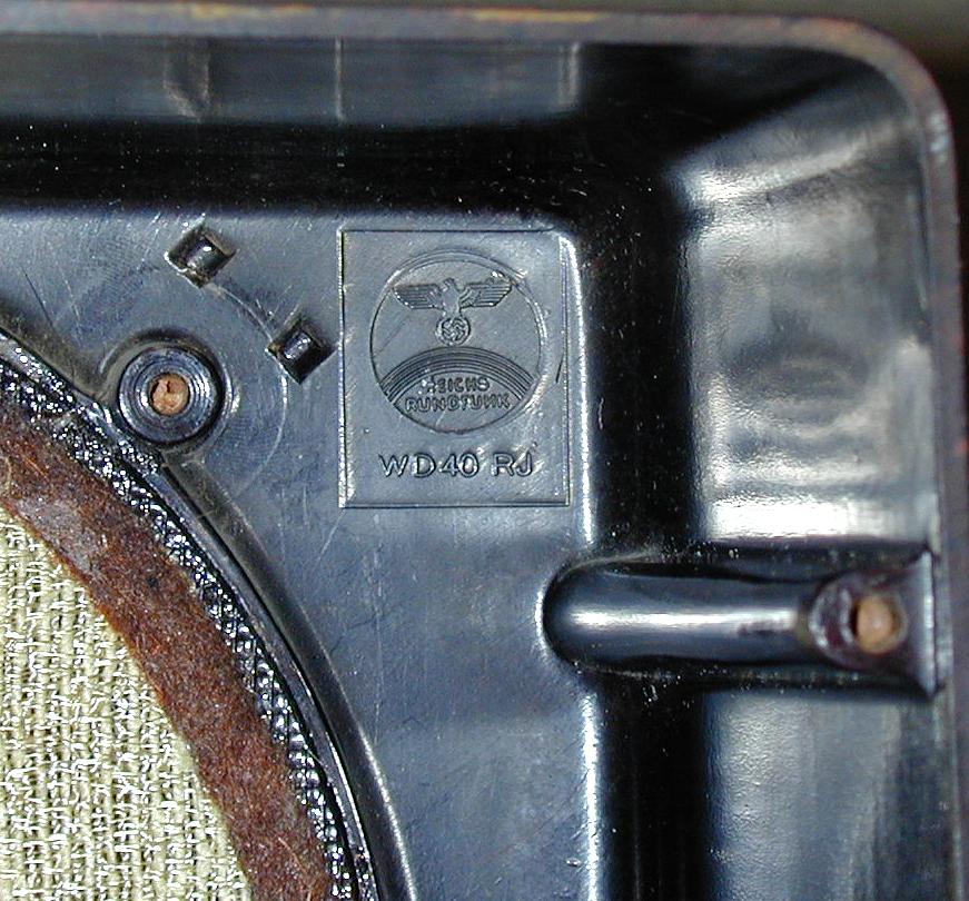
German war markings are visible on various components, including the cabinet interior.


The word Rundfunk seen on these components means "broadcast."
One of the capacitors bears the manufacturer name and logo for Philips,
the famous electronics maker from the Netherlands. Propaganda radios were sold in
German-occupied countries as well as Germany proper. Blaupunkt is a German manufacturer,
but I suppose that the factories obtained components wherever they could get them.
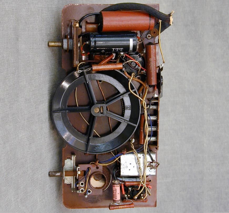
Under the Hood
A view under the chassis shows more about how the radio is constructed. At the center you can
see the round tuning wheel.

When I first examined this radio, I mistook the rectangular metal can at lower right
for the familiar IF (intermediate frequency) transformer found in so many other radios, but of
course, a TRF radio does not have IF amplifiers. The can shields the input circuit from radio
frequency interference.
To the right you can see four connectors, one for ground and the other three for antennas of different
lengths.
The black electrolytic capacitor near the top is a modern replacement. A fellow DKE 38 owner informed me that it is C9, a 0.9 mfd RF Filter.
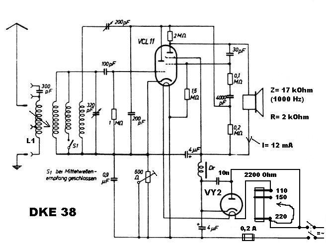
Here is the radio's schematic diagram.

It's interesting to puzzle out how this radio works
with so few components. At the left are the connections for antenna and ground, with three input jacks
for antennas of different lengths. The switch S1 alters the tuning circuit to receive either MW
or LW frequencies. Everyone will recognize the speaker at the right, of course.
The European drawing style used for the VCL11 and VY2 tubes differs slightly from American
conventions of the 1930s, but is still comprehensible. At lower right you can see
the power input and the big power resistor which allows you to adjust for 110, 150, or 220 volts.
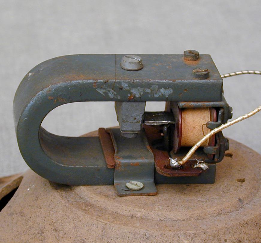
The next photo shows the business end of the Kleinempfänger's reed-type speaker, a design
which was becoming rather obsolete by the late 1930s.

This type of speaker was new to me. When I queried the rec.antiques.radio+phono newsgroup, I got
the following explanations of how they work.
They did not use the common today "voice coil" to drive the speaker's
cone or diaphragm, but had a flat piece of metal (a reed, I suppose) connected
by a mechanical link to the cone or diaphragm. This piece was mounted at one
end to the speaker's frame. The other end (the one connected to the cone) was
free to vibrate, just a few thousandths of an inch from the iron core of an
electromagnet driven by the radio's audio output stage. Sounded a bit like an
Edison cylindrical record phonograph.
From another contributor:
They were in common use in the UK for battery sets pre-war. They were
quite sensitive and did not need an output transformer due to their high
impedance and enabled a more compact form than was possible with a horn.
And another:
Phil, there is nothing wrong with a reed speaker. They were very common
in the 1920s. They can even sound quite nice, certainly much nicer than
horns of that period.  I think the big drawback was the limited volume.
They initially attempted to make them louder by increasing the cone size,
which could measure several feet in diameter.

Simply put, a dynamic speaker can out-"volume" and out-"bass" this type
of speaker.
Once I get this radio working, I guess I'll be able to judge for myself
how this type of speaker compares to newer designs.
Final Thoughts
I haven't yet done any electronic restoration of this set, and I certainly won't try to
power it up in its present condition. If I do restore it to a working state, I will
take pains to preserve as much of its authentic appearance as possible. Or, this might
be one of those radios which I leave completely untouched in the interest of
historical preservation.
Along with this set, I purchased its "big brother," a
model VE 301 Dyn Volksempfänger, or People's Radio.
The Volksempfänger article provides more of the history behind these interesting radios.
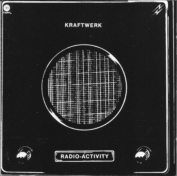
Finally, here's a question guaranteed to stump your opponents at the local trivia contest. What early electronic pop band used front and back
views of a Kleinempfänger DKE 38 radio for their album cover?


The answer is Kraftwerk, with their 1975 album Radio-Activity.
|