Heathkit Model FM-3 FM Radio Tuner (1957)


This Heathkit model FM-3 tuner matches my two other Heathkit hi-fi components, a
W-6M amplifier
and WA-P2 preamplifier.
Back in 1957, a hi-fi enthusiast might have bought these as a set,
but I acquired them separately: The W-6M amp in 2013, the WA-P2 preamp
in 2014, and the FM-3 tuner in 2018 when it popped up in a local craigslist ad.
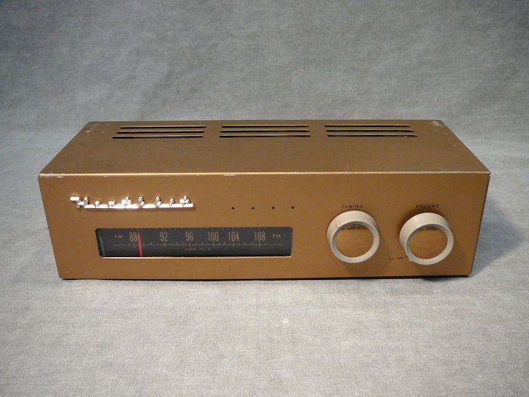
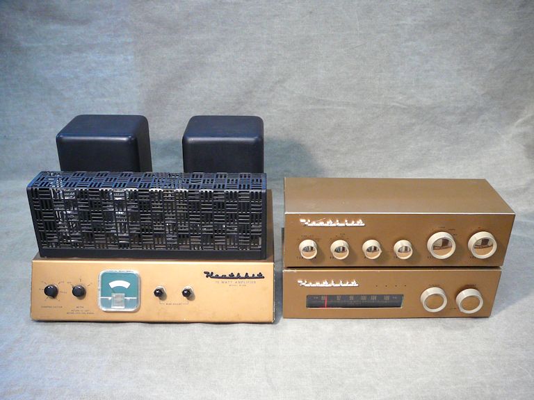
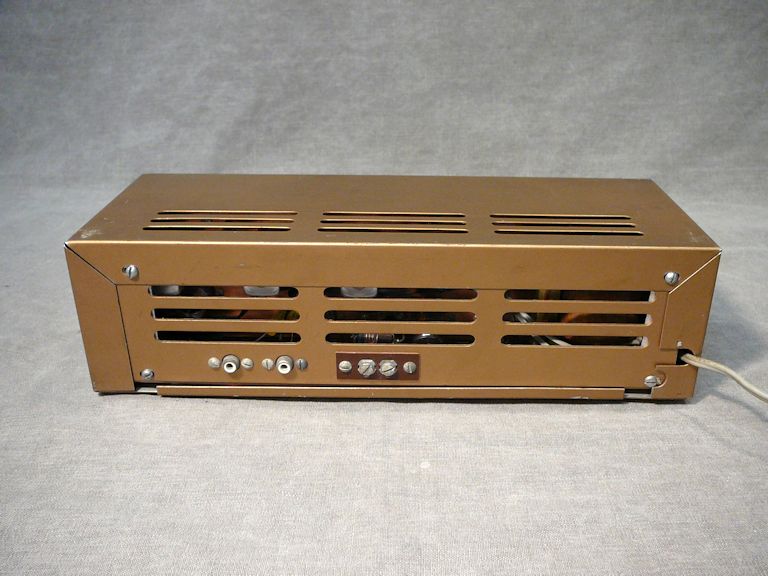
Here is my restored FM-3 tuner. The third photo shows it with my W-6M amp
and WA-P2 preamp:

Description
This 1957 High Fidelity ad shows the FM-3 tuner and WA-P2 preamp, as well as
Heathkit's model BC-1A broadband AM tuner:
The ad refers to the model FM-3A tuner, but mine is the original FM-3 version, which
sold for only about one year. The FM-3A tuner had some modest but welcome
improvements: better power-supply filtering, stronger AGC (automatic gain control) action,
an edge-lit tuning dial and a different tuner drive mechanism. Later in this article,
we'll see how I upgraded my FM-3 with a couple FM-3A features.
The FM-3 tuner uses seven tubes:
| Tube |
Type |
Function |
| A |
6X4 |
Rectifier |
| B |
6BQ7A |
RF Amplifier |
| C |
6U8 |
Mixer / Oscillator |
| D |
6CB6 |
1st IF Amplifier |
| E |
6CB6 |
2nd IF Amplifier |
| F |
6AL5 |
Ratio Detector |
| G |
6C4 |
Output Amplifier |
(Note: Heathkit manuals label the tubes with letters (A, B, etc.) rather than numbers (V1, etc.) as you
might see in a Sams or Riders schematic.)
Here is the FM-3 tuner schematic:

Although compact and lightweight, this tuner has "grown up" features,
including a power transformer and AGC (automatic gain control); and it uses the ratio detector method
of FM demodulation. The assembly manual includes a detailed, section-by-section description
of the tuner circuits:
First Look
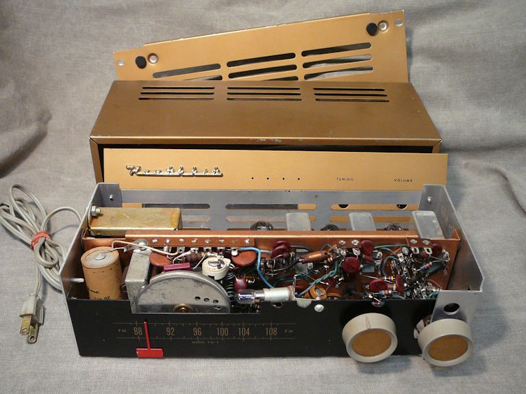
Here is my FM-3 tuner on the day when I bought it, with its covers removed:
At first glance, the tuner looked complete and quite clean. I cautiously powered
it up with a variac and wattmeter, looking for signs of
trouble. My little FM-3 sounded pretty good, although I didn't play it longer
than a couple of minutes.
Distinguishing FM-3 from FM-3A
Finding a correct FM-3 schematic took some doing. It was easy to find the later FM-3A Heathkit
manual, but FM-3 docs were nowhere to be found, even on eBay.
Eventually, I got a photocopied FM-3 manual from a member of the
Antique Radios Forum.
Another ARF member mentioned a 1957 Popular Electronics
article that described a Heathkit upgrade kit (model C-FM-3) for turning your FM-3 into a later-version FM-3A:
This article intrigued me. While I have my FM-3 on the workbench for basic service, maybe
I can upgrade it with FM-3A features, too! Unfortunately, that brief article didn't give
enough detail to do the upgrade. And, despite diligent searching, I couldn't
find a C-FM-3 upgrade manual anywhere.
When I compared the FM-3 and FM-3A schematics, the electronic changes looked straightforward. Here is the FM-3 schematic
notated to show what was changed and added in the FM-3A schematic:

Two of the changes mentioned in the previous article are evident.
From pin 2 of the first IF
transformer, a wire is rerouted from ground to the AGC line. The change should strengthen the
AGC effect, helping to even out volume changes when you tune from a weak station to a strong one.
A second change adds an RF filter (a .001mfd/1KV capacitor and a 100-ohm/1W resistor) at
pin 7, the output of the 6X4 rectifier tube.
A third change—not mentioned in the article—involves the 2-mfd/150-volt capacitor connected (through a 47K resistor) to
pin 5 of the 6C4 output tube. In the FM-3A, that capacitance is increased tenfold,
to 20 mfd; a 47K resistor is replaced with an 8.2K/1W resistor; and a connection to pin 1 of the
6U8 tube is rerouted.
Undocumented Mods
When I put the docs aside and examined my tuner, I discovered two modifications that don't appear
in either schematic (FM-3 or FM-3A).
The first mod was easy to understand. In both versions of the tuner, a 1K/2W resistor
is connected between the first and second filter capacitors in the power supply.
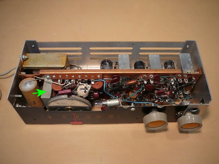
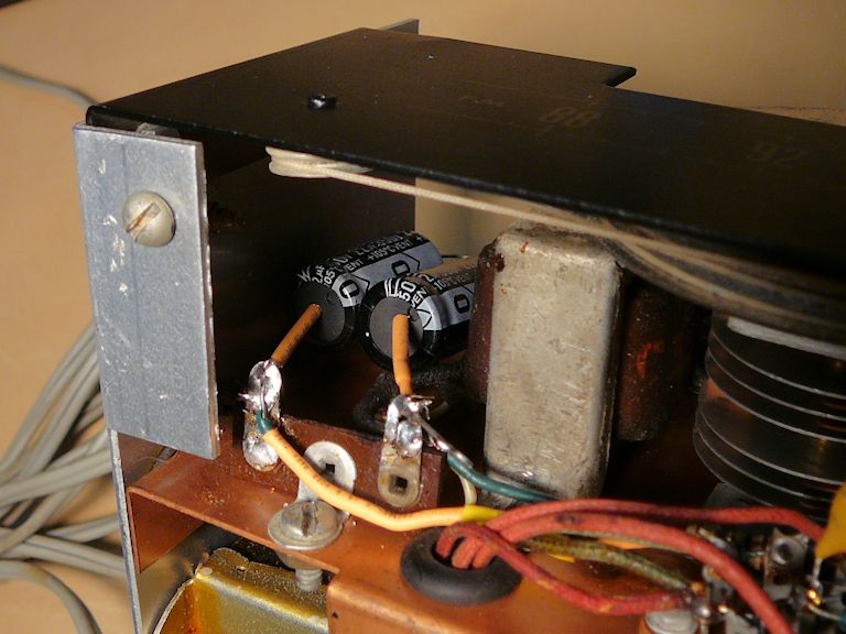
In my set, that resistor was replaced by a choke: a largish coil mounted in
an otherwise-empty space next to the filter caps:


In the words of the manual, that "1000-ohm resistor tends to help smooth the voltage because
it resists current variations in the filter circuit." Some power supply circuits use
a choke for this purpose; for instance, radios with an electrodynamic speaker can
employ the speaker's field coil as a filter choke. The previous owner of my FM-3 substituted
a more expensive choke for the original resistor, presumably to improve the filtering, so I'll leave it in place.
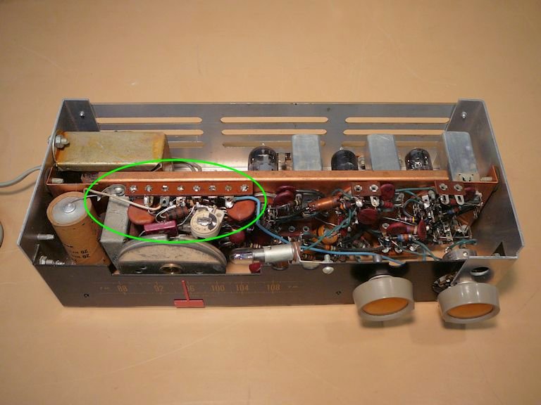
The second change was more dramatic. Mounted on the chassis above the tuning capacitor is
a mysterious eight-terminal strip containing a dozen components: resistors, fixed capacitors, and
a trimmer capacitor:

This module—whatever it is—doesn't appear in any schematic or drawing in
the Heathkit docs. In this FM-3A pictorial, I circled the area where the module would
appear in such a diagram; noticeably absent is any eight-terminal strip holding
a dozen components:

The construction of this network is extremely compact; its
components are wired on the "inside" side of the strip, and it's difficult
to even count them, much less read their values or trace their interconnections.
This schematic shows how the module is connected in my FM-3 with four wires:

Since one lead from the module connects to the antenna input and another connects
near the 6AL5 ratio detector, one ARF member opined that it's an AFC (automatic
frequency control) circuit. That's a reasonable guess, given that stability was an issue
with some of these tuners.
Since the tuner works with this module in place, I'll leave it alone for
now, and evaluate the tuner's performance after completing a basic restoration.
Checking and Replacing Tubes
One basic restoration task is to carefully
clean all the tube pins as well as their sockets. You'd be surprised how many problems
result from dodgy tube connections! Once a tube's pins are clean, it can be checked on a tube tester.
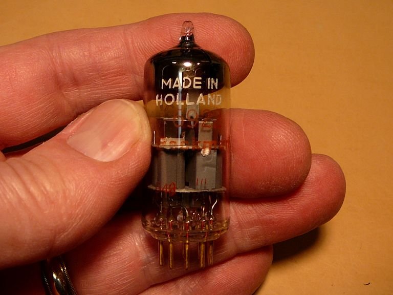
When I pulled the tube from the socket where I expected to find the 6BQ7A
RF amplifier, I found this type 6922 tube:

What's going on? My research showed that the 6922 is a premium ("instrument quality") substitute
for the 6BQ7A, with gold plated pins and other goodies—a pleasant surprise! The 6922
tube showed strong on my tester, so I put it in place and moved on to the others.
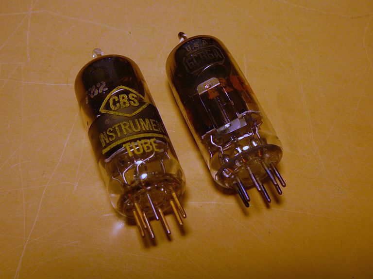
Some of the other tubes tested fine, but the two 6CB6 IF amp tubes were weak, so I ordered replacements.
When those arrived, I was surprised to find type 7322 tubes instead of the 6CB6s that I ordered. Like the 6922,
these 7732s are instrument-quality equivalents; the fellow who sold me the tubes substituted
these improved tubes at no extra cost:

Replacing Capacitors
While I continued searching for a C-FM-3 conversion manual, I proceeded to replace the old
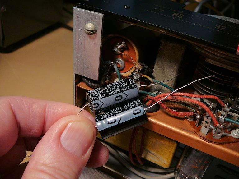
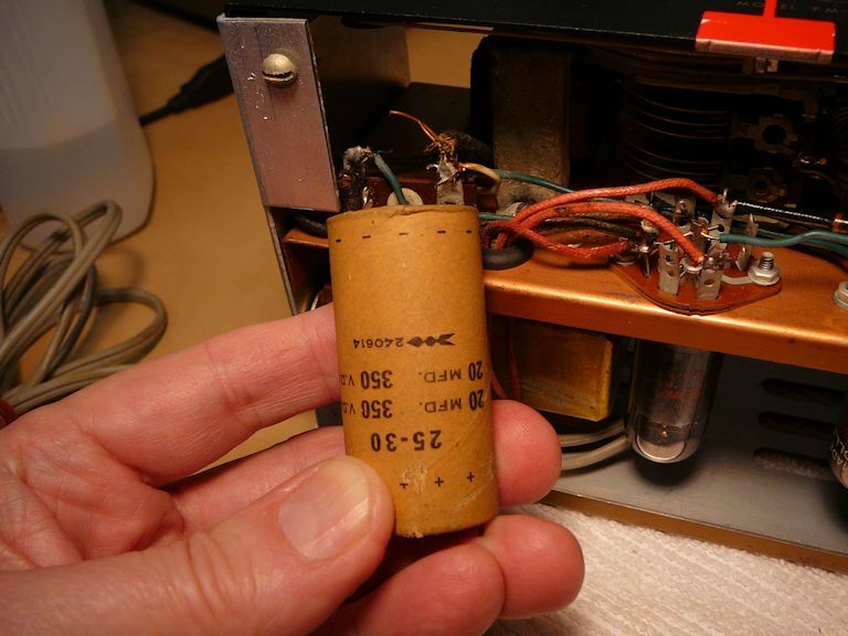
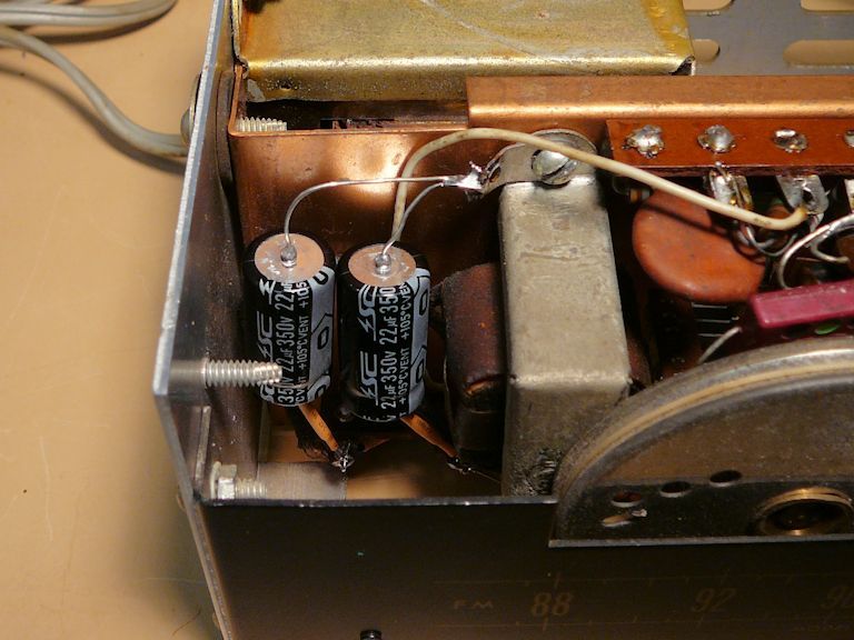
electrolytic and molded-paper capacitors, which need replacement no matter what. I started with the
dual unit containing two 20-mfd caps that serve as power supply filters.


In the last of those photos, notice that the negative leads of the capacitors are
connected to a terminal that screws into the chassis. As commonly seen in kits, the FM-3 uses
several ground terminals that use a mechanical screw connection rather than a soldered joint.
Faulty ground connections can cause problems, so while moving around the chassis
doing other work, I checked every ground connection with an ohmmeter and
made sure that its screw was tightly fastened.
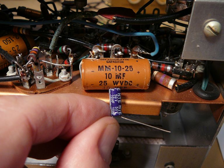
The next electrolytic capacitor forms part of the 6AL5 ratio detector circuit.
My FM-3 has a 10-mfd/25V cap here, although both schematics show a 50V cap
in that spot. I replaced it with a 50V-rated cap:


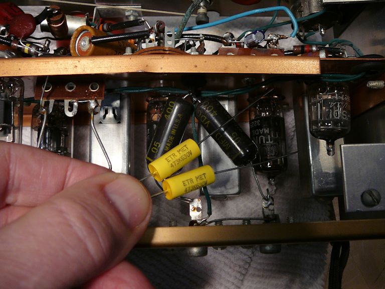
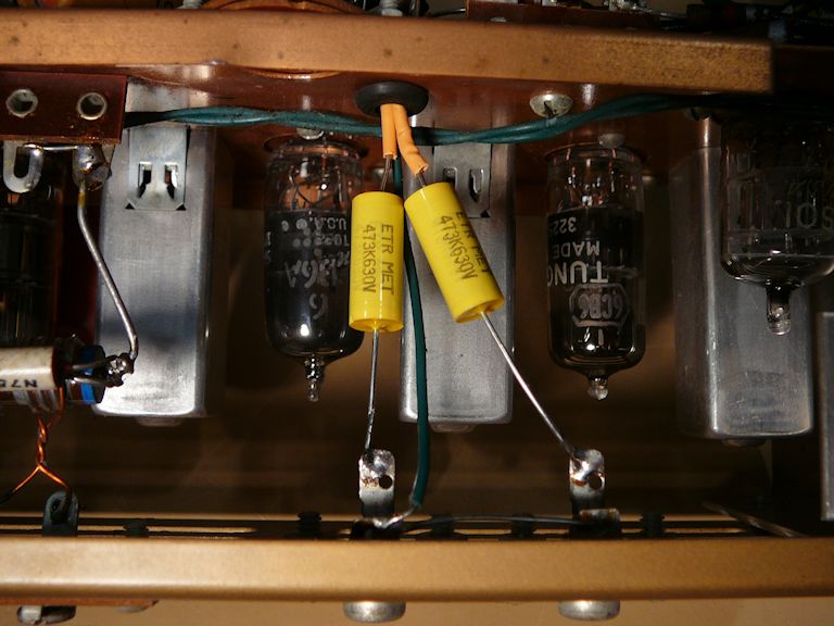
The FM-3 uses two .01-mfd molded-paper capacitors to couple the 6C4 tube's output
to the tuner's two audio output jacks. They are the chubby black cylinders in the following photo:

As noted in my recapping article, these are
paper capacitor in a plastic shell—unreliable parts that
should be replaced as a matter of course. The leads for these caps snake through a
hole in the chassis and must be insulated accordingly:


Perhaps you are wondering why the tuner has two audio outputs. If you examine the schematic
near the 6C4 output tube, you'll see that one fixed-level output comes directly from the ratio detector
circuit. The other output is amplified using the 6C4 tube and its level is adjusted using
the volume control.
This gives you a choice of outputs, depending on your amp/preamp setup.
In my case, since I own a WA-P2 preamp, I can connect the tuner's fixed-level
output to the preamp and then adjust the volume with the preamp's volume control.
If I didn't have a preamp, I could connect the tuner's variable output directly to the amp and
adjust volume with the tuner's volume control.
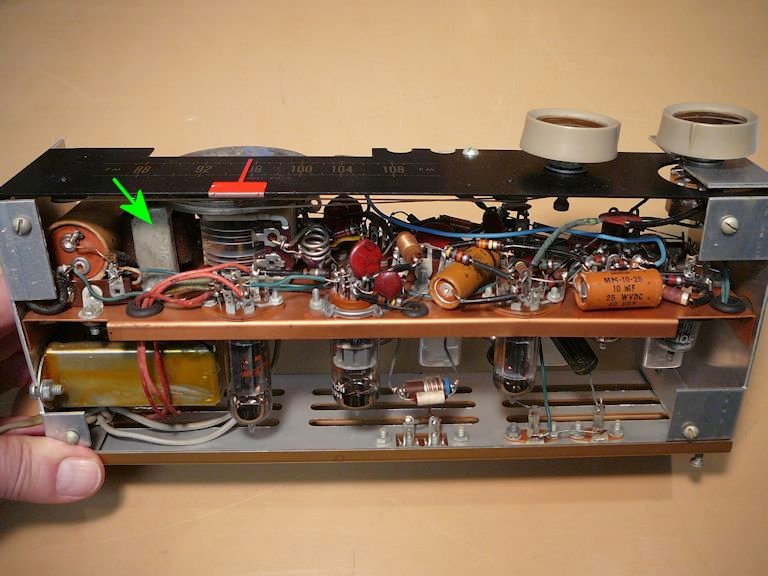
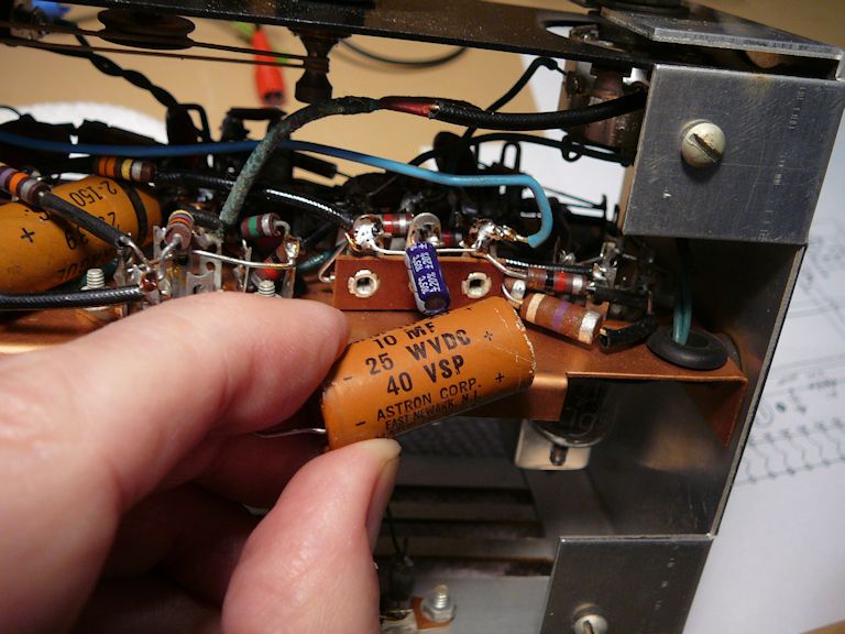
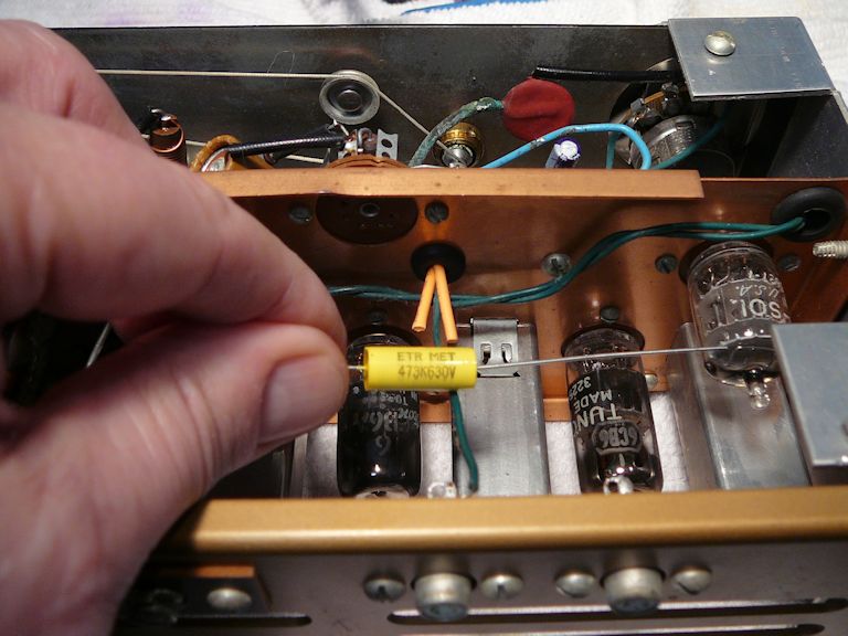
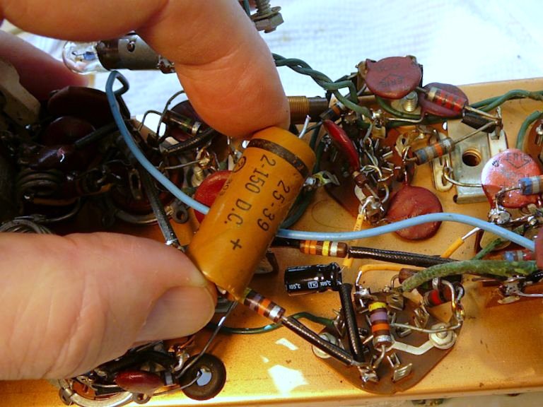
The final electrolytic is easier to replace if you first remove the FM-3's front
panel containing the tuner dial and drive mechanism. This capacitor was mentioned earlier; it
is a 2-mfd/150V component connected near the 6AL5 ratio detector:


As noted earlier, this capacitor is replaced with a 20-mfd electrolytic in the
FM-3A. For the time being, I decided not to change the cap's value. I'd like
to see how my FM-3 performs in the condition that I found it, except for
replacing the bad old caps with good ones.
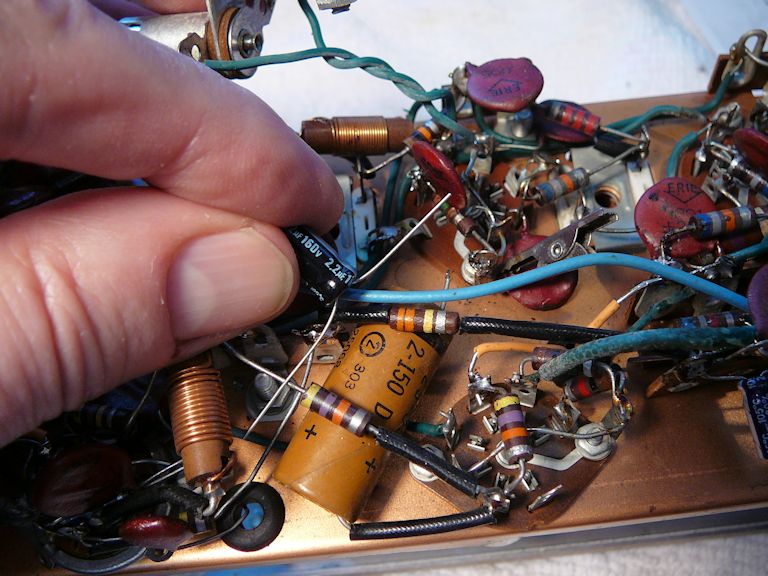
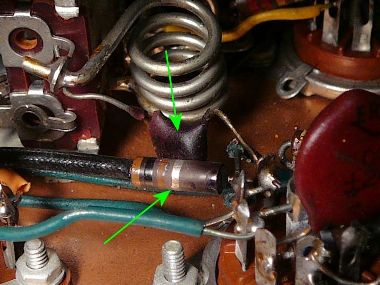
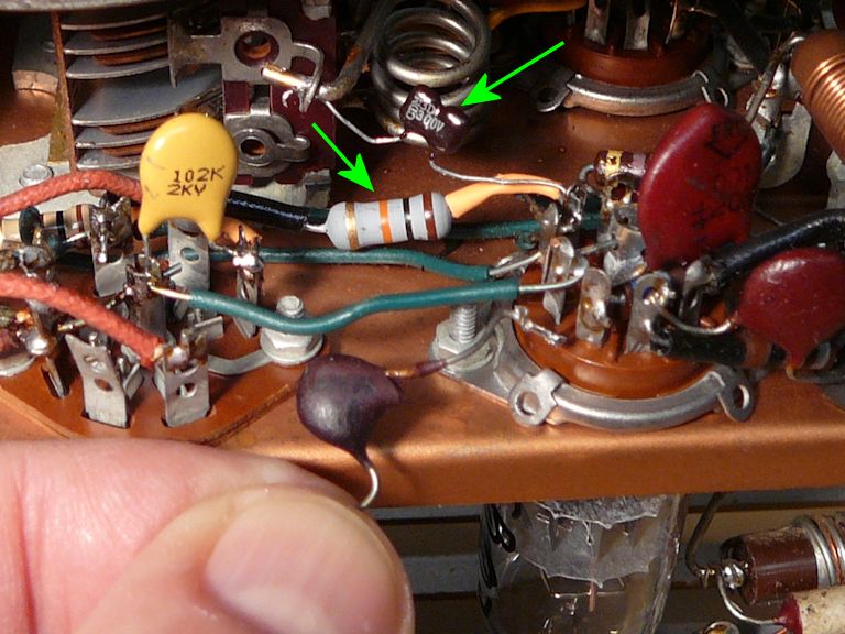
Replacing Two Burned Components
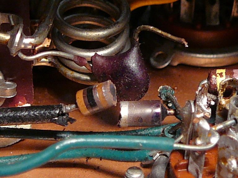
Sometimes a problem jumps out at you. These components (a 3.3-mfd ceramic capacitor and a 10K resistor)
connect to pin 6 of the 6BQ7A RF amp (tube B). They both look badly burned and the resistor
tested open:

When I loosened the solder joints, the resistor fell apart in two halves:
The next photo shows the two replacements; I'm holding the old burned ceramic cap for comparison.
The broken 10K resistor was upgraded from 1/2 watt to 1 watt for better reliability.

Shakedown Cruise
Now, the tuner was ready for a test, so I connected it to my other components:
the WA-P2 preamp and W-6M amp. The results were gratifying. It produced excellent audio, and
the tuning remained stable after an initial warmup period of a few minutes.
Adding FM-3A Features
By this juncture, I finally located a copy of the model C-FM-3 Conversion Manual,
part of which appears here:
The C-FM-3 conversion looked a little underwhelming. The kit did not include
"many capacitors and resistors" as stated in the article cited earlier.
And much of the manual involved the new tuner panel and drive mechanism, which I don't have.
Another section explained how to reduce tuner drift
by installing a trimmer capacitor and replacing a 10-mmfd ceramic capacitor with
a new type N750 cap. I guess the N750 has a more favorable temperature coefficient
than the original part. In any case, these changes involve the section where my
mystery module (apparently an AFC circuit) is installed, so I decided to
keep my module and ignore those more rudimentary changes.
The C-FM-3 manual did give a clear description of two other mods—strengthening
the AGC and reducing RF interference. (It was nice to see these spelled out, but I had
already deduced how to do them by comparing the FM-3 and FM-3A schematics.)
I made those two changes and gave the tuner an extended test. It still sounded good,
and the modified AGC worked somewhat better at moderating the volume differences between strong and
weak stations. Out of curiosity, I measured the AGC voltage and found a range from around zero (for
strong stations) to as much as -7 volts (on weak stations), comparable to what you'd find in many other AGC circuits.
I have the equipment and knowledge to align an FM set, and at this stage my next step would usually be
to align the tuner, but after listening for hours, I couldn't come up with any reason to mess
with alignment. If anything degrades in the future, I'll give that another look.
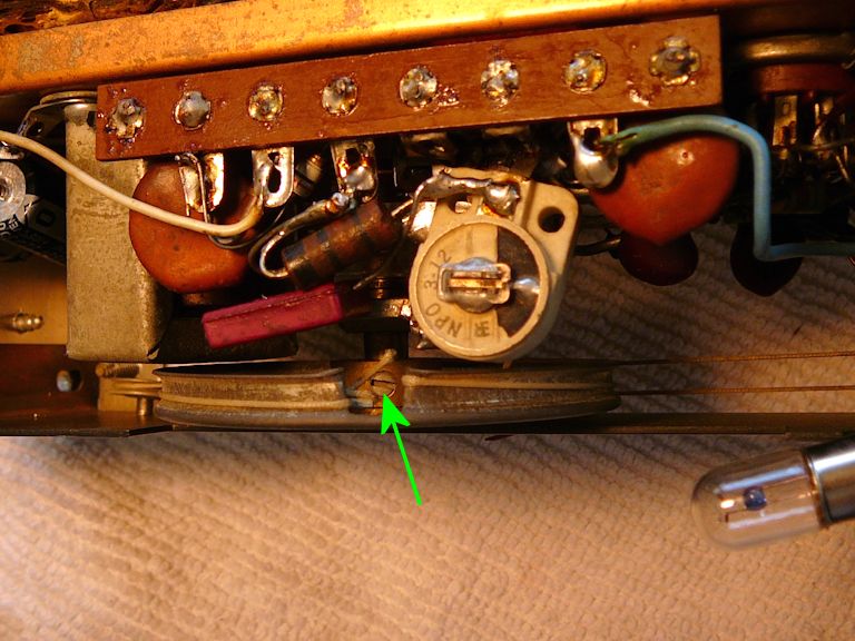
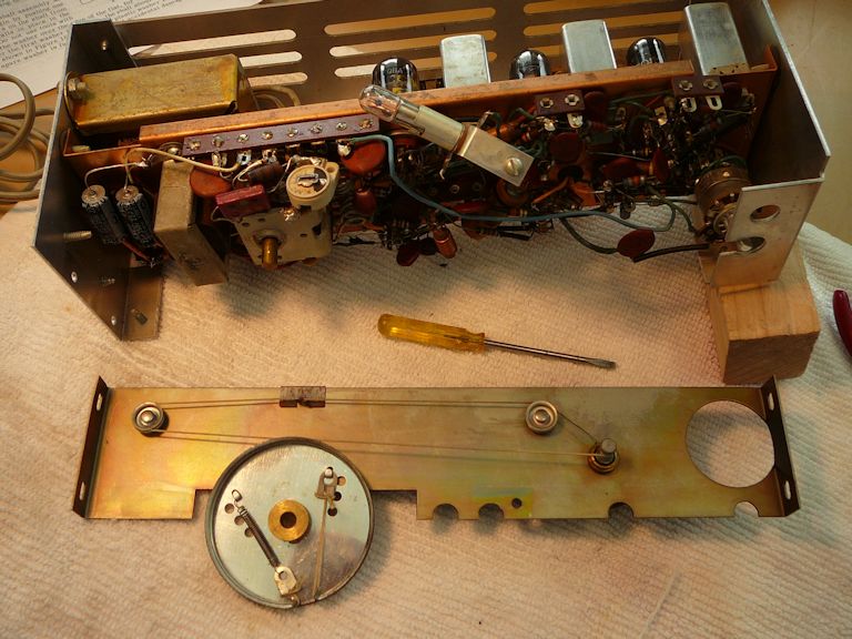
Restringing the Tuner
While reading the manual's dial installation section, I remembered that my tuner
worked backward. When you turned the knob clockwise, the tuner needle moved
downward (to lower frequencies) instead of upward to higher ones.
The manual has a nice stringing diagram, making this an easy fix.
I began by loosening the setscrew on the dial pulley's shaft; this allows the pulley
to slide frontward off the tuner shaft:

After detaching the pilot lamp bracket and removing screws on the ends, you can pull the whole panel. (Incidentally,
pulling that panel will make it easier to reach components when you are recapping, although
without the drive mechanism in place, you'll need to carefully move the tuner using
a plier or strong fingers when testing the tuner under power.)

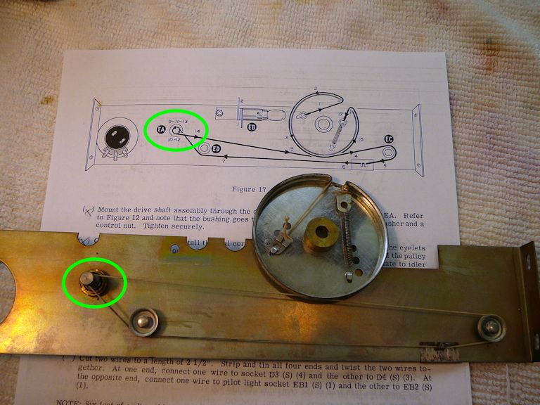
It's obvious what the original builder did wrong. The string going around the
tuner knob shaft (circled) must cross itself, otherwise that shaft will turn the wrong way:

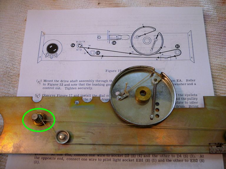
Here is the dial correctly strung; notice how the string crosses itself at the knob shaft:

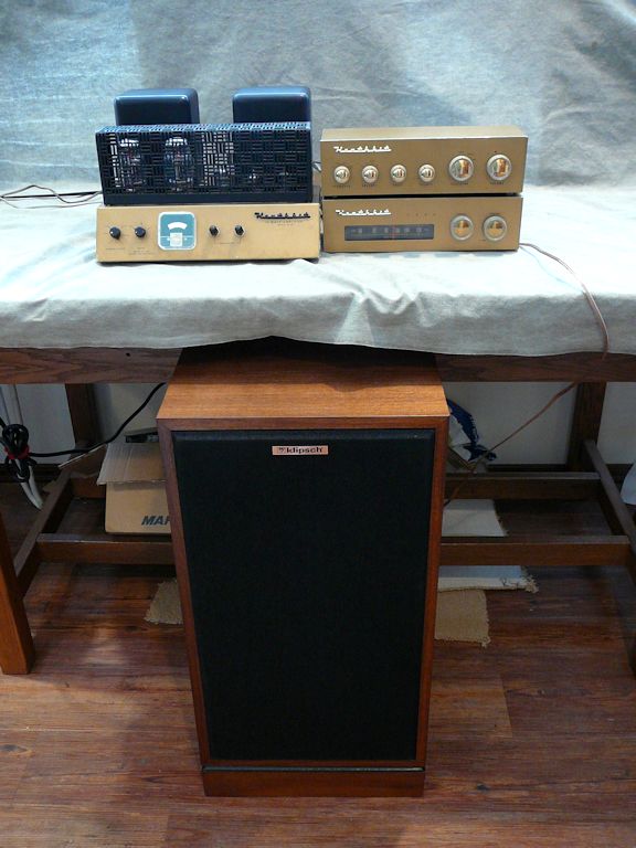
Final Checks
After further bench testing, I reassembled the tuner and gave it a nice, long trial
lasting the better part of the day, while I tended to other business in my shop. It
performed beautifully—especially when I connected the Heathkit system to one
of my "big daddy" Klipsch Quartet speakers:
Just for fun, I recorded a short musical piece off the air, featuring our local jazz station
KNKX. Click the icon to listen:

I originally got my W-6M to use with a vintage color TV monitor (see
RCA TM-10), but after hearing how glorious it sounds with
matching components, I may need to rethink that plan.
Final Thoughts
Overall, I'm pleasantly surprised by this tuner's performance. There's nothing exotic about its
design, but it delivers fine audio quality, with nice sensitivity and selectivity. Matched with
the right amp and speaker, its sound is rich and detailed—dead quiet in quieter passages
and undistorted at higher volume.
Are there better FM tuners out there? Of course. My McIntosh MR71 is a superior instrument,
but that's an unfair comparison. The Mac is nearly 10 years newer, with vastly more complex
circuitry, legendary build quality, and a price tag to match. Within its design constraints—a
modestly-priced tuner that an average Joe could build from a kit—the Heathkit FM-3
plays like a winner.
|