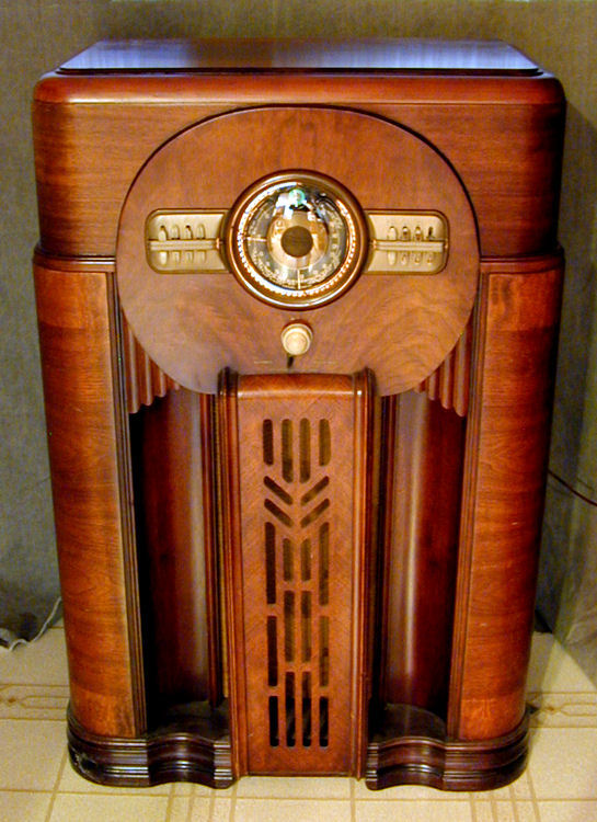
Zenith Model 12-S-471 Console Radio (1940)


With its sleek styling and black "robot" dial, this large Zenith 12-S-471 console
typifies a great design period in radio history. Put a high-performance 12-tube chassis
inside this luxurious cabinet and you have an unforgettable combination.
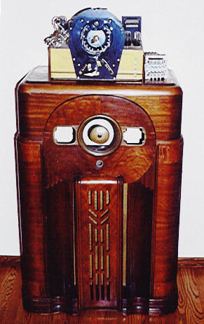
It took a fair amount of work to realize this radio's potential. The first picture shows the set on the day when I bought it.
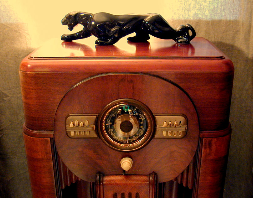
The second shows it after restoration.
Most of the cabinet was in decent shape, with small nicks and scratches here and
there. The top had some discoloration and flaking, probably from flowerpots.
In the first photo, the chassis had been removed and placed on top of the cabinet.
I don't always remove a radio's chassis for transport, but this set required careful treatment.
The chassis is mounted on springs, normally held in tension by large mounting
screws through the support shelf. Somebody had removed and lost the mounting screws,
allowing the chassis to bounce on its springs like a rocking horse! Had I not removed
the chassis, the dial might have smashed the dial glass by the time I got home.
The next photo shows the chassis as found, complete with a thick layer of vintage dust.

The owner said that the radio had played beautifully until one day he saw
"a lot of sparks in back." He quickly unplugged the radio and had not
tried it again. Looking at the rear, I saw that the power cord had frayed down
to bare wire where it entered the chassis, causing a short circuit.
Putting on a dour expression, I explained to the owner that virtually all 50-year
old radios require a thorough overhaul, and that a radio of this complexity might
take many hours to rebuild. I also pointed out various dents and scratches on the
cabinet, as well as a couple of chipped pushbuttons. By the time I was done,
the price had been cut in half! We made a deal and I brought my prize home.
Description
Model 12-S-471 ranked near the top of the Zenith product line in 1940.
Here is its description in a dealer's brochure:
Twelve-tube superheterodyne with Rotor Wavemagnet Aerial; Radiorgan;
Automatic Tuning; Television Sound connection; Triple Spectrum Robot Dial;
Outer Circle R.F. Circuit; 12-inch speaker; receives American, foreign broadcasts,
police, amateurs, aviation, ships. 42 inches high. Walnut finish. $119.95.
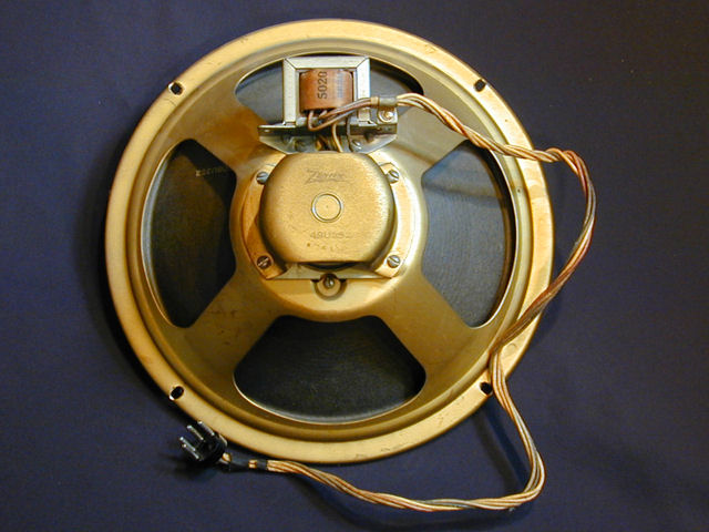
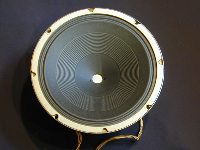
The next photos show the ample 12-inch speaker. Combined with two 6V6 tubes in
push-pull configuration, the 12-S-471 provides powerful, room-filling audio.

The Wavemagnet moniker was used for the antennas in many Zenith radios of the 1940s
and 1950s, including the TransOceanic. Although
WaveMagnets took many shapes, in this case it is a multi-element antenna mounted
in a box-like form with a fabric cover. You can rotate the antenna back and forth
to optimize reception from a particular direction. A slide switch on the antenna
lets you favor standard broadcast or shortwave reception.
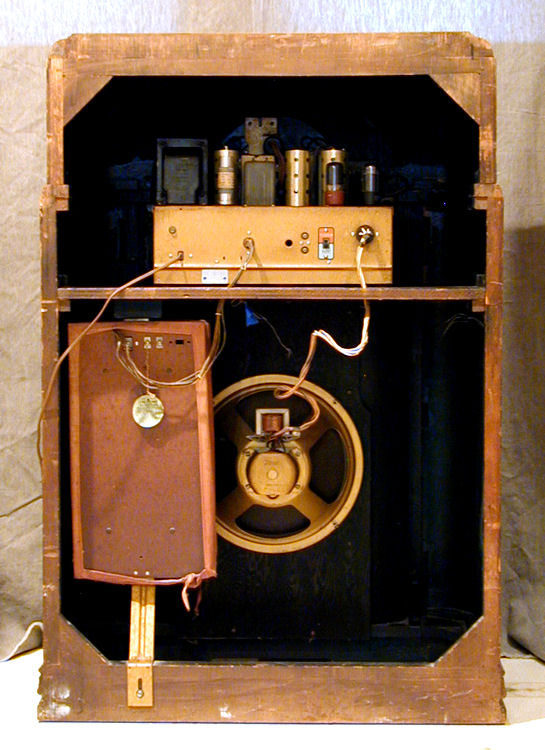
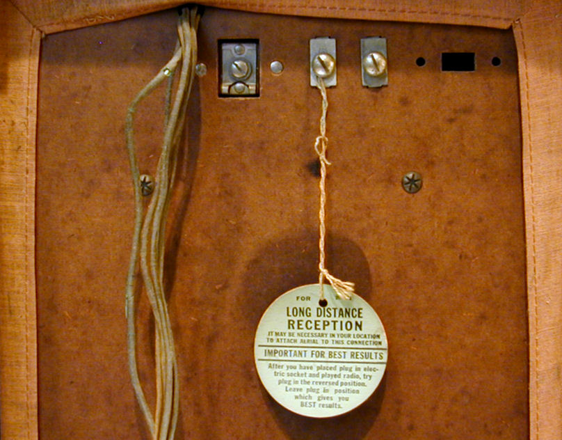
The Wavemagnet appears at lower left in the rear view:
Hanging from a terminal screw is a round green paper tag with instructions
for connecting an external antenna.
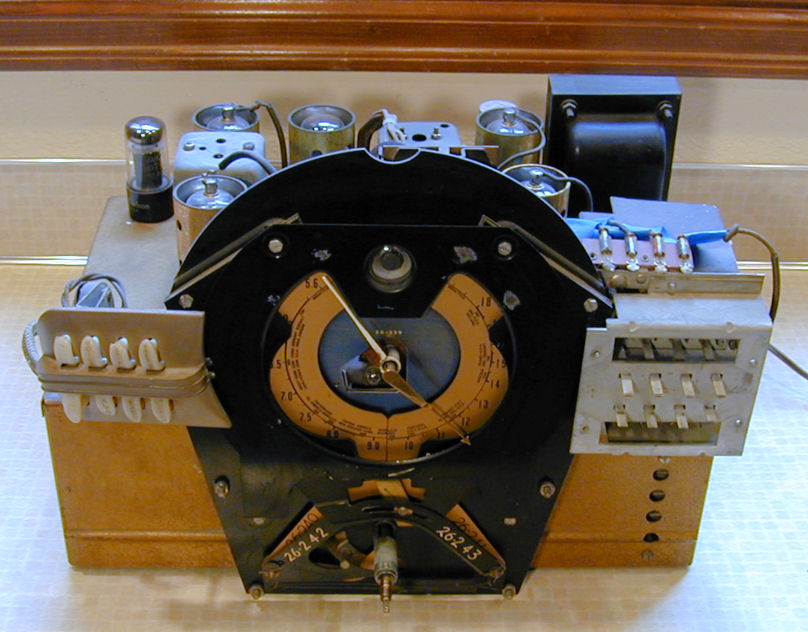
As the rear view shows, the chassis of this radio is unusually tall.
Zenith ads dubbed this the Super Goliath chassis, "generously
oversize . . . a promise of impressive performance. Beautiful hammered gold finish . . . spring floated in cabinet."
Even the tube shields were painted to match the hammered gold chassis color,
a feature shared by my Zenith 6-J-230 tombstone.
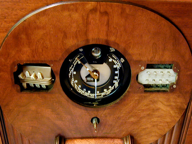
The next photo gives a closer view of the dial and pushbuttons. On the left are
the On and Off buttons, plus six tone buttons (Voice, Normal, Treble, Alto, Bass,
and Lo Bass). The automatic tuning buttons are on the right.
Radiorgan was Zenith's trade name for a group of tone control buttons.
Here is a breathless description from their sales literature:
Radiorgan brings new tone fidelity . . . new tone mastery . . . 64 tonal combinations!
Now, hand-in-hand with the mastery of time and space . . . the mastery of tone is yours
as well! Here is an organ keyboard that lets you choose high notes, brilliantly expressive,
and low notes, deep and sonorous, all in their proper proportion. You can press in
and pull out the "stops" of the Radiorgan keyboard to your heart's content.
You can obtain an endless variation of "acoustic symmetries!" You choose
them . . . with any kind of music . . . orchestra . . . string . . . brass . . . vocal . . . as you wish
. . . when you wish.
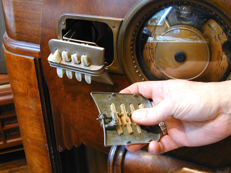
Automatic tuning was provided through a set of eight pushbuttons that could be set to
favorite stations. Pushbutton tuning was found in many other radios, such as my
Stewart-Warner tombstone. Zenith ads claimed that this company
was the first to introduce this feature, in 1928.
Zenith made their pushbuttons a bit easier to tune than did other companies. On
many radios, you need to adjust two components—a coil and a trimmer
capacitor—for each station. This radio has only one adjuster per station;
perhaps the coil and trimmer are ganged together on a single screw.
The Television Sound connector mentioned in the ad is a simple audio input jack
on the back of the chassis. Here is Zenith's description of the feature:
Your 1945 Radio Here Now! Television Sound Connection—which means you
can buy Zenith for the future with confidence. When television comes . . . you will be ready for it.
The TV Sound Connector was a hedge against obsolescence. Television broadcasting
was largely experimental before World War II, and affordable TVs were not
available until the late 1940s. A tiny number of prewar TVs were manufactured with no audio
section, to reduce their cost. You plugged them into a radio or phono amplifier to hear the sound.
For a few years, some manufacturers offered a Television connector for this purpose.
I suspect that very few of these connectors were used in practice. From the late 1940s onward,
TVs included their own audio amplifiers.
Had Zenith been able to predict the future, they would also have known that there would
be no such thing as a "1945 radio" for non-military customers. When the
United States entered World War II, all domestic radio manufacturing was diverted to war
production. The wartime moratorium was not lifted until 1946.
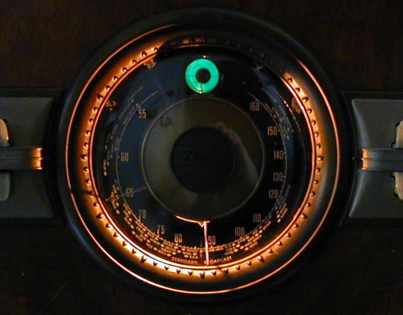
Collectors usually refer to the "Triple Spectrum Robot Dial" as a shutter dial or clamshell
dial. Zenith used the term "robot" for a few different dial types over the years,
and most robot dials did not use the shutter mechanism. Here is a description of
the 1940 dial from a Zenith brochure:
Robot Dial . . . the dial that is three dials! Extreme simplicity in tuning all
short wave and foreign broadcasts. Now all wave bands have separate, full sized dials.
Just one clear, easy-to-read dial is visible at a time. The lever automatically changes
the bands and pops up a complete new dial for each band.
This radio offers continuous coverage from .55 to 18 Mhz using three bands, labeled
Broadcast (.55-1.6 Mhz), Medium wave (1.7-5.6 Mhz), and Shortwave (5-18 Mhz). The
clever shutter dial employs three split dials, one for each band. The dials are
arranged in a stack with the broadcast dial in the frontmost position. Each dial
is a different color: black for the BC band, gold for shortwave, and a beautiful electric blue for medium wave.
Here's a view of the 12-S-471 dial set to the Broadcast band. You can also see the 6U5 magic eye
tuning indicator.
When you switch from Broadcast to Shortwave, the Broadcast dial opens like a shutter
in the middle and its halves disappear to the sides, exposing the Shortwave dial behind
it. When you switch to the Medium wave band, the second dial disappears and exposes the innermost third dial.
The shutter mechanism was ingenious but expensive to manufacture. After a year or two,
Zenith abandoned the shutters and went back to a single dial face, in which all bands are visible at all times.
Electronic Restoration
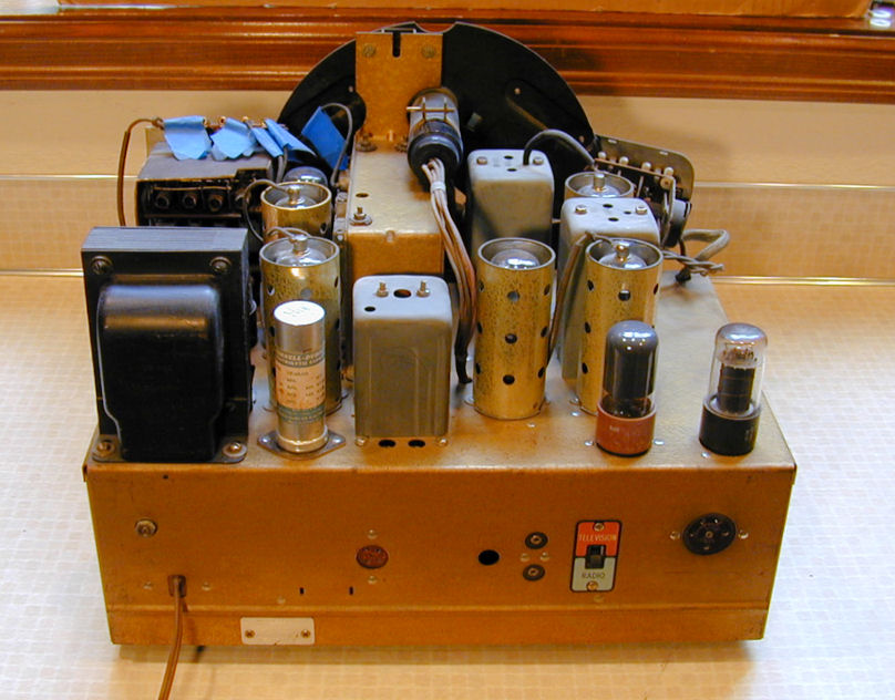
Below are two views of the 12-S-471 chassis after restoration. I put temporary blue tags on the
automatic tuner leads to avoid mixing them up.
My radio's electronics were complete and in pretty good condition.
The shorted power cord was responsible for the fireworks
seen by the previous owner. After replacing the cord and cleaning things up,
I slowly brought up the power on my variac. I was delighted to hear some local
stations loud and clear. I quickly powered down the set, not to restart it until
I had rebuilt the power supply.
Removing the chassis from the cabinet is a bit of a production. The
first step, of course, is to remove the two knobs and the bandswitch
lever, which are held on with setscrews.
The pushbutton bezels are held by small spring-loaded pins on
their inner sides. Push in the pin and slide the bezel slightly toward
the middle of the dial. The left assembly can be carefully turned and slid back
through its hole. The right bezel will come off completely.

After you remove both bezels, you need to remove eight tiny screws and then
take off the big dial bezel with its glass cover. That exposes mounting screws for the right
tuner pushbutton assembly. Once those have been removed, you can unscrew the
chassis mounting bolts from underneath and slide the chassis back and out.

Cleaning involved removing dust and grime from the chassis, using DeOxit
electronic cleaner on the controls, and lubricating moving parts such as the tuner
drive and band-changing mechanism.
All twelve tubes tested OK on my tester, but the two 6K7G tubes were
weak enough to warrant replacement. I ordered new ones through the mail along
with a copy of the schematic.
Zenith used this type 1207 chassis in five different cabinets, including the 12-S-471.
Here is a list of its tubes and their functions:
|
Tube |
Type |
Function |
|
V1 |
6K7G |
RF amplifier |
|
V2 |
6A8G |
Mixer |
|
V3 |
6J5G |
Oscillator |
|
V4 |
6K7G |
IF amplifier |
|
V5 |
6J5G |
Detector |
|
V6 |
6J5G |
First audio amplifier |
|
V7 |
6F8G |
Inverter |
|
V8 |
6V6GT |
Audio amplifier |
|
V9 |
6V6GT |
Audio amplifier |
|
V10 |
6U5 |
Magic eye tuning indicator |
|
V11 |
6X5 |
Rectifier |
|
V12 |
6X5 |
Rectifier |
In an era when "tube count" was equated with quality, manufacturers
occasionally used more tubes when fewer would do, especially in high-priced
consoles. This twelve-tube radio could have used eleven tubes, or even ten,
without degrading its performance. A single rectifier could have replaced the
pair of 6X5 tubes. One dual-function tube could have replaced the two 6J5Gs
that serve as detector and first audio amplifier.
Before diving into the electronics, I asked the
rec.antiques.radio+phono newsgroup whether
this model had any particular trouble spots. Among other advice, I
got this note from Ed Engelken:
Your radio is one of the Zeniths that uses a pair of 6X5 rectifier
tubes. Those tubes were famous for developing heater-to-cathode shorts.
When that happens, the power transformer is history. Don't ask how I
know this! The old-timers used to hook up a pair of #44 pilot bulbs in
series with the plate leads to the rectifier tubes to act as fuses.
This was supposed to work better (read faster) than fusing the power
transformer primary. Perhaps a separate small filament transformer
under the chassis feeding the 6X5's would be a good idea. Just don't
connect the heater circuit to ground - let it float.
Peter Bertini offered another perspective on the rectifier issue:
I have never used the #44 lamp trick, since a 6X5 failure has always
immediately blown the 1-amp line fuse I installed under chassis.
Of these three solutions—pilot lamps, transformer, or fuse—the
fuse was easiest. The parts cost a couple of bucks at Radio Shack and
took minutes to install. Adding a line fuse isn't a bad idea for all old radios,
in fact.
I replaced the old rubber tuner belt with inexpensive O-ring material,
a trick I had learned when restoring my Zenith 6-J-230.
I posted the following description of the process to the antique radio newsgroup.
From: Phil Nelson
Newsgroups: rec.antiques.radio+phono
Date: Sunday, May 16, 1999 7:38 AM
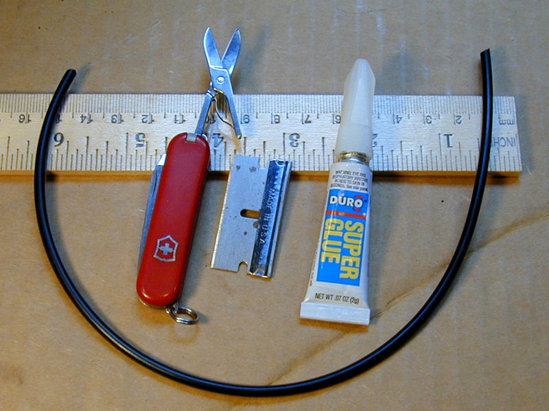
I couldn't find O-ring stock or a large enough O-ring, so I bought two
smaller rings. I cut both rings on the diagonal and super-glued two ends
together, forming a longer strip of O-ring that could be trimmed to length
after wrapping it around the pulleys.
I did not disassemble the tuning mechanism. All that it needed, apart from a
belt, was cleaning & lubrication. I did clean the pulley channels with
lacquer thinner and Q-tip swabs. The O-rings seemed to have something like
silicon lubricant on them, which I also cleaned off.
To snake the new belt down onto the pulleys, I used two 12-inch lengths of
solder as helping hands. Crimp one end of each solder wire onto each end of
your new belt. From the top of the chassis, you can send one helper down
each side of the top pulley, laying the belt's middle over that pulley. The
hands were especially helpful with my homebrew belt, which wanted to curl
back into its original form. (This was all done with the chassis on its
side, of course.)
Working from the bottom, I removed the helping hand from one end of the new
belt and laid that end just over the curl of the bottom pulley. Holding that
end in place with a finger, I stretched the other end down using the helping
hand. When the tension seemed right, I grabbed that end with a needle nose
pliers at just the spot where I wanted to cut it. Then I cut the belt on a
diagonal at the marked spot.
Holding both ends in one hand, I slipped the belt off of the top pulley to
give enough slack for gluing. One SMALL drop of super glue is all you need
to cement the belt ends. (Be careful not to glue your fingers to the belt!)
Then I slipped the belt over the bottom pulley and used one of the helping
hands as a crook to pull the far loop over the top pulley. As you get the
belt partway over the top pulley, turn the tuner knob slightly to run the
belt onto the pulley.
That's it! The new belt seems strong and secure. And I didn't have to pull
apart the whole tuning mechanism. It's not too hard to "feel" the right
tension when you're measuring the belt. You want it tight enough to grip the
pulleys but not so tight that you'll wear things out prematurely.
The next day, I began replacing capacitors. As always,
I started with the large electrolytic capacitors that filter the power supply,
then turned to the small paper capacitors.
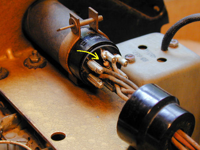
I also replaced the 1-megohm resistor for the 6U5 magic eye tube. If the
value of this resistor drifts upward, as often happens with age, the
eye becomes unresponsive. The tiny resistor is mounted inside the eye
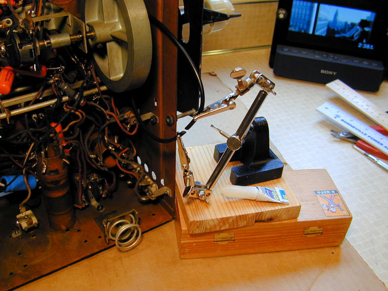
tube socket, wired between two pins. The next photo shows the new
resistor. I have loosened the socket cover and slid it down to expose
the resistor, nestled among the tube pins.
If you replace this resistor, be careful not to break the delicate wires or pin connectors.
I performed this surgery with the tube removed from its clamp and the pins secured
in a "helping hands" device on the workbench. Now the magic eye became bright and responsive.
The next photo shows the restored chassis after recapping. You can see most of the old components
that I replaced: about 20 capacitors and a few resistors that were significantly over tolerance.

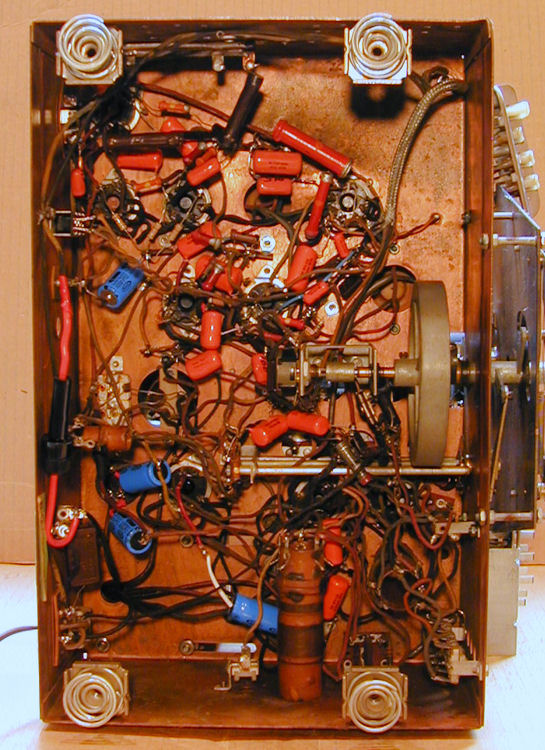
Here is a view of the restored underside. The small capacitors are orange
and the electrolytics are blue.
The next step was to align the radio using my signal generator and multimeter.
Now, the radio played like new, with outstanding sensitivity and
powerful audio. I was impressed with its shortwave reception using the onboard
Wavemagnet antenna. A well-designed antenna can deliver good performance in a small package.
I also adjusted the station pushbuttons, tuning each one to a local station.
Cabinet Restoration
The only bad part of the cabinet was the top, which had suffered some stains and flaking.
I had read about "re-flowing" a lacquer finish but never tried it. The idea is
simple: using a mild solvent, you dissolve the old finish and spread it around until it smoothly
coats the whole surface. That process was trickier than it sounded.
With a couple of phone calls, I located an auto paint supplier who sold lacquer
retarder by the quart. A retarder does what it sounds like, slowing the lacquer's drying action.
Retarder can be useful when spraying in humid conditions, to prevent the
"blush" caused when moisture is trapped under fast-drying lacquer.
If you mix retarder with lacquer thinner, then you have a mixture that will dissolve an old
finish, but keep it from drying too fast, so that you have time to smooth it around.
That's the theory, anyway . . . .
I wasn't sure what proportions to use, so I experimented on an old piece of junk furniture.
Different ratios of retarder and thinner certainly gave different results. With too much
retarder, my mixture did almost nothing except clean the surface. With too much thinner,
it acted more like a stripper, removing much of the old finish and color.
The next day, I tried reflowing the cabinet top. It worked pretty well, but the top ended
up lighter than before, so I masked the rest of the cabinet with tape and
plastic and then sprayed the top with Mohawk toner lacquer.
The rest of the cabinet had minor scuffs and scratches, which I concealed with walnut stain.
This process is easy and quick. Apply some stain to the scratch and let it set up for a minute,
then wipe it off briskly with a dry cloth. The stain darkens the blemish but doesn't change
the cabinet's overall color.
I let the cabinet dry overnight and then applied a few coats of clear lacquer to protect the
touched-up finish. In between each lacquer coat, I lightly buffed the whole cabinet with
#0000 steel wool and wiped it with a tack rag. The next photos show the result.
The grain of this veener is exceptionally pretty. Contrasting burled strips adorn the sides and the decorative
front piece uses alternating grained strips to accentuate the diagonal lines of the cutouts.
2011 Update
Fast forward to 2011, when I decided to take care of some minor items.
Installing the Zenith Dial Badge
When I got this radio in 1999, it was missing the decorative Zenith badge that covers the
center of the dial glass. Soon after that, I got the right part from a fellow collector,
and it sat in my desk drawer for about ten years.
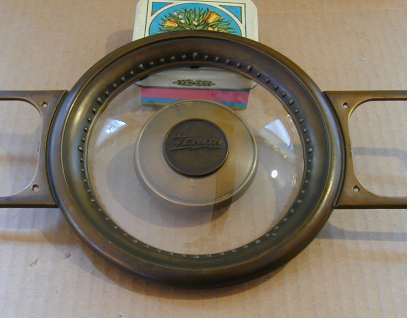
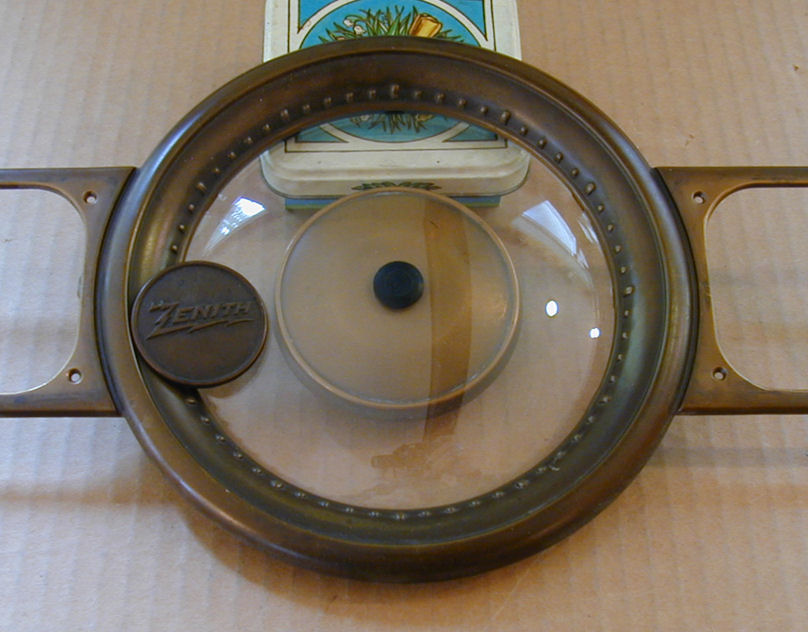
Ten years is long enough! The photos show my dial cover before and after installing the Zenith badge.
The brass disc inside the glass hides the switching mechanism and reflects
light from the pilot lamp across the dial. The previous owner had improvised a black plastic piece
to hold that disc on. I salvaged part of that piece to use as a collar around the screw that goes
through the dial glass.
Although these trim pieces are made of brass, notice that I did not shine them up.
When this radio was fresh from the factory, the trim pieces had a patina similar
to the color of the pushbutton bezels, which are painted. If you see a 1940 Zenith
with highly polished trim pieces, that's the work of an amateur who likes shiny trinkets more
than authenticity.
Replacing the Tuner Belt
The rubber O-ring tuner belt that I installed ten years earlier was holding up, but it had
developed some very fine surface cracks. Perhaps it would last another 30 or 40 years with
that appearance, but to avoid future trouble, I replaced it with a new belt.
If you're doing this for the first time, cleaning and lubrication is the first order
of business. Like some other Zenith tuners, this one has a spring that counters the weight of the tuning
capacitor as you move it to higher frequencies. The tuner should move freely when the belt is off and
your mechanism is properly cleaned and lubricated. If you turn it to a higher
frequency and then release it, the tuner will spin freely to the bottom of the dial
on its own. After the belt is installed, of course, the tuner will stay where you
put it.
I'll replace the belt with 1/8-inch O-ring stock, which my hardware store sells by the
inch. If you prefer to use flat material, that's available from
Great Northern in Minneapolis. Avoid using
square ring material, which tends to climb out of the pulleys.
An advantage of doing this a second time is that I could measure the old belt to get
the right length. I cut a 12-inch piece of O-ring material, angling the cuts slightly to provide more
gluing surface. Then I lightly rubbed the gloss off the new belt with very fine sandpaper to help it grip
the pulleys.

After cleaning the belt and the pulleys with isopropyl alcohol, I looped the
belt over the tuner shaft and glued it from below. For best results, buy a new
container of Super Glue. The helping-hands device isn't really
necessary, but it helped me avoid gluing my fingers together.

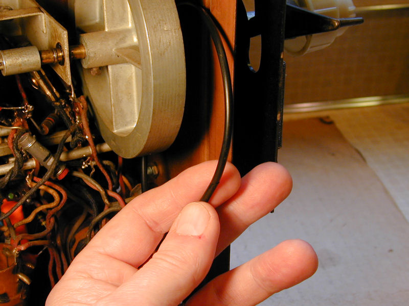
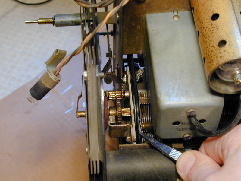
Lastly, working from above the tuner, I drew the belt upward and rolled it over the pulley while moving the tuner by hand.
My tweezer points to the installed belt. Don't forget to slide the pilot lamp back onto its mount after you're done.
Building a Solid State Replacement for a 6X5 Rectifier Tube
The old 6X5 rectifier tubes still worked OK, but I decided to make
a solid state replacement out of curiosity. I had seen this mentioned in an
Antique Radio forum.
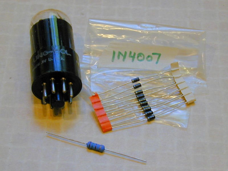
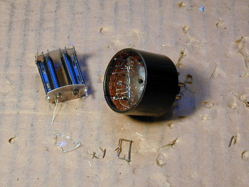
The solid-state rectifier is easy to build and costs only a dollar or two. The
parts that I used are a dud tube with an 8-pin base, two 1N4007 rectifier diodes,
and a 2-watt 150-ohm resistor. (You can adjust the resistor's value if you want
to match the original rectifier's output exactly.)
I wrapped the tube in a rag and broke the glass with a hammer, and then picked
the leftover glass bits from the base. I snipped off the tube elements, leaving
stubs long enough to solder onto. The type of tube is not important, as
long as it has internal elements connected to pins 3, 5 and 8. The first dud
that I found was a 12SN7, so that's what I used.

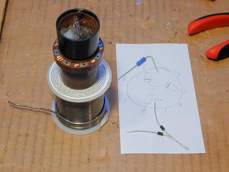
I plugged the base into an octal tube extender to hold it in place while soldering.
This also made it easy to identify the correct leads with an ohmmeter.
My sketch shows how to connect the 1N4007 diodes to pins 3 and 5 with
their cathode (striped) ends meeting at the resistor. The other end of the resistor
connects to pin 8. Here is the
internal wiring of a 6X5
tube's elements for reference.

Soldering the parts in place takes a minute or two.

The exposed joints in my new rectifier carry high voltage, so I cut the end from a
pill bottle and glued it over the top, adding a couple of ventilation holes for
the resistor, which creates some heat.
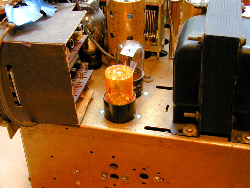
The next photo shows the solid state rectifier installed in my 12-S-471 chassis, next to
a conventional 6X5 tube.
If you want a more authentic appearance, you can cut the glass top from a dud 6X5 tube
and reuse that, as explained in this
discussion.
Since my 12-S-471 already has a fuse for protection, I'll put back the original 6X5 tube and
use my solid state sub when restoring other radios.
Curing an Intermittent Problem
At this stage, the radio sounded glorious, except for one small, intermittent problem.
Sometimes (but not always) when starting from cold, the audio would be faint and gargly
for the first two or three minutes. Then it would suddenly come back with normal
volume and fidelity.
When it occurred, the problem wasn't affected by turning the volume control, using the
tone controls or bandswitch, tapping the tubes, or nudging tubes around in their sockets.
Since I had spares on hand, I tried substituting most of the tubes (6K7G, 6A8G, 6J5G,
and 6V6G) with known-good ones. I had already tested all of the tubes and cleaned their
pins, but sometimes a tube will have a problem that a tester can't reveal. Subbing
those tubes made no difference.
I wouldn't call this a major problem. It didn't always happen, and it always cured itself
within minutes. The longer I worked on it, however, the more it bugged me. Eventually,
I broke down and ordered a new 6F8G inverter tube. The old 6F8G looked OK on my emission-type tube
tester, but it was the only tube that I hadn't tried substituting, and the inverter
would obviously affect audio volume and quality if it were flaky.
The new inverter tube cured the problem. Wahoo!
In hindsight, the time period when the problem occurred was a big clue. The first few minutes
of operation are the time when tubes are warming up fully. After that, the tubes
are as hot as they're going to get, but other components—resistors,
capacitors, transformers, etc.—take longer to heat up.
Logically, a problem that occurs only from a cold start-up and cures itself after a
few minutes is likely tube-related.
Incidentally, you can sometimes identify heat-related problems in resistors and capacitors using
freeze spray, but that's obviously not an option for tubes. A hot tube will pop if you shoot it
with coolant.
With that problem cured, I declared the project finished (for the second time!) and moved
the 12-S-471 to another room where it will get played more often.
Final Thoughts
This project was pretty typical for a Zenith console of this vintage. Recapping is standard,
and it's common to replace the tuner belt, too. I could have gotten by with less
cabinet work, but I wanted this set to be a showpiece in our home.
Now that I have rediscovered how great this 12-S-471 sounds, I intend to use it more frequently.
Perhaps one of these days I'll set it up next to my
12-A-58 and do a "Pepsi challenge"
listening comparison, just for fun.
Is this radio perfect? Of course not, and neither is any other 71-year old radio you're
likely to find. Although restored and ready for everyday use, it has some marks of age,
including a few chipped pushbuttons. In its current state, it plays like new and looks
like a well-cared for original, which is just how I like my vintage radios and TVs.
|