|

Build an AM Radio Transmitter
Have you ever wanted to listen to modern music or old-time radio
broadcasts on your vintage radio? Now you can!
Phil's Old Radios presents the Li'l 7,
a high-quality AM broadcast transmitter that you can build at
home for less than $50. It can broadcast
anywhere on the normal AM radio band and it accepts ordinary audio
input. Just plug in your CD player or iPod,
fire up the Li'l 7, and hear your favorite music playing
on an antique radio anywhere in your house.
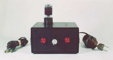
Here's a
picture of Li'l 7 as built by Phil.
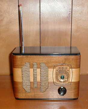
Douglas Herigstad made a more decorative enclosure for his Li'l 7,
recycling an empty cabinet from a 1936 Canadian Viking radio.
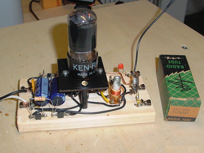
Still another approach is seen in this Li'l 7 built by Volker in
Italy. He used old-school techniques, building
the transmitter on a wooden breadboard with open wiring.
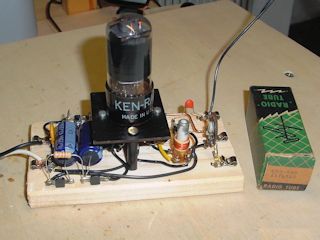
You can read more about Volker's version at the end of this article.
The Li'l 7 was designed by fellow radio collector Walter Heskes.
It provides good audio quality and is constructed from
inexpensive, readily available parts. Powered by a single 117L7
tube (hence, the name), this transmitter has enough oomph to reach
any spot in your home, but it does not require any license to operate.
In these pages, you'll find complete building instructions,
schematic diagram, parts list, and an explanation of how the
transmitter works.
The Li'l 7 can be built in an evening or two by anyone with
average soldering skills. If you have never built an electronic
kit before, it's best to get help from someone more
experienced (a local radio collector's club is an excellent
place to find help). Since the Li'l 7 involves 120-volt house current,
please observe normal safety precautions in building and using
it.
Both Walter and I have built working transmitters using this design.
We hope that you enjoy the Li'l 7 as much as we do. If you make one, send
some email to let us know how you like it!
If you're interested in a portable AM transmitter, check out the
A-1 Minicaster project elsewhere in this section.
Parts List
The parts with AES part numbers are available from Antique Electronic Supply,
6221 South Maple Avenue, Tempe, AZ USA 85283 (480) 820-5411. The other parts are
available from Radio Shack
and Mouser Electronics at the time of this writing.
Note that every supplier changes inventory from time to time, so some parts may have different
part numbers and prices in the future. Other good parts suppliers include
Allied Electronics and Digi-Key.
Part
|
Description
|
Part No.
|
Quantity
|
Price (ea.)
|
C1
|
220pf ceramic capacitor
|
AES C-D220-6000
|
1
|
0.44
|
|
C2
|
.01mf 600v capacitor
|
AES C-RD01-600
|
1
|
0.59
|
|
C3, C4
|
22mf 160v electrolytic capacitor
|
AES C-ET22-160
|
2
|
0.98
|
|
C5
|
68pf mica capacitor
|
AES C-SM68
|
1
|
0.45
|
|
C6
|
150pf mica capacitor
|
AES C-SM150
|
1
|
0.51
|
|
J1
|
RCA quad phono jack
|
Radio Shack 274-322
|
1
|
1.69
|
|
J2
|
8-pin tube socket
|
AES P-ST8-209M
|
1
|
2.70
|
|
L1
|
RF coil
|
AES P-C70-RF
|
1
|
7.95
|
|
P1
|
12v lamp assembly
|
Radio Shack 272-336
|
1
|
2.59
|
|
R1
|
47K ohm 1/2-watt resistor
|
AES R-A47K
|
1
|
0.08
|
|
R2, S1
|
100K potentiometer & switch
|
Mouser 31VM501-F
|
1
|
1.72
|
|
R3
|
10K ohm 1/2-watt resistor
|
AES R-A10K
|
1
|
0.08
|
|
T1
|
120v/12v Power transformer
|
AES P-T442
|
1
|
16.95
|
|
V1
|
117L7 or 117M7 tube
|
AES 117L7
|
1
|
6.60
|
|
Misc.
|
120v power cord
|
AES S-W104
|
1
|
1.50
|
|
Misc.
|
Antenna wire (24 ga. enamel)
|
AES S-WL3-612
|
1
|
3.00
|
|
Misc.
|
Alignment tool kit
|
AES S-T9304
|
1
|
1.25
|
|
Misc.
|
Perforated project board
|
|
1
|
|
The alignment tool kit will include a tool that you can use to adjust your coil.
Depending on what you plan to use as an audio source, you may also need
to get a suitable adapter, to connect your source to Li'l 7's audio input
(J1 in the schematic). Radio Shack sells a wide assortment of adapters
to convert between phono plugs, stereo mini plugs, etc.
A rectangle of perforated board will make a convenient
base for mounting components inside your cabinet. If you use a
non-conducting plastic cabinet and mount things carefully, you may be
able to do without this part, wiring smaller components directly from
point to point between the major components.
If you plan to experiment with different antennas, you can
also add a binding post or similar terminal to simplify
connecting and disconnecting antenna wires.
Consider adding a 2 amp fast-blow fuse in series between the AC line input and the power switch. This fuse
will protect the components in the circuit from possible damage if a short circuit occurs.
Use a two-pronged power cord for this project. A three-pronged cord would serve no purpose.
If you happen to use a three-pronged cord because you have one lying around, leave the
third prong connected to nothing.
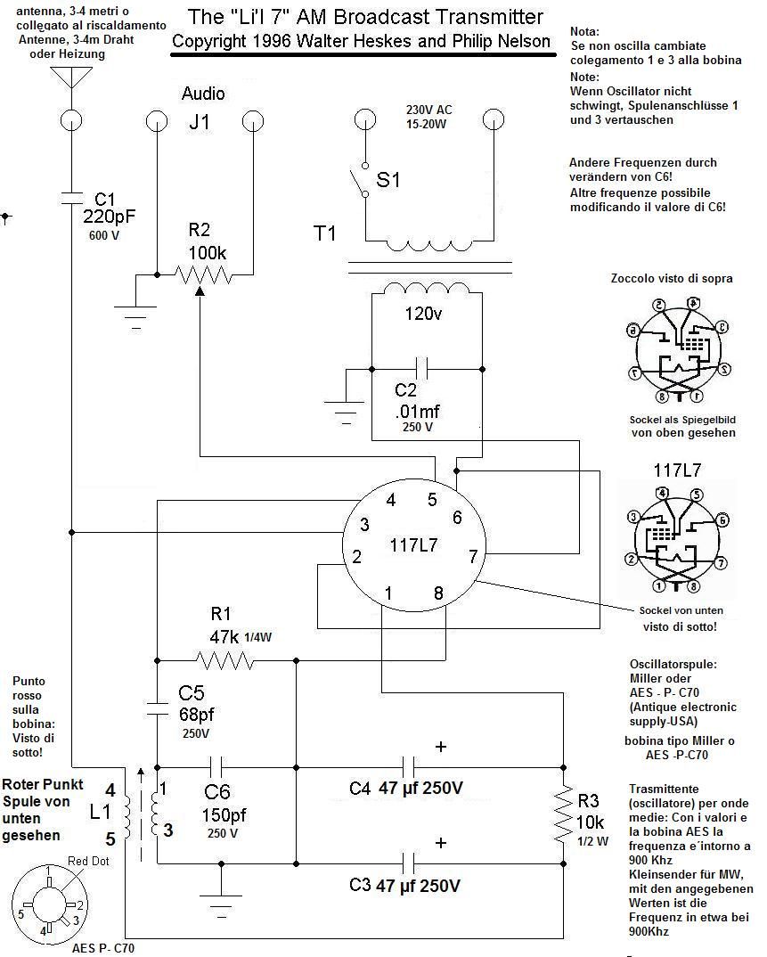
Schematic Diagram
This schematic will print on a single 8.5 x 11 sheet of paper if you
print it without any margins or header/footer information. We suggest
that you save the picture file and print it from a paint program
rather than printing this web page from your browser. To save the
picture in Internet Explorer, right-click anywhere on the
schematic, then choose Save Picture As.
If you are unfamiliar with schematics, the ARRL has a good beginner's article on how to read them
(Part 1,
Part 2).
Building Instructions
The first step in building the Li'l 7 AM transmitter is to
acquire all the needed parts. If you're an experienced
builder, you may find many of these parts in your
junkbox. For best results, we recommend that you stick with the
values given in the parts list.
If you haven't already done so, print these instructions and the
schematic. Read all of the instructions
before you start to build anything.
Enclosure
You can build the Li'l 7 on a breadboard or in any plastic
or metal box roughly 6 x 6 x 3 inches in size. Both AES and Radio Shack
supply suitable enclosures. Walter built
his unit in a custom-fabricated metal box, while I salvaged
an old plastic box that just happened to be the right size. If you
don't have metal-working tools, plastic is easier to work, of course.
If you choose a metal enclosure, you may want to add a
perforated board to your shopping list, to provide a safe
mounting surface for your components. If your enclosure is
plastic, you may be able to mount your smaller components
point-to-point between the major components and skip the perf board.
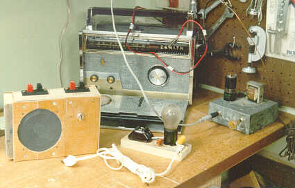
Here is a picture of Walter's workbench, showing the original
Li'l 7 in action. It's visible at the lower right, housed in
a custom-built metal enclosure. Visible on the top of Li'l 7 are the
117L7/M7 tube and transformer T1. Walter's Zenith TransOceanic Model 1000
serves as the test receiver. Also shown in the picture, although
not in use at this time, are a homemade test speaker used for radio repairs
and a Dim-bulb Tester.
Connector options
The parts list suggests a 4-jack gang phono connector to provide
handy connection points for your antenna and any input
connector(s) that you plan to use. Phil uses a portable CD/cassette
player's earphone jack for input, using a stereo mini-to-mini cord
from the player to the Li'l 7, and then a Radio Shack stereo/mini-to-mono/phono
adapter to complete the connection. Only two of the four available jacks
are used (one for audio input and the other for output). Depending on what you
want to use as input, you may want to replace the gang radio/phono jack
assembly with screw binding posts or other types of connectors. Or, if you
want to use your transmitter with more than one input device, you can
wire input jacks in parallel with each other using the suggested gang jack.
If you plan to experiment with different antennas, you may also want
to use a binding post or similar connector at the antenna end, rather
than soldering the antenna wire permanently.
Layout
Parts layout makes a big difference in ease of construction. Layout is not
too critical in this circuit. Just try to keep related parts
close together without making the assembly so tight that it's difficult to work
in your enclosure. Notice that a number of components connect to the chassis ground;
this may help you come up with a reasonable layout.
Walter and I both built our units with the tube sticking out the top,
which makes it easy to mount the tube socket, but also exposes the tube to
possible damage. You could also mount the tube inside your box, mounting
the tube socket sideways using an angle bracket. If you enclose the tube,
be sure to provide some ventilation holes.
Keep in mind that you'll need to adjust the RF coil L1 once the transmitter is assembled.
One way to mount the coil is to drill a small hole in the back or top of
your enclosure and glue the coil's small tube through the hole, allowing
access for adjustment. You can also glue the large part of the coil
directly onto your enclosure. Glue may not be necessary if the coil is supplied with a mounting
lug or clip that fits into the chassis through-hole and locks the
coil assembly to the chassis. Use glue sparingly and do not cover
the coil with glue; the glue can affect the inductance of the coil.
Enclosure
Once you have a sensible layout, make a sketch and set all the parts
aside while you create the needed openings or attachment points in your box
or breadboard.
After creating the attachment holes and points, do a test assembly of
all the attached components to make sure everything will fit as planned.
This is the time to make any last-minute
revisions before you fire up the soldering gun. You should also
plan the order in which you'll attach the parts.
Assembly
Now it's time to start hooking everything up. Work slowly
and check off every part against the schematic and parts list as you go.
Remember the old joke about, "I haven't got time to do it right, but
I do have time to do it over!"
Begin by mounting the major components—the tube socket, transformer,
potentiometer and switch, pilot light, and the jacks. Once these big parts
are in place, connect the smaller ones.
It's important to hook up the coil correctly—if you don't, the
transmitter may not work at all. The numbers 1-2-3-4 shown in the
schematic match the numbers of the pins on the RF coil as
shown on the data sheet included with the AES part. The red dot on
the coil helps you identify the pins; it is located between pins
1 and 2. A diagram of the pins and the red dot appears in the lower
left corner of the schematic. Important: the pin numbers on
the schematic are given as if you are holding the coil assembly with the larger of the two coils closer to you.
In your initial assembly, leave the coil connections
unsoldered until you have tested the unit and confirmed that the
coil is working correctly. That will make it easier to change
things around if you got something backwards.
In the schematic, note that three points are labeled with the ground symbol.
These should all be connected together (this schematic-drawing convention is
explained in the schematic tutorial referenced earlier). Do not connect them
to anything else.
When everything is hooked up, take five minutes to recheck every
connection against the schematic, paying special attention to the values
on similar-looking components.
Antenna configuration
The best antenna for this transmitter is a vertical antenna
four feet in height. Just about any kind of wire will do, although
a cheap whip (telescoping) antenna attached vertically to the
enclosure will give a neater appearance. There
are many local factors that will affect a small transmitter, such as the
wiring and plumbing inside your home, nearby radiation sources, and so on.
Feel free to experiment with your antenna configuration. A longer antenna
may not necessarily give better performance, however.
Tuning the transmitter
The moment of truth has almost arrived. Now it's time to tune the transmitter
to broadcast on a quiet spot on your local AM dial.
Before you plug in the transmitter, turn on a nearby AM radio and try to find
the quietest possible spot on the dial between about 800 and 1000. Make sure
that everything else is in place and connected—your input source, the
antenna, and the adjustment tool to adjust the coil L1.
Here's how to tune the transmitter:
- Remove antenna wire from transmitter.
- Turn on Lil'7.
- Connect modulation source (casette player, phono, etc.) to the Li'l 7 transmitter's input jack.
- Turn on your modulation source.
- Turn on a nearby AM receiver and turn the volume up about halfway.
- Wait two minutes while all three units warm up.
- Tune the receiver to a clear spot between 800 and 1000 on the AM broadcast band.
- Using your coil adjustment tool, slowly turn the core of of the coil until you hear the modulation source playing through your receiver.
- Adjust the tuning dial of your AM receiver so that you have the smallest possible amount of heterodyning (whistling or interference) with adjacent stations on the dial.
- Readjust the coil core as needed to obtain the maximum sound volume at your AM receiver.
- Reconnect your antenna wire to the Li'l 7 AM transmitter.
Did it work?
At this point, you should have a working AM transmitter. If you don't hear any sound at all, power everything down, take your Li'l 7 back to the workbench, and check all the wiring against the schematic in case you miswired something. Remember, a miswired coil may prevent the transmitter from working. If the signal is audible but weak, check the input levels on your modulation source and repeat the tuning procedure from the very start. If you're using an earphone jack as your source, you may need to turn up the volume pretty high.
If your transmitter works properly, finish soldering the coil connections. You're done!
Again, antenna characteristics can greatly affect the performance
of low-power transmitters. You may get very different results using
different lengths and configurations. Your antenna's characteristics
also affect how directional it is (i.e., how strongly it broadcasts
in a particular direction). There's no single antenna that's be perfect
for every location, so be prepared to experiment a bit before you
find the best solution for your particular setup. Antenna design
can be quite complex. If you get interested in the topic, check out
your local library—there are a number of books on the subject.
Refinements
Since we first published this design, fellow collector Ron Olexa wrote
in to suggest adding a fuse as an extra safety factor.
A fuse will minimize damage in the event of an accidental short
circuit while you're testing or using your Li'l 7. We recommend connecting
a 2-amp slow-blow fuse between the on/off switch and
the 120v AC line cord.
If you come up with other improvements or suggestions, please
send them along
so that we can share them with other experimenters.
How the Li'l 7 Works
The heart of the Li'l 7 transmitter is the 117L7/M7 GT tube. (Note that 117L7
and 117M7 tubes are interchangable. Some references may list one or the other,
or use the number 117L7/M7.) In a single envelope, this tube combines both a
diode and a pentode. Its filament runs on 117 volts, which simplifies the
power supply. Here are the tube internals.
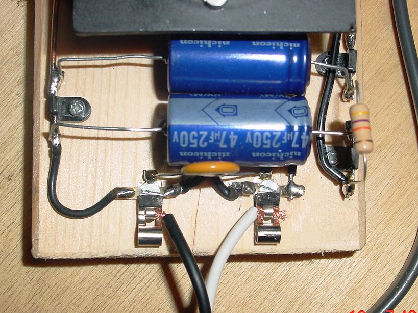
The diode portion of the tube rectifies the incoming AC line voltage,
changing it to a series of DC pulses. The electrolytic capacitors C3 and
C4 soften these pulses and provide smooth B+ voltage.
Isolation transformer T1 is strongly recommended. Although the transmitter
will work without it, it prevents a possible shock hazard when the chassis
or any other normally grounded point is touched. Any small transformer delivering
up to 150 volts at a few milliamperes will work. The transformer also supplies
12 volts AC, which we used to power a pilot light.
The pentode portion of the tube combines both the oscillator and modulator.
The novelty of this circuit is that the pentode screen is returned to ground
rather than to B+ as might be expected. The modulation input varies the
pentode screen voltage about 1 volt above and below ground potential.
The circuit across the cathode (pin 8) and the suppressor grid (pin 4)
oscillates at the frequency determined by the LC circuit composed of capacitor
C6 connected across the primary of the tunable coil. This becomes the carrier wave.
The carrier wave is modulated (or shaped) by the electrons injected onto the pentode
screen by the modulation source. Electrons are both oscillated at the carrier
frequency and modulated at the signal frequency before they hit the plate and
step off the antenna. The receiver then detects these electrons and strips away
the carrier wave from the modulation signal, which is amplified and transformed
back into audible sound.
You can shift the Li'l 7's broadcast frequency either by moving the iron core of the coil or
by changing the value of capacitor C6. With C6 at 150pf, the oscillator tunes to a vacant
spot around the midpoint (800 - 1000 KHz) of the AM broadcast band.
A smaller value for capacitor C6 increases the oscillator's frequency; a larger value decreases
the frequency. You can experiment by placing a 68 pF capacitor
in series with the 150 pf capacitor to drop the total capacitance to about 50 pF.
At that value, you may be able to tune Li'l 7 to the upper end of the
broadcast band, possibly around 1700 KHz or higher. To tune the lower end of
the band, try placing a 68 pf capacitor in parallel with the 150 pf one to raise C6
to about 220 pf. The idea is to customize your transmitter for the frequency
that works best in your setting.
If you're really adventurous, install a rotary switch in series with different
stepped values of C6 (for instance, 50 pf, 150 pf, 200 pf, 300pf), to allow
tuning across a wide range of broadcast frequencies. That selectability feature
would make the transmitter universal for regions where it is nearly impossible
to find a vacant channel in the middle of the broadcast band. It's also fun to
refine a working design.
Possible modulation sources include the speaker voice coil of a radio,
a crystal microphone or piezoelectric phono cartridge, the tape output terminals
of an AM/FM receiver, or the earphone jack of a radio, tape machine, or CD player.
Li'l 7, European Style
In 2014, fellow collector
Volker from Italy sent me photos of his
Li'l 7, along with a schematic translated into German and Italian.
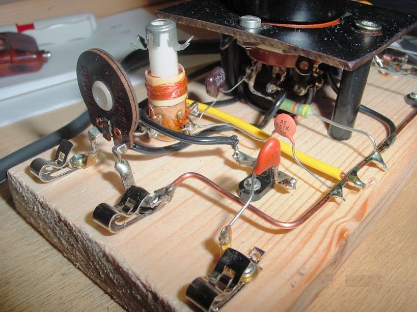
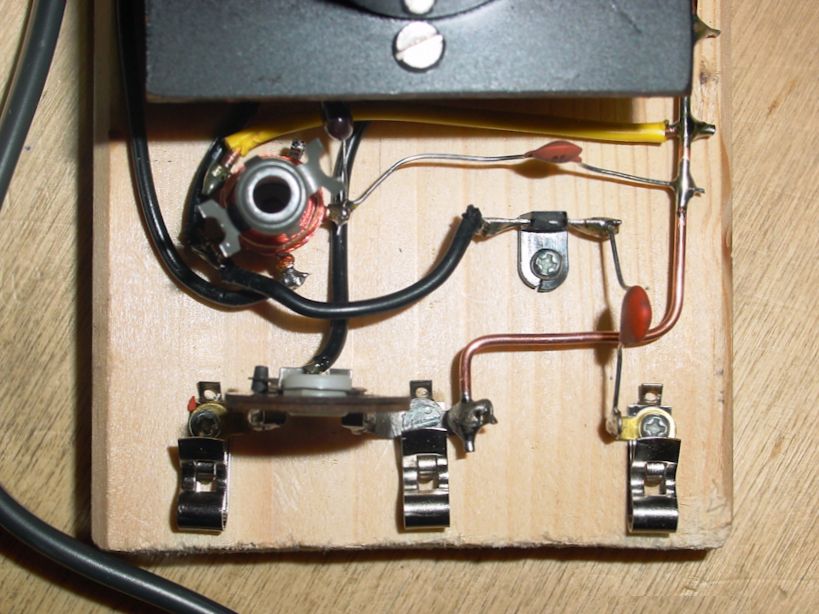
He used techniques that were employed in the earliest days of
radio, basing the transmitter on a wood platform and dispensing with a cabinet.
He also used Fahnestock clips and right-angled buss wiring remeniscent of days gone by.


Like old-fashioned breadboard projects, Volker's version has exposed wiring that presents a shock danger.
Obviously, this style is not recommended for children! Do not employ this technique if your household
includes anyone who does not have the common sense to avoid touching bare wires.
If you have built a Li'l 7 transmitter and wish to share your photos, kindly send me an email.
This radio construction project, including all descriptions, diagrams, photos, and the underlying electronic design, is published here for the noncommercial use of radio hobbyists. You may print and reproduce these project instructions for your personal use. Commercial use of this material is strictly forbidden.
|