Hallicrafters SX-88 Review
QST Magazine, June 1954
(Thanks to Peter Bertini for providing a copy of this QST article.)
Sooner or later some wit is going to come up with the facetious remark that, "That new SX-88 is sure a lot of receiver—it's 20 inches wide and 18 1/4 inches deep." And while it's true that 18 1/4 inches is deep for a receiver and may occasionally pose a problem in finding operating-table space, there's quite a bit more to the story.
This Hallicrafters receiver has already been advertised extensively, so some of the data you find here may be old hat. Bear with us, however—some of it hasn't been in the ads.
The SX-88 is a double-conversion two-dial receiver that covers 0.535 to 33 Mc. in six ranges. The bandswitch also operates masks in back of the dials so that only portions of the scales, corresponding to the range in use, are back-illuminated at any time. To facilitate setting up on any amateur band, a 100-kc. crystal-oscillator "Calibrator" is included—when changing to a new ham band you throw the bandswitch, turn the "Calibrator" on, set the bandspread scale to some even 100 kc. within the ham band and set the bandset dial to a dot at the high-frequency end of the band. At this point you will be within easy reach of the 100-kc. marker signal so you rock the bandset dial, zero on the marker signal, and lock the bandset dial. The bandspread dial then reads directly in frequency, and you can, of course, check it every 100 kc. with the calibrator signal. The calibration marks on the bandspread dial are every 10 kc. on the bands up to and including 14 Mc. (they're every 20 kc. at 21 Mc. and every 50 at 28 Mc.), so it can be read easily to about 3 kc. (except on 21 and 28 Mc.) and closer if one is a good judge of distance.
|
|
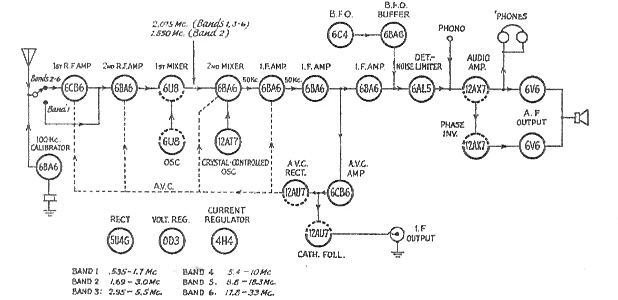
Figure 1. Block diagram of the SX-88 receiver. Only one r.f. stage is used in the broadcast range—all other ranges use the two r.f. stages. The first i.f. is normally 2.075 Mc. Band 2 includes this frequency, however, so on Band 2 the first i.f. is made 1.550 Mc. The 4H4 current regulator is in the heater circuit of the 6U8 1st mixer, for maximum stability under varying line-voltage conditions.
|
The receiver has a lot of selectivity (as we'll elaborate on later), and there might be times during c.w. operation with high selectivity when a 3-kc. approximation of frequency wouldn't be good enough to allow one to return from some other part of the band to a signal he had been stalking previously. (As, for example, in a DX contest when you're trotting back and forth between several pile-ups.) For such cases, there are arbitrary markings on both the scale and the tuning knob that give a 0-2400 scale for logging and reset.
This receiver has no "selectivity" control and no crystal filter—it has a "Bandwidth" switch. This switch has six positions (not counting a seventh marked "Phono" for feeding a record player through the audio amplifier), and those positions are marked ".250," ".500," "1.25," "2.50," "5" and "10." These figures represent in kilocycles the 6-db.-down bandwidths of the 50-kc. second i.f. (the first i.f. is 2075 kc., except on one range), and the corresponding 60-db.-down bandwidths are .850, 1.50, 3.75, 7.5, 15 and 21 kc. If you dig back through old copies of QST, you will find that this degree of selectivity exceeds almost anything that has been described by home constructors, with only a few exceptions in the case of "super-selective" c.w. receivers. It certainly is better than anything that has been described in the way of graduated selectivity, because it goes all the way from a nominal 250-cycle bandwidth to one of 10 kc.
The two sharpest positions give the kind of selectivity that the "super-selective" c.w. gang has been plugging for the past few years: no audio image at all on "the other side" of zero beat. On 'phone, the 5-kc. setting is used when there is no QRM, the 2.5-kc. bandwidth is right for s.s.b. reception of a.m. or s.s.b. signals, and the 1.25-kc. bandwidth is useful for tough QRM on a.m. or s.s.b. The b.f.o. should be used for exalted-carrier reception of a.m. signals at the 1.25-kc. bandwidth, although two operators reported that it isn't absolutely necessary—we rate them as "old pros" at copying 'phone and not necessarily typical.
The SX-88 has a five-position switch labeled "Response" and marked with such old irritants as "Bass Boost," "Hi Fid " and " Normal," and a couple of new ones marked "Comm 1" and "Comm 2." (Right about now you're wondering if the author has gone off his rocker, running some guff about a glorified tone control in the middle of a description of the selectivity characteristics.) The "Bass Boost" and "Hi Fid" positions are ones to be used with b.c. reception or phonograph-record playing, of course, and the "Normal" is the usual audio response of a communications receiver, dropping off at the higher audio frequencies to attenuate the background noises a little. The two sleepers, "Comm 1" and "Comm 2," are useful for 'phone reception, and should do a lot to overcome some of the criticisms one hears about the audio "quality" when using selectivity. These two positions provide attenuation at both the high and low ends of the audio range, to give a better over-all balance to speech received through a selective i.f. amplifier. (An S-76 was reworked along these lines in the lab about six months ago, and it made a whale of an improvement. All it required in that case was smaller audio coupling condensers and a couple shunting the grid resistors—it took the " boominess" out of speech in the higher-selectivity positions.)
Regulated heater current to the h.f. oscillator seems to be the trend. The SX-88 uses a 4CH4 for the purpose—it should help where a high-powered transmitter drags down the line voltage during "transmit" periods.
The next remark may sound facetious, but it isn't meant to be. One of the most important design features of a receiver is the tuning knob(s) and mechanism. It is also one of the most controversial subjects when receivers are discussed. So about all we can do is to report that the tuning knob(s) of the SX-88 is weighted (to give some inertia to work against) and free-running enough to be easily spun several revolutions. The drive is spring-loaded gears. It takes 17 1/4 revolutions of the bandspread knob to cover the 500 kc. of the 80-meter band, 14 revolutions to cover the 300 kc. of 40 meters, 17 revolutions for the 350 kc. at 20, 7 2/3 revolutions for 450 kc. at 15, and 11 revolutions for 1700 kc. at 10 meters.
The S-meter is a dual-scale affair. One scale is the usual S1 to S9 and on up to + 40 db., and the other is shown in microvolts input to the receiver. The instruction book points out that the microvolt scale holds closest on bands 2 and 3, a bit of information that may come as a shock to those who place the reliability of an S-meter's calibration just one notch above that of the standard-frequency transmissions from WWV. The S meter works from the plate current of the first r.f. stage, an a.v.c.-controlled stage, and, since the a.v.c. is unaffected by the b.f.o. and can be used with c.w. as well as with 'phone, the S-meter indicates on c.w. signals. However, the no-signal setting of the S-meter depends upon the setting of the "Sensitivity" (r.f. gain) control, so if the r.f. gain is backed off the S-meter is less responsive. With an a.v.c. and S-meter system like this, it means that a.v.c. can be used in the reception of s.s.b. signals, a feature that may prove useful in some of the s.s.b. round tables where the signals are at considerably different levels.
The receiver has other features that may prove useful to specializing operators. For example there is a convenient cathode-follower take-off at the tail end of the 50-kc. i.f., for external connection to a teletype converter or an oscilloscope. This is an auxiliary gain control (inside the receiver cabinet) that cuts into the circuit when the "Rec-Standby" switch is thrown to "Standby." This enables the operator to switch on his transmitter and simultaneously reduce the gain of the receiver to a condition suitable for monitoring his own signal. This operation can also be performed by a remote switch, or the "Rec-Standby" switch can be used to control one's transmitter. A small neon bulb from grid to ground on the first r.f stage is included to protect the receiver from high-level r.f. signals, but the operator is cautioned that r.f. on the antenna terminals in excess of 50 volts may destroy the neon bulb and antenna stage coils.
The I.F. Amplifier
As an "old skirt-selectivity man," the writer was particularly interested in the 50-kc. i.f. amplifier, and we'll take a little time here to tell you how the SX-88 gets its wide range of bandwidths. The heart of it is, of course, the tuned circuits that are used. These are special coils tuned by a ferrite slug and surrounded by a ferrite sleeve. The special design gives a coil with a Q of 175 to 185 at 50 kc., as compared with the Q of 100 of the coils used in the S-76. An interesting sidelight is that it was found impossible to obtain a Q of higher than 130 until a metal screw was removed from the ferrite core and a means was found for threading the glass-hard and glass-brittle ferrite.
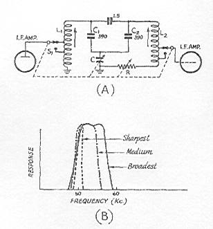
Any skirt-selectivity man can build a sharp i.f. amplifier if someone hands him a bunch of Q = 180 coils, but the SX-88 i.f. has the various bandwidths mentioned earlier. This poses quite a problem, because the frequency must not be changed radically by the bandwidth-variation method, and the gain must be held substantially constant. This was accomplished by the Hallicrafters engineer in the general way shown in Fig. 2A.
|
|
Figure 2. (A) Basic circuit of the variable-bandwidth i.f. used in the SX-88. The coupling is increased as C is made smaller, and the Q of L2C2 is reduced as R is increased. The stage gain is held constant with changes in bandwidth by tapping the grid and plate up or down on the coils. (B) The effect of varying C and R in (A) is that the passband "grows" out to a higher frequency, as illustrated here.
|
This simplified diagram shows a variable condenser ganged with a variable resistor—in the actual receiver these are step-switched, of course. It can be seen that the smaller the capacity of C, the tighter will be the coupling between the two tuned circuits, L1C1, and L2C2. Furthermore, the larger the value of R is made, the lower becomes the Q of the grid tuned circuit, L2C2. By proper proportioning of the various values of C and B (at different switch positions), the wide range, in bandwidth variation is obtained. One of the three 50-kc. i.f. stages has taps on the coils, as represented in Fig. 2A by the leads to S1, and this enables the gain of the i.f. amplifier to be held relatively constant over the entire range.
The midband frequency of this i.f. system does not remain constant—the low-frequency edge remains substantially constant. This is illustrated in Fig. 2B, and it is something the operator must remember if he is to understand fully the performance of the receiver as the bandwidth is changed. Here three conditions ("sharpest," "medium" and "broadest") are shown—the effect is as though the bandwidth "grows" to the higher frequency. It is pointed out here to explain what will undoubtedly puzzle some operators when they switch bandwidths and find that sometimes the carrier drops out and sometimes it doesn't. Obviously, it will depend on whether one has the carrier centered at around 50 kc. or on the high-frequency side of the i.f passband.
The B. F. 0.
The SX-88 has a three-position switch marked "C.W.," A.M.," and "S.S.B." This is no magic switch that makes the tuning of s.s.b. signals an a.m. man's delight, but it is worth explaining, It is the usual b.f.o. "on-off" switch with something added. In the first place, the b.f.o. has a "b.f.o. buffer" stage between it and the diode detector. On "A.M." the b.f.o. is turned off, and on "C.W." extra resistance is cut into the cathode of the b.f.o. buffer, so that the b.f.o. voltage reaching the detector is less than when the switch is flipped to "S.S.B." With manual gain control, there seems to be insufficient b.f.o. injection for s.s.b. signals when the b.f.o. switch is on "C.W.," provided the manual gain is reduced sufficiently. However, the extra b.f.o. voltage on "S.S.B." is necessary when running with the a.v.c. on and the manual gain turned up, and that may be the reason for the two positions. Or it may be there to minimize the phase distortion at the detector that can result from insufficient b.f.o. injection in any event, we found that we needed it when receiving s.s.b. signals with the a.v.c. on and the manual gain turned up. Of course; just having a switch marked "S.S.B." doesn't solve all of the problems of receiving a s.s.b. signal—you still have to tune one in more carefully than you do an a.m. signal, and we wouldn't want you to assume otherwise. But with the wide range of available selectivity, the boosted b.f.o. injection, and the slow tuning rate, the SX-88 engineers did not overlook the features considered necessary for good s.s.b. reception.
—B. G.
|