H.H. Scott Model 210-B Amplifier (1951)


 Schematic
This beautiful little monophonic amplifier harks from the early
days of the 1950s "hi-fi" movement which revolutionized home
listening for millions of people across the world. Built in 1951, it's
the same age as I am. It also introduced
me to the world of vintage audio gear, broadening my horizons as
a collector.
I found this gem at a local shop, jumbled in with many boxes
of old parts, books, and miscellany that had just come from a retired
radioman's estate. That might sound like a radio collector's dream
come true, but after much digging, I found only
two interesting items. One of them is a very peculiar 1920s
RCA radio chassis, which I'll get around to photographing
one day Real Soon Now. The other was this copper-colored unit.
Covered with dust and grime, it didn't look particularly appealing at first. But
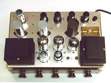
then I read the metal plate on the chassis identifying it
as a "Dynaural Laboratory Amplifier" made by the Herman
Hosner Scott company in Cambridge, Massachussetts. I had no idea what
Dynaural meant, but I recognized H.H. Scott as an audio
manufacturer, and the amp appeared to be well built, with ten
tubes and hefty transformers.
Lugging
this amp and the RCA radio chassis to the front of the store, I asked
what the price might be. "Eight for the radio and seven for
that other thing," the proprietor replied. Figuring that ten tubes alone were
worth at least seven dollars, I cheerfully handed over $15
and departed.
Description
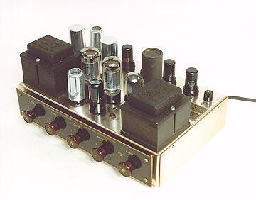
With its open-chassis "bowling alley" design, this old Scott might
look primitive to modern eyes, but exposed tubes and transformers
were common in high-end audio and radio gear.
The lustrous copper-colored chassis is made of
anodized aluminum, a metal which does not tarnish. Only
a light cleanup was required to bring it back to like-new condition.
Molded in the bells of the two black transformers is the
distinctive H.H. Scott logo. Each knob on the front also
sports the logo, in gold against brown plastic. Behind the
knobs is a faceplate of brown wood-grained plastic. The
faceplate is offset about
half an inch from the chassis front, probably to facilitate mounting
in a custom cabinet. As far as I know, factory cabinets were not
available for this amplifier.
Rated at 20 watts of output, the amplifier uses two 6L6GT audio
output tubes in a push-pull configuration. As found, mine had
two unmatched output tubes—one glass tube that tested weak, and
a metal one that tested within normal range. In the photos above,
taken after restoration, the output tubes have been replaced with a new
matched pair of 6L6GTs. They are the pair of large glass tubes
near the middle of the unit.
As found, the amplifier sported the original cardboard display card which
fits above the faceplate and gives information about the amp's features
as well as brief "getting-started" user instructions. The card
has the look of a dealer's showroom item, but who knows,
perhaps it came along with every amplifier. I kept mine,
anyway, for authenticity's sake.
Operation
This amplifier has two inputs, labeled Amp and Pre-Amp. The Amp
input is suitable for connecting a radio tuner. (In 1951,
radio meant AM or monophonic FM. True FM stereo
broadcasts were still several years in the future.)
The Pre-Amp input provides additional amplification, for use with
a phonograph. The output connectors let you use a speaker of any impedance
between 1 and 24 ohms; I use an 8-ohm speaker.
There are five main controls on the front of the unit. The leftmost four
are labeled Bass, Treble, Volume, and
Dynaural (noise filter). The rightmost control combines the power switch
with three Range settings marked at 6, 12, and 22 kilohertz.
On the back of the amp is a small
variable potentiometer called the suppressor level control.
The following portion of the owner's manual describes the amp's operation.
The Range control provides a sharp high-frequency
cutoff for reduction of distortion and noise above the cutoff frequency
in kilocycles. For normal record playing, this control should be turned
to 12; the range on old, worn or distorted records should be reduced
to 6, and on high-quality vinylite records and FM programs the 22kc
range can be used.
The Suppressor is completely inoperative when the Dynaural control is
turned to Off. The control should be advanced only as far as necessary
to reduce the noise to a satisfactory level. The mid-position is usually
adequate except for very noisy records.
The Treble and Bass controls provide a boost when turned to the right
from mid-position, and attenuation when turned to the left from mid-position.
The setting of these controls depends on the type of record played,
the speaker, the acoustics of the room, and the listener's preference.
The Suppressor Level control on the rear of the amplifier chassis
compensates for the various output voltages of different pickups.
If the control is set too high, noise will be heard superimposed
on the loud passages of the music. When it is set too low, the music
will be dull and muffled. The best setting is that at which all
records can be played by merely readjusting the panel controls.
Some of this fancy noise suppression technology is wasted
if you use this amp with a CD player, but it still
offers good flexibility and that rich "tube-y" sound.
Electronics and Restoration
With ten tubes, this little amplifier has twice the number of
a typical "All American Five" tube radio. Here's a list of the
firebottles and their functions.
| Tube |
Function |
| 12SL7 |
Pre-amplifier |
| 6J5 |
1st AF amplifier |
| 6SG7 |
Treble gate |
| 6SG7 |
Bass gate |
| 6SQ7 |
AF control |
| 12SL7 |
2nd AF amplifier |
| 6SN7GT |
3rd AF
Amplifier/Phase Inverter |
| 6L6GT |
Power output |
| 6L6GT |
Power output |
| 5V4G |
Rectifier |
As found, this amplifier was in original condition. No repairs
had been made, other than replacing the output tubes. I cleaned
and inspected it inside and out, then slowly powered it up on my
variac over a period of a few hours, to give its electrolytic
capacitors a chance to re-form.
The amplifier worked, after a fashion. The volume and
tone were reasonable, but after several minutes of operation
it emitted distinct crackling and hissing sounds.
This kind of distortion can come from a variety of sources,
from a bad resistor to something as simple as dirty tube
contacts. Before going any further, I removed each tube
and tested it, then very meticulously cleaned each pin,
as well as every socket. I also gave the innards a close
inspection for burned-looking resistors.
Apart from the weak 6L6 tube mentioned above, all of the tubes
tested at reasonable levels. To eliminate tubes as a source
of the snap-crackle-pop, I substituted known-good tubes in each socket, one
by one. This still didn't eliminate the problem, so I concluded that
tubes were not the source. (Note that an emission-type tester, such
as the one I use, won't necessarily identify a noisy tube. It merely
tells you if the tube has short circuits and whether it emits within
a specified range.)
I also cleaned all of the controls, using DeOxit spray cleaner.
A couple of them required partial disassembly before I could
get cleaner inside the control.
The next step, which took several hours, was to replace all of the old
paper and plastic capacitors. In the course of this work, I also
took a very close look at the wiring, looking for loose connections,
solder bridges, and so on.
I was quite impressed with the quality of this amplifier.
Good-quality components were used, the layout was orderly,
and the factory wiring was very neat. I tried to make all of
my replacements look just as clean.
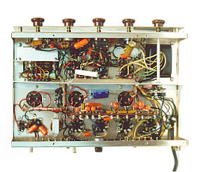
Departing from my usual practice in restoring radios, I decided not
to replace the original power-supply filter capacitors. After I
re-formed those caps on the variac, the amplifier showed no trace of hum.
As you can see in the top view, these capacitors
are very prominent. They are the three large tubular
components—two shiny aluminim and one black cardboard-cased—mounted
in a horizontal row across the middle of the chassis. Although I could get
replacements that are electronically equivalent, they would not look the same.
As long as these guys continue to work fine, I'd rather preserve the amp's
authenticity.
At the end of the long capacitor-replacement process, I was disappointed
to find no improvement in the snap-crackle-pop problem. Feeling stumped,
I queried the rec.audio.tubes USENET newsgroup, hoping to get
some good advice.
In addition to cleaning the tube connections, which I had already done,
a couple of folks suggested bad solder joints as a cause. Although the
factory soldering looked very good, I carefully resoldered every connection
in the signal path—another long, painstaking procedure. I also replaced
a few resistors in critical spots, following suggestions by another
newsgroup member.
The result was . . . no improvement! That's where I left this project
for about a year. The amplifier sounded very good for the first
few minutes, until the crackling and hissing began. One idea would be
to break out the freeze spray, in hopes of identifying a component (resistor?)
that starts to generate the noise after it heats up. This technique helped
me diagnose a heat-related problem in my old RCA TV.
1999 update: Well, for the first—and probably the last—time in
my experience, one of my projects actually healed itself. This amplifier sat in a box for
over a year while I was occupied with other projects. Then one day, having seen
an interesting 1950s tuner, I remembered the amp and decided to take another whack
at the Rice Krispies problem.
Unlimbering my signal generator and other gear, I set up the amp on my
workbench, along with a CD player as input, and let it warm up for a while.
When a few minutes passed without producing the familiar crackle, I left the
workshop for about half an hour, then came back.
Still no crackle. What's going on here? Okay—perhaps with the bottom cover
removed and standing on its side, the amp's not generating enough heat to trigger
the problem. Pop the cover back on, stand the amp upright, let it play for another
half hour.
Still no crackle! Could it really be fixed? Apparently so. After installing the amp and
CD player on a shelf next to my workbench, I have played it regularly
for several months. It performs magnificently, with no trace of
hiss, crackle, or other distortion.
2006 update: Several years after first posting this article, I got some email from a restorer who suggested that
the crackle might have been a result of the old electrolytic capacitors slowly reforming.
I got this amp very early in my career as a collector. If I found it today, the first thing
I'd do would be to replace the electrolytics, since they are so often faulty. These electrolytics still
seem to be holding up, but you never know.
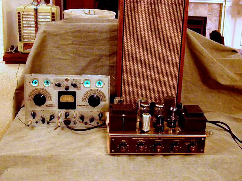
Just for fun, I have occasionally used this gem as the amp
for my RCA Rider Chanalyst operating
as a radio receiver.

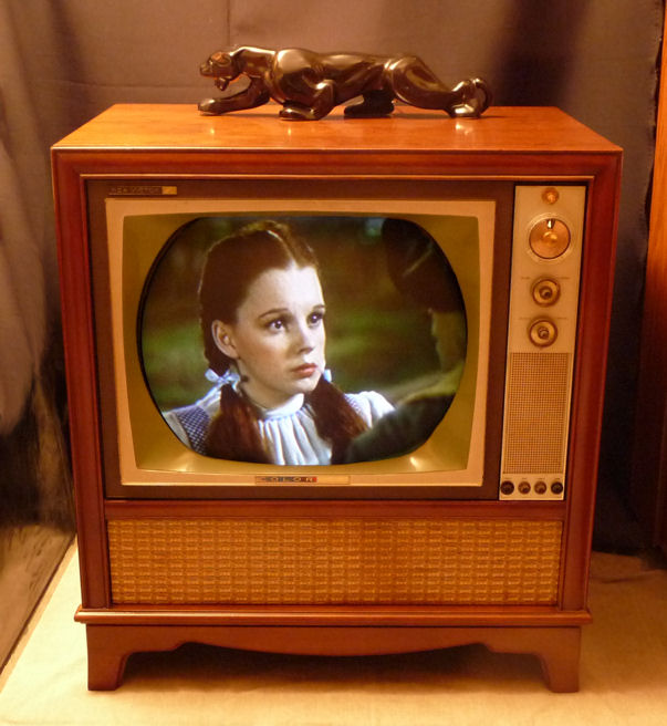
After owning the amp for quite a while, I traded it to another collector for an
RCA CTC-11 color television, which looked like
this after restoration.

|