RCA Model 21T227 Console Television (1952)


When I saw this large console TV at a local shop, I decided that it needed a new home. Restoring it was a big project, but the results were gratifying.
Description
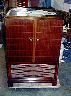
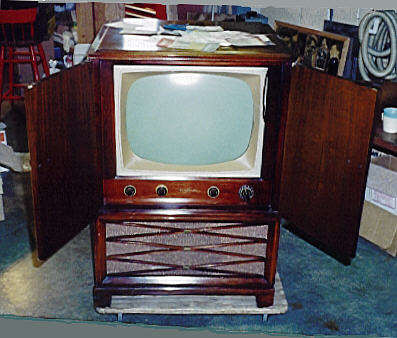
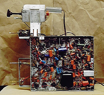
The first photos show the set in my messy garage the day I brought it home.
This television was made in 1952, when I was about one year old. Like other TVs of the time, it tunes only VHF channels 2-13.
Needless to say, it is a black and white receiver.
With a 17-inch screen and a 10-inch speaker, this television looks and sounds great. A two-position tone control lets you select normal or extra bass. It also has a Phono switch in the front and a phono jack in the back, allowing you to plug in a record player.
The mahogany veneer cabinet has large front doors that swing open to expose the screen and controls. When I bought this TV, the cabinet was in average shape, with a few scratches here and there but no serious damage.
The electronics needed work. When you turned on the set, its screen showed only a bright horizontal line in the middle. Not too encouraging, but at least the picture tube showed signs of potential life. The audio sounded fine, suggesting that the tuner and audio circuits were operational. The TV had obviously been serviced in the past. Its cabinet interior was littered with an interesting collection of old service literature and discarded parts.
Cabinet Restoration
Restoring the cabinet finish took about two hours, spread over two days. I began by wiping the entire cabinet with paint thinner to remove dirt and any old polish. Then I lightly buffed it with very fine (#0000) steel wool and wiped it with a tack rag.
To conceal the scratches, I wiped on a thin coat of red mahogany Min-Wax stain. This cabinet has large surfaces, so I worked quickly, one surface at a time, wiping over and over to ensure a smooth and very thin coat. Cotton Q-tip swabs made it easy to reach small corners and crannies in the speaker grille.
Letting the cabinet dry overnight, I then sprayed on two coats of clear lacquer to protect the new finish. Before spraying on the lacquer, I covered the speaker cloth with cutout pieces of newspaper stuck between the cloth and grille pieces.
Electronic Restoration
If you were looking for a "classic" 1950s television design, this would be a good candidate. It uses 23 tubes as follows.
|
Tube |
Type |
Function |
|
V1 |
6CB6 |
RF amplifier |
|
V2 |
6J6 |
Converter |
|
V3 |
6CB6 |
1st video IF amplifier |
|
V4 |
6CB6 |
2nd video IF amplifier |
|
V5 |
6CB6 |
3rd video IF amplifier |
|
V6 |
12AU7 |
Video det./Vert. sync. separator |
|
V7 |
6AC7 |
Video output |
|
V8 |
6AU6 |
AGC keying |
|
V9 |
6AU6 |
1st sound IF amplifier |
|
V10 |
6AU6 |
2nd sound IF amplifier |
|
V11 |
6AL5 |
Ratio detector |
|
V12 |
6AV6 |
AF amplifier/AGC clamper |
|
V13 |
6K6GT |
Audio output |
|
V14 |
6SN7GT |
Horiz. sync. sep./Sync. amplifier |
|
V15 |
6J5 |
Vertical oscillator |
|
V16 |
6K6GT |
Vertical output |
|
V17 |
6SN7GT |
Horizontal AFC/oscillator |
|
V18 |
6BQ6GT |
Horizontal output |
|
V19 |
6W4GT |
Damper |
|
V20 |
1B3GT |
High-voltage rectifier |
|
V21 |
5U4G |
Low-voltage rectifier |
|
V22 |
5Y3GT |
Low-voltage rectifier |
|
V23 |
17QP4 |
Picture |
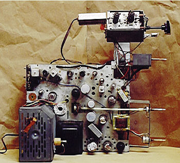
The next photo shows an overhead view of the chassis.
In this view, the TV's controls are located along the right. The tuner and fine tuner appear at upper right, projecting from the small "outrigger" subchassis that carries the tuner and RF tubes. The high-voltage cage appears at the lower left. It contains the high-voltage rectifier, damper, horizontal AFC/oscillator, and horizontal output tubes.
Restoring the electronics took a lot more time than touching up the cabinet. The first steps were standard: cleaning grime from the chassis and spraying contact cleaner (DeOxit) inside all the controls, paying special attention to the tuner mechanism.
Since I expected this project to be complex, I started a new notebook in which to record the results of every test and component replacement. This is a good practice in every restoration, although I have often skipped it in simple radio projects.
The first components to be tested were the 22 small tubes. Although a few seemed a bit weak, all tested within normal limits. The picture tube lit up, so I assumed that it was OK for the time being. I didn't have a picture tube tester, anyway! Absent further evidence, I would assume that tubes were not a primary trouble source. Phoning Antique Electronic Supply, I put in an order for a schematic and some replacement tubes.
(Nowadays you can order the service manual directly from Sams:
Set 184, Folder 12.)
Vertically Challenged
I was far from an expert TV repairman when I tackled this job (my previous two TV projects were a
1957 RCA and 1957 Zenith). It didn't take much expertise to diagnose the initial problem, however. A bright horizontal line indicates the loss of vertical deflection.
In normal operation, the TV sweeps the screen with 525 horizontal lines, sixty times a second. Its vertical circuits provide the proper deflection to cover the whole screen from top to bottom. If the deflection circuit fails, all the lines collapse into a single horizontal line at the center.
Caution: if a TV displays this telltale bright horizontal line, avoid playing it for any length of time (or at least
turn the brightness all the way down), or you may burn a permanent dark line in the phosphor of the picture tube.
Although the schematic had not arrived yet, the label inside the cabinet identified the tubes and their functions. Accordingly, I started testing and replacing capacitors associated with the vertical tubes. To keep track of what I was doing in the notebook, I sketched a simple layout of the tubes and assigned them arbitrary numbers.
Once I started replacing capacitors, it was hard to stop! This set employs over 100 capacitors, many of them the dreaded paper units. In the course of a couple of evenings, I filled three pages in my project notebook with paper cap replacement notes.
When I tried out the TV, the vertical deflection problem had been cured. The picture filled the whole screen from top to bottom!
We still had serious problems that couldn't be cured by adjusting the external controls. The picture was too dark and much too narrow. Black "empty space" appeared on each side of the screen. And, although stable, the picture was vertically offset. The bottom half appeared on top of the screen, and vice versa. Separating the two halves was a dark horizontal "bar."
The horizontal hold was also quite unstable. The picture frequently dissolved into diagonal stripes when you changed channels, moved the antenna, or turned the fine tuner.
Capacitors, Capacitors
I was encouraged by my initial progress, however. I pulled the chassis back out to replace the remaining paper capacitors. My usual practice is to test a set after every replacement, but that wasn't practical in this case. It was a real pain to get the heavy chassis in and out of the cabinet. This set's large picture tube is too heavy and fragile to remove from the cabinet, and the picture tube cables are so short that you can only power up the TV when the chassis is fully installed. So I roared ahead to replace another few dozen capacitors.
By this time, the schematic had arrived in the mail, making it easier to understand the vertical circuits. In addition to replacing capacitors, I started testing resistors in these circuits and replacing any which varied more than about 20% from specifications.
Replacing this batch of capacitors fixed the vertical offset problem. The two halves of the picture appeared in their proper places, with no bar in the middle of the screen.
Feelin' the Power
Curing that vertical problem made it easier to notice other defects. The picture looked too dark and it grew even darker after the TV had played for about ten minutes. It was still too narrow, as well. (The darkening problem may have been present before. In earlier tests, the picture was so bad that playing the TV for as long as ten minutes seemed pointless.)
Up to this point, I had ignored the power supply. Unable to easily insert test probes under power, I had not even made simple measurements to compare the power supply output to the schematic's specifications. A weak power supply can cause a picture that's dark and horizontally shrunken, however, so I was motivated to investigate further.
The power supply in a tube television is more complex than in a typical radio. Where a tube radio might have one rectifier tube, this TV has three. A pair of low-voltage rectifiers (types 5U4G and 5Y3GT) supply a few hundred volts for most of the TV's circuits. The picture tube requires much more juice—nearly 13 kilovolts—delivered via the 1B3GT high-voltage rectifier.
A tube radio typically uses a pair of large electrolytic capacitors to smooth ripple from the power supply. These big capacitors are often housed together in a single aluminum can mounted on top of the chassis. They also form a weak link in the power supply. When the filters go bad, a loud 60-cycle AC hum drowns out all sound from the receiver.
A tube TV needs the same kind of filter capacitors to eliminate ripple. Instead of a single multi-unit can, however, this television has three. Not every capacitor in the cans was involved in the power supply, but I replaced them all on general principles. Leaving the cans in place for aesthetic reasons, I wired the new capacitors at convenient points underneath the chassis.
The next photo shows the underside of the chassis around this phase of the project. The small orange objects are replacements for paper capacitors. The larger blue ones are new electrolytics.
I was hopeful that the capacitor replacement would magically fix everything, but that was not to be. Most of the same symptoms were still present. I had cured the problem of darkening after warmup, however.
At this stage, I really wanted to get some idea of the power supply's output. Although I couldn't stick a probe under the chassis while it was in the cabinet, I realized that I could solder a temporary lead anywhere in the chassis for test purposes. I hauled the chassis back out, soldered long leads at two crucial test points, and reinstalled the chassis once again. (Needless to say, I used great care when testing from these temporary leads, keeping their live ends well away from the chassis and other components.)
If anything, the low-voltage power supply was now a bit peppier than needed. At points where the schematic called for 280 volts and 265 volts, I measured about 307 and 285, respectively.
Brightness and Contrast
The darkness problem also led me to examine the brightness and contrast controls and related components in the TV's video section. Nothing was seriously amiss, although I did find and replace a few resistors that were somewhat out of spec. I also tested the resistance of the controls themselves, confirming that they worked fine.
While I had the chassis out, I also replaced a few "black beauty" plastic capacitors scattered around the chassis. This type of plastic capacitor was intended as an improvement over paper capacitors, but it proved to be just as unreliable over the years. It's easy to mistake these capacitors for resistors. They are marked with color-coded stripes, similar to carbon resistors, rather than having values printed on their cases. If you didn't know any better, you might mistake them for fat resistors whose case is black instead of brown.
Most of the black beauties that I found were of common values, such as .01 mfd. A couple of oddballs were located near the horizontal oscillator tube (V18, type 6SN7GT). I didn't have on hand any new capacitors of the exact values, so I created replacements by soldering together two or three small ceramic disc capacitors in parallel. In this way, I came up with one .0012 mfd capacitor and one .00068 mfd unit.
Had I paid closer attention to the purpose of these two little capacitors, I might have thought twice about replacing them. At the time, however, these seemed merely routine replacements—two more in a list of several dozen marginal components.
Losing the Lock
When I powered the television up this time, both the vertical and horizontal hold had been lost. This was not unusual. In the course of this project, I had gotten used to twiddling those controls just about every time I reinstalled the chassis.
Changes in performance are to be expected during a restoration, of course. TVs are complex devices, with many possible interactions. Modern replacement parts also may have higher voltage ratings than the originals. Even in the best circumstances, a mix of old and new components may cause puzzling symptoms.
I was able to regain vertical lock with the vertical control, but the horizontal refused to snap into place no matter how I turned the control. Thus began a long sojourn in Horizontal Hell.
Perhaps, I speculated, I had replaced enough components to make further horizontal adjustments necessary. This TV gives you a lot of controls to choose from!
On the rear of the chassis are five controls for adjusting the horizontal width, linearity, frequency, drive, and lock characteristics. The Riders service folder gave specific instructions for these controls. For loss of horizontal synchronization, the instructions suggested starting with the horizontal frequency, then adjusting the waveform slug if necessary. (The rear panel also has adjusters for vertical height and linearity and AGC, or automatic gain control.)
Starting cautiously, I turned the horizontal frequency adjuster a slight amount one way, then a little farther in that direction. Seeing no improvement, I returned it to the original position, then tried adjusting it an equal amount in the opposite direction.
This is where a large mirror becomes indispensable. While crouching behind the large console cabinet to twiddle the adjusters, you can peek around to view the TV screen in your mirror.
I continued adjusting the frequency control for a while, with no real improvement. At certain points in the slug's range of travel, I was able to achieve a strange multiple image. For example, if the picture showed someone's head, I could get anywhere from two to seven horizontally squashed heads on the screen.
Polling the rec.antiques.radio+phono newsgroup for advice, I got several pieces of advice, including this message from Bill Sheppard.
Your horiz. oscillator is running at the wrong speed,
while locking at some speed mathematically related to
the correct scan frequency of 15750 hz. It can be running
too high or too low. If too low, it will usually be
audible. If too high, you can tell by adding a little
capacitance at a time across the osc. coil until the
correct range is attained. In most sets, the osc. coil
itself should then be adjustable by its ferrite core,
with correct lock falling at about mid-range.
Changing the capacitance across the coil seemed easy enough, so I tried a couple of substitutions. I tried replacing the capacitor with a slightly larger unit, then with a slightly smaller one. Neither substitution fixed the problem.
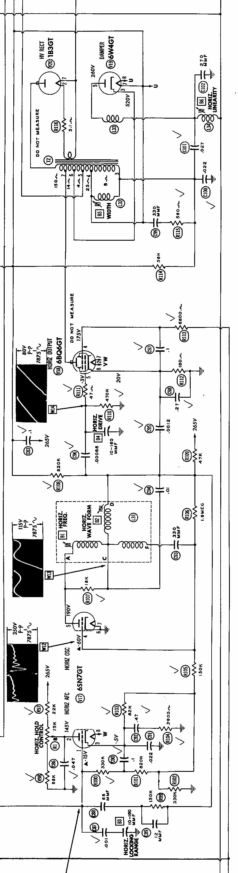
Guided by further email from Bill, I investigated several things in the horizontal circuitry, including the level of "B+ boost" voltage. To eliminate possible trouble sources, I replaced every resistor in the horizontal oscillator and output circuits. I also tested associated coils, such as the width coil, in case they had opened. To help Bill understand the problem, I scanned the
horizontal portion of the TV schematic and posted it on my website. On the schematic, I checked off the components that I had replaced up to that point.
Nothing seemed to make a bit of difference, and I was running out of things to check.
Back to the Future!
Lacking fresh ideas, I decided to remove and test all the capacitors that I had replaced in the horizontal circuits. I normally test every new component before installing it. Every once in a while, however, a "factory fresh" capacitor will be bad, and I had eliminated everything else in the horizontal circuits from the equation.
I started with the two small capacitors I had fashioned to replace the two black beauties. On the schematic, these are marked C95 (.0012 mfd) and C96 (.0068 mfd). Before replacing these, I turned the horizontal frequency adjuster to the middle of its range.
Lacking any other caps of the right value, I pawed through my bag of replaced components and found the original black beauties that I had pulled out days earlier. Substituting C96 had no effect, but installing the original C95 (.0012) capacitor immediately destroyed all vestige of horizontal sync. The original capacitor was clearly defective.
Because C95 and C96 were such small values, I had replaced them with tiny ceramic disc capacitors rather than orange drops. In hindsight, this had been a mistake. As I learned from Bill, ceramic discs are a poor choice for frequency-critical applications. They are easy to damage when you solder them in. They can also change value as the set heats up.
Time for a new (and better) replacement! Digging deep into my collection of orange drop capacitors, I found two that would equal .0012 mfd when wired in parallel. After soldering them together, I tested the value on my capacitor checker to confirm that it was correct. Then I installed the replacement and fired up the TV. The picture immediately locked on the horizontal and remained stable. This nagging problem was finally solved!
On the Home Stretch
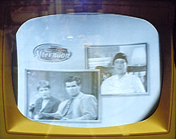
The remaining glitches were easy to correct. The next photo shows the picture at this stage. (The real picture was not as blurry as this one looks. It's hard to take a sharp photo of a live TV screen unless the image is completely still while the camera's shutter is open.)
The horizontal width was still insufficient, leaving black bars on each edge. The vertical linearity needed another touchup, as well. In this photo, the top of the woman's head appears stretched and you can see little spaces between the scan lines at the top. This requires a linearity adjustment to make the top half and bottom half of the picture equal in height.
I improved the horizontal shrinkage problem by carefully twiddling the horizontal controls on the rear of the chassis. The next photo shows the picture at this stage.
The picture was definitely wider, but it looked slightly offset to the right. An oval black area had appeared in the lower right corner. The picture was also slightly tilted off the horizontal, although it's hard to tell from this small photo.
Bill Sheppard offered the following advice:
Leveling the picture is done by rotating the yoke itself.
There's usually one or two setscrews to loosen for this.
A magnetic ring or pair of rings on the back of the yoke
(if present) is for centering the picture.

Dark area in one corner: the ion trap magnet (if used) is
adjusted for maximum brightness of the raster consistent
with no shadow areas. It's the little doohicky that sits
directly astride the gun in the back of the CRT. The
centering ring(s) also affects shadow areas, and "juggling"
with the ion trap adjustment is sometimes needed.
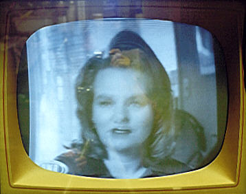
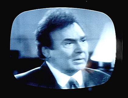
Once again, Bill was right on the money. The mechanical adjusters on the picture tube neck quickly eliminated these defects. The next photo shows the result.
Although this photo is not extremely sharp (why can't those actors stand still!), the picture is level, with no unnaturally dark areas, and it fills the entire screen. Compared to where we started, this was a huge improvement.
It Ain't Over Until . . .
Now that the gross video problems had been solved, I spent some time watching the TV on different channels and evaluating its performance. Although I could get watchable video and audio on every channel, I almost always had to adjust the fine tuning when switching to a new channel.
Earlier, another member of rec.antiques.radio+phono had advised me to adjust the "hidden" fine tuning screws within the tuner itself. On this set, these adjusters are accessible from the front of the "outrigger" tuner box. As you switch to each channel, a small hole opens up to expose a tiny adjuster screw deep inside the tuner mechanism. That sounded easy enough, but I still had no way to reach them with the TV installed in the cabinet!
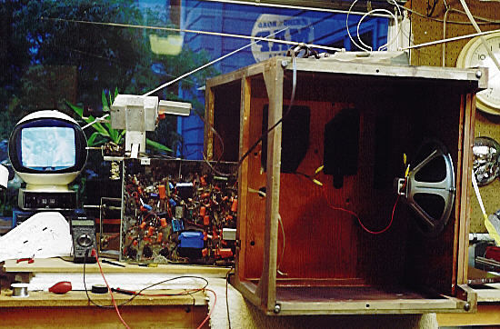
The following photo shows the solution.
Yes, that's the console cabinet lying sideways on my workbench, padded by a piece of carpet. Let me tell you, it took a mighty hoist (and help from my wife!) to get that cabinet with its heavy CRT onto the bench.
Through email exchanges with Bill and others, I learned how professional repairmen got access to TV chassis like this. A well-appointed workbench would be mounted with a spare speaker and generic CRT, with long cables to connect everything to the chassis. Extender cables could also be used to connect the chassis to the CRT while standing behind the cabinet, similar to the setup shown above.
Some TVs even had access holes cut into the cabinet bottom, permitting access to the chassis for anyone willing to lie on his back. My cabinet actually has such access holes, I discovered too late to do me any good. The holes are covered with a ventilated metal plate. If you remove the plate and reinstall the chassis, you can reach parts of the chassis, although you have to be a real octopus to work very long in such a contorted position.
In any case, I found that the CRT and yoke cables would reach the chassis if I stood the chassis on its side and positioned it just so. I connected a jumper cable from chassis ground to the CRT frame and fashioned a temporary extender cable for the high-voltage lead to the picture tube. (I was very careful to insulate the h-v lead connections with electrical tape and to keep the lead well away from the chassis.) Jumpers were also extended to the speaker leads.
The arrangement was cumbersome, but, with the aid of my trusty mirror, I was able to touch up the fine tuning. That concluded
the restoration.
About two years after finishing this project, the horizontal
hold again went out. Discouraged, I moved the TV back out to
my workshop where it sat for a long time, as I got involved
in other projects. I eventually gave it away to a fellow
collector who was interested in tinkering with it.
Having spent so many hours wrestling with this monster, I
had lost all motivation for a rematch!
P.S. Special thanks to Bill Sheppard for putting up with my novice questions and offering lots of additional advice besides what appears on this page.
|