RCA Model 8-X-541 Bakelite Radio (1948)


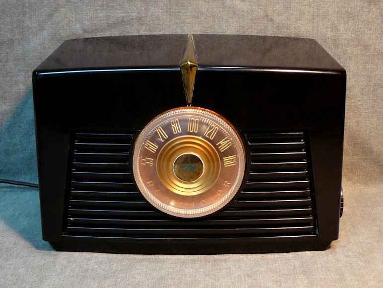
The simplicity of this design gives it a timeless appeal. With a large gold dial in a
streamlined Machine Age cabinet, the RCA 8-X-541 proves that beautiful design doesn't require
excessive ornamentation.
Here is the restored radio:
Description
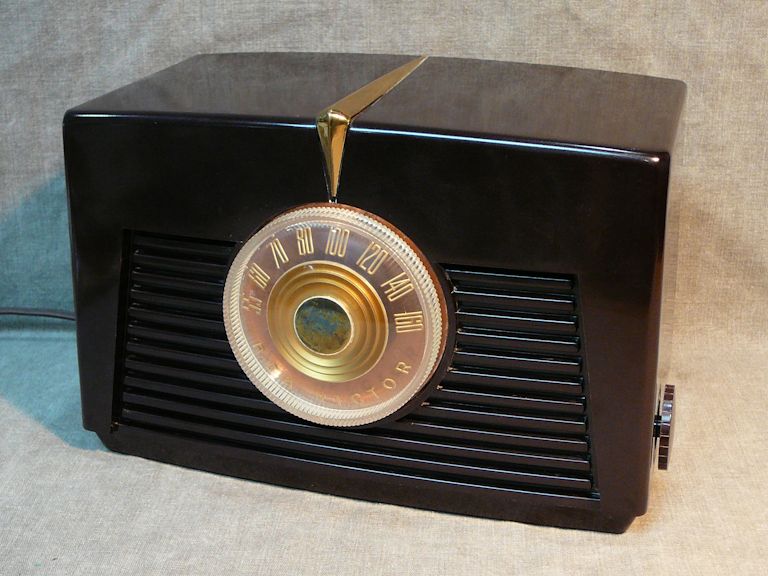
The RCA 8-X-541 is a classic "All American Five" tabletop radio and RCA produced
it with a few color variations.
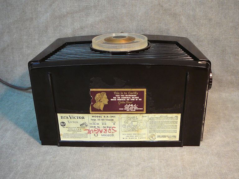
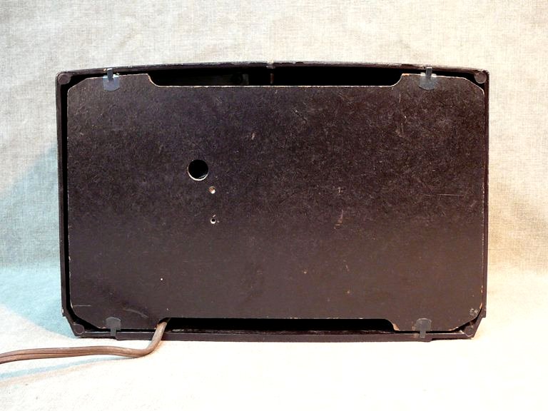
My 8-X-541 has a brown Bakelite cabinet; I believe that
some of this model were also painted a dark maroon color. The identifying label is
on the bottom and the rear cover is held on with four spring clips:

Models 8-X-542 and 8-X-547 look like the same radio with a red and gold dial and
an ivory or white painted cabinet. There were also some minor electronic differences.
You can find the schematic for these
models at the Nostalgia Air website.
Finding an RCA 8-X-541
I owned this radio for so long that I can't remember where I bought it! Judging by my
website records, I got it before I launched this website nearly 20 years ago.
For most of that time, it remained as a "shelf queen" in my collection—a
set that looks great on display but hasn't been restored electronically.
In 2015, I was contacted by a collector who had owned one exactly like it as a boy.
He remembered sneaking the radio under the blankets late at night to listen to distant
stations. When he asked to purchase it, I decided to restore the electronics and pass
the set along to a new owner.
Restoration
Restoring the electronics was a straightforward task. Although I didn't expect much
from an unrestored sixty-seven year old radio, I cautiously powered it up, watching for
danger signs and using my metered variac to monitor its power consumption.
To my surprise, it played normally.
Still, with any radio of this vintage, it's prudent to replace its
capacitors to ensure safe, reliable service.
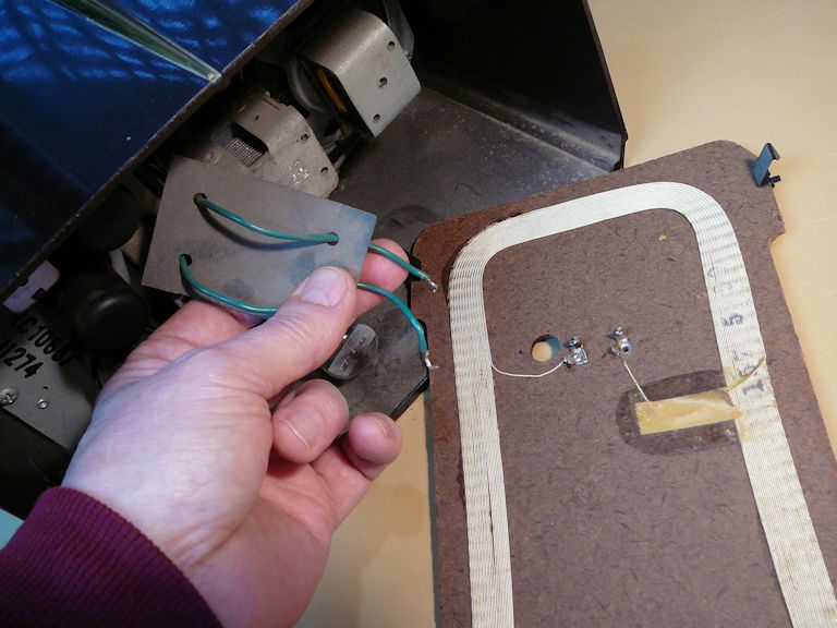
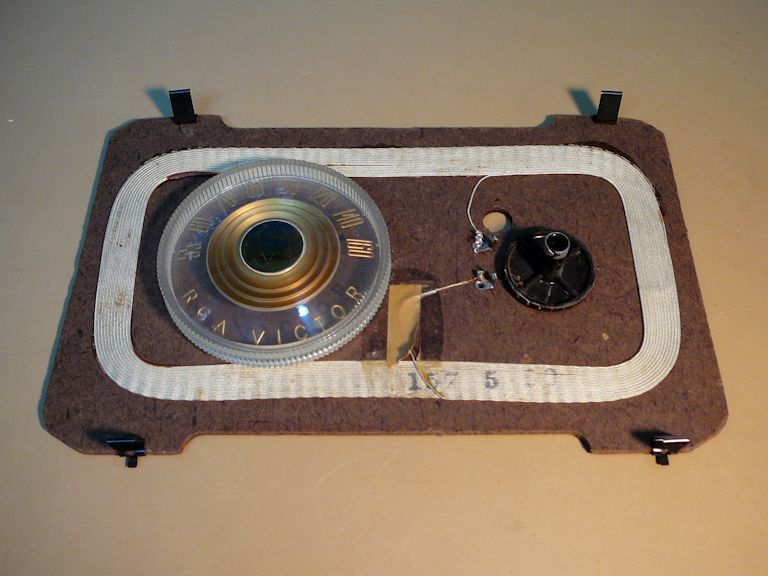
The first step is to remove the radio's knobs and unsolder the wires leading to the
built-in loop antenna mounted inside the back cover.


While the big tuning dial came off readily, the small power/volume knob had been stuck firmly on its shaft.
To avoid breaking the knob, I warmed it carefully with a heat gun and tried again. The heat expanded
the knob just enough that I was able to gradually pull and wiggle it off the shaft.
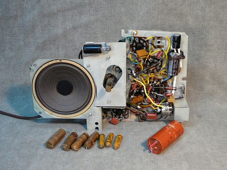
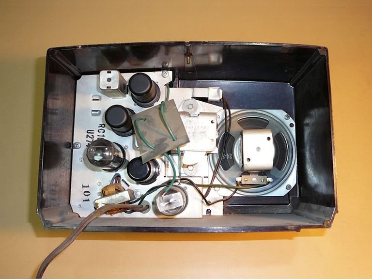
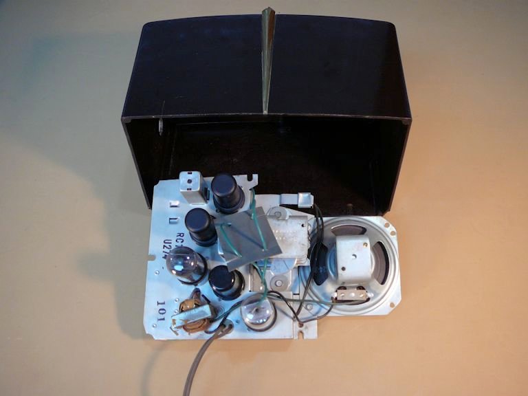
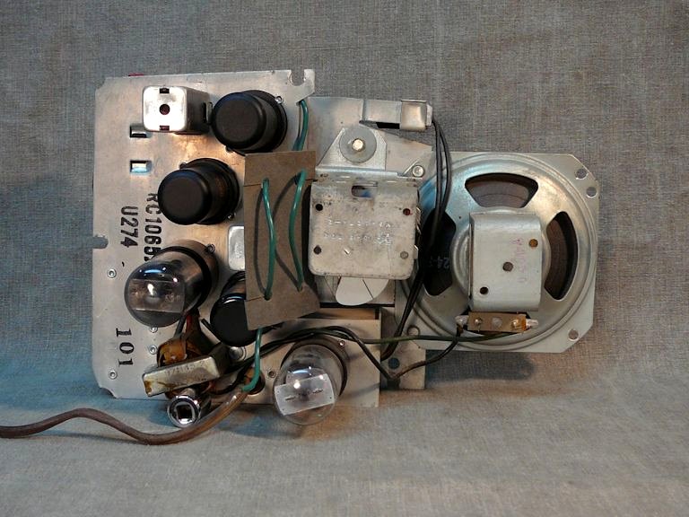
The next photos show the chassis mounted inside the cabinet and immediately after
I removed it. The chassis and its speaker come out as a single unit after
you remove the five mounting screws:


In many tabletop radios, the chassis lies flat on the bottom of the cabinet
and the tubes stand upright. In this one, the chassis is mounted against
the cabinet front and the tubes extend horizontally. This was done to facilitate the
big round dial on the front, as will be seen in the following photos of the unrestored chassis.


The first photo shows the chubby brass shaft for the tuning dial right in the center of the chassis.
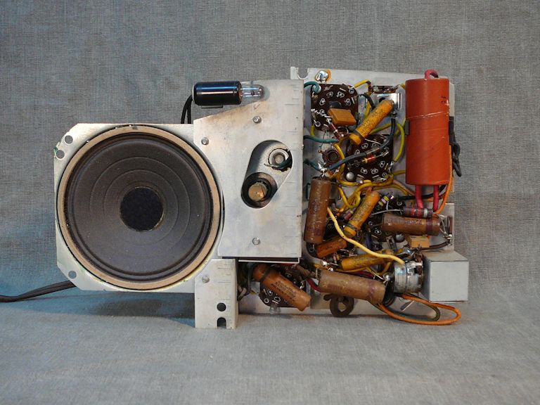
In the second shot, you can see that the tuning capacitor sits right behind
that shaft. The dial drives the tuning capacitor directly, rather than with a string
and pulley as in most radios of this sort.
Eliminating the string-and-pulley mechanism enabled that big, beautiful dial on
the front and it probably saved a little expense, too. This is also a low-maintenance
mechanism, with no string that might break and very few places needing lubrication.
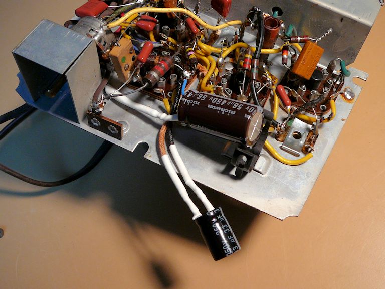
The first photo above also shows the nine capacitors that I'll replace: seven paper capacitors
and two electrolytics contained in a fat cardboard cylinder.
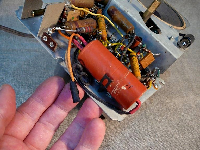
Examining that electrolytic container explained why the radio had played so well in
my initial test. This one is a replacement, probably from the 1960s or even later.

The previous repairman soldered the new capacitor leads to the old wires
and covered the junctions with electrical tape. Not the prettiest repair that I've ever
seen, but it worked. Since he had left the old leads their original length, I was
able to connect the replacement capacitors quite easily.


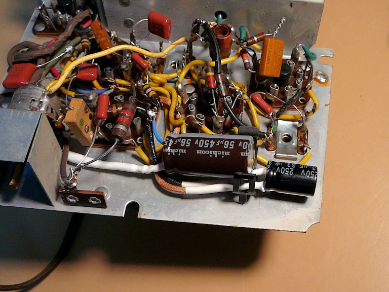
The new electrolytics fit neatly into the space where the old one sat. There is no
need to enclose them in a tube or anything else, as long as their leads are well insulated. I'll strap
them to the old metal clip to make sure they can't wobble around.
Here are before-and-after photos showing the replaced capacitors:
I re-tested the radio after recapping, and it sounded better than ever, with strong
reception and a clear tone. Before putting it back into the cabinet, I cleaned the
controls and lubricated the tuning capacitor. You can read more about such basic steps
in my article, First Steps in Restoration.
I also replaced the little lamp (a type 47) that illuminates the tuning dial.
Final Thoughts
With that, my restoration was complete and I packed up the radio to ship to its new owner.
If you are looking for a radio to take on as a first restoration project, this model would be a sensible
candidate. Its "all in one" chassis is very easy to remove and to handle
on the workbench. Its electronics are simple, unlike complex radios that also receive
shortwave or FM; and its capacitors and other components are easy to reach.
It was satisfying to complete this job after letting the radio sit unused for so long. If I
start to miss this little guy, I can probably find another one without much difficulty. It's a beautiful
set, but not particularly scarce. RCA must have sold many of them back in 1948, judging by how
many have survived.
|