RCA Radiola Model III Radio (1924)


The RCA Radiola Model III was introduced in 1924. Priced at $24.50, it became very
popular and sold in the thousands. Many of them survive today, so if you are just getting
interested in 1920s radios, this is an affordable choice. It should not be hard to find a
nice one for $100 or even less.
Description
The Radiola III is a battery-powered regenerative type receiver, using two
type WD-11 tubes. One tube acts as the detector, the other as an audio amplifier.
It receives frequencies from
470-1540 kilohertz, approximately the same as our modern standard broadcast band.
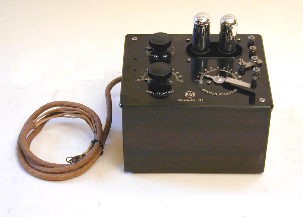
This is a small radio. Its cabinet is almost cube-shaped, measuring about 8 inches wide, 7
inches deep, and 7 inches high (including the height of the tubes). The thick cloth cable coiled
to the left contains the battery wires.
The cabinet is made of solid mahogany. Most are dark brown, finished with lacquer. A few
were painted black.
The faceplate and large knobs are made of black
Bakelite. Other controls and fittings on the faceplate are nickel plated. The
next photo shows the controls more clearly.
Like many radios of the time, the Radiola III was designed for use with headphones.
To the left of the faceplate you can see two small holes where the headset would be
plugged in.
RCA also sold a Model III-A, which was larger and more expensive than Model III.
It used four tubes rather than two, with enough amplification to connect a
loudspeaker rather than headphones.
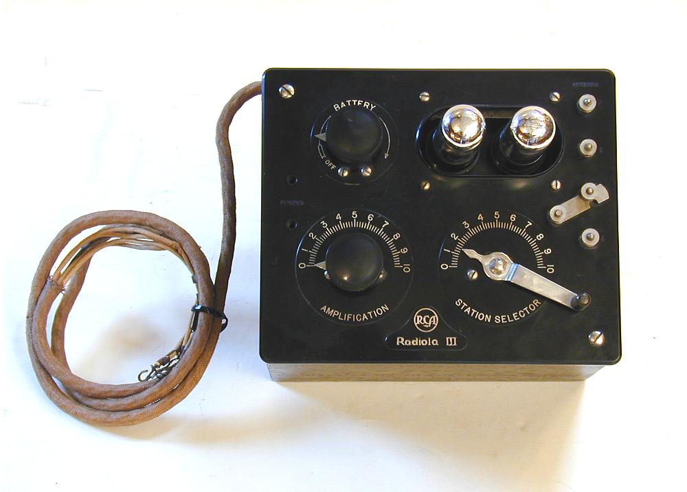
Controls
The controls will look unfamiliar to modern radio users, so let's explain them.
The Station Selector lever
on lower right is not hard to figure out. It selects the desired frequency, just like
a modern tuning knob, but, typical of this era, its dial is marked with a simple 0-10
scale rather than frequency numbers. Users of the time would keep a "station log,"
or record of which stations could be received at a given selector setting. (More on
this type of scale later.)
The Battery control increases the voltage supplied to the tubes as you turn the knob to the
right. This lets you compensate for a battery's lower output as it drains over time. When
you turn Battery to Off, the radio is turned off.
The Amplification knob is not like a modern volume control. A better name might have been
Regeneration.
The Radiola III is a "regenerative" type receiver, using
controlled feedback to amplify the signal.
If the degree of regeneration is too low, the signal is
weak. If it is too high, you hear distortion or even
a loud "feedback" howl. When tuning in a
station on this radio, you set the Amplification control to a point just below where the distortion begins.
Invented by Edwin Armstrong, the regenerative circuit was the first high-performance
design for tube radios. Armstrong was a pivotal figure in radio development. He later invented an
even better circuit—the superheterodyne—which became
the standard even to this day, as well as FM radio.
Antenna Connections
On the right of the faceplate are four antenna terminals, numbered 1-4, with a solid link that can be used
to connect terminals 3 and 4. By connecting your antenna to these terminals in different ways, you can
change the frequency range that the radio can receive and also affect its sensitivity and selectivity.
The following diagram from the Radiola III owner's manual shows
six different antenna configurations. (Note that "short wave" in the diagram does not mean shortwave
frequencies in the modern sense. It refers to a range within the standard broadcast band
with shorter waves than other possible ranges.)
Here is how the owner's manual explains the various connections, numbered as given in the diagram:
|
1.
|
Antenna on 4, link open. This is a single circuit connection which on an average antenna
will cover the approximate wavelength range of 200-360 meters corresponding to a frequency
range of 830-1500 kilocycles (kilohertz).
|
|
2.
|
Antenna on 3, link open. This is a single circuit connection which on an average antenna
will cover the approximate wavelength range of 250-480 meters corresponding to a frequency
range of 625-1200 kilocycles.
|
|
3.
|
Antenna on 2 and 3, link open. This is a single circuit connection which on an average antenna
will cover the approximate wavelength range of 315-560 meters corresponding to a frequency
range of 535-950 kilocycles.
|
|
4.
|
Antenna on 2 and 3, link on 4. This is a closed single circuit which on a very small antenna,
such as an indoor one,
will cover the approximate wavelength range of 290-575 meters corresponding to a frequency
range of 520-1070 kilocycles.
|
|
5.
|
Antenna on 1, link on 4. This is a selective single circuit connection which on an average antenna
will cover the approximate wavelength range of 195-375 meters corresponding to a frequency
range of 800-1540 kilocycles.
|
|
6.
|
Antenna on 1, link on 3. This is a selective single circuit connection which on an average antenna
will cover the approximate wavelength range of 310-640 meters corresponding to a frequency
range of 470-970 kilocycles.
|
When the antenna instructions refer to an "average antenna," that means an outdoor antenna
at least 50 feet long.
If the antenna connection scheme sounds a bit confusing and inconvenient, you're not alone.
Shortly after the Radiola III was introduced, a company named Barklew produced an aftermarket
switch which allowed you to quickly change the antenna configurations without manually
disconnecting and reconnecting wires to the antenna terminals.
Now that you have learned about antenna connections, you can understand why the Station Selector dial
does not show frequency markings, as we noticed earlier. A given station will appear at different
spots on the Selector dial, depending on how you have connected the antenna.
A Radiola III owner
would record in the station log exactly how to tune in a given station. For example, to dial in
KIRO radio at 710 kilocycles, you might note something like,
"antenna configuration 2, Station Selector = 3.4."
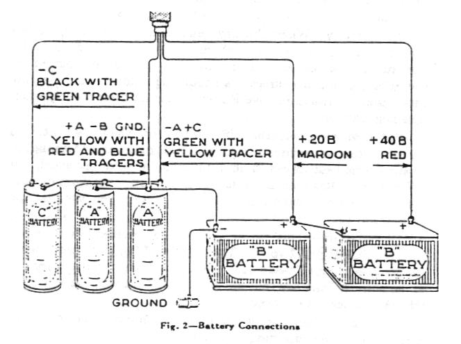
Battery Connections
The Radiola III requires three batteries, designated as A, B, and C in the convention of the time.
The A battery (1.5 volts) is used to heat the tube filaments, causing them to "turn on."
The B battery (90 volts) supplies high voltage to the tube plates. The C battery (4.5 volts)
supplies a low voltage to create a negative charge (bias) for the tube grids.
This RCA diagram shows a typical battery hookup of the time.
In this diagram the two B batteries are
45-volt cells, which, connected in series, provide 90 volts. If you are
using modern batteries, you can use ten 9-volt "transistor"
batteries, connected together with standard battery clips, to supply
the B voltage. A modern D cell ("flashlight battery") can be
used to supply 1.5 volts for the A supply. You need 4.5 volts for the
C supply, which can be provided by three modern AA cells connected in series.
The Radiola III battery wires have little metal tags on the ends, with stamped
labels corresponding to the labels used in the battery diagram and schematic. This is
very helpful if the colors on your wires have faded, as mine have.
Some people prefer to use an AC adapter rather than batteries. Our
battery replacement article gives plans for making
an inexpensive adapter. You can also buy ready-made adapters from sources
such as Antique Electronic Supply.
Electronics
The electronics inside a Radiola III look very different than modern radios.
Here is one view of the radio's internals.
The round bracelet-shaped component at lower left in this view is the
Battery control—a variable resistor, or potentiometer in modern
parlance. The black transformer above the
little metal cage is the audio output transformer. Inside the cage (below
the transformer) are sockets for the radio's tubes, which were removed
for this photo.
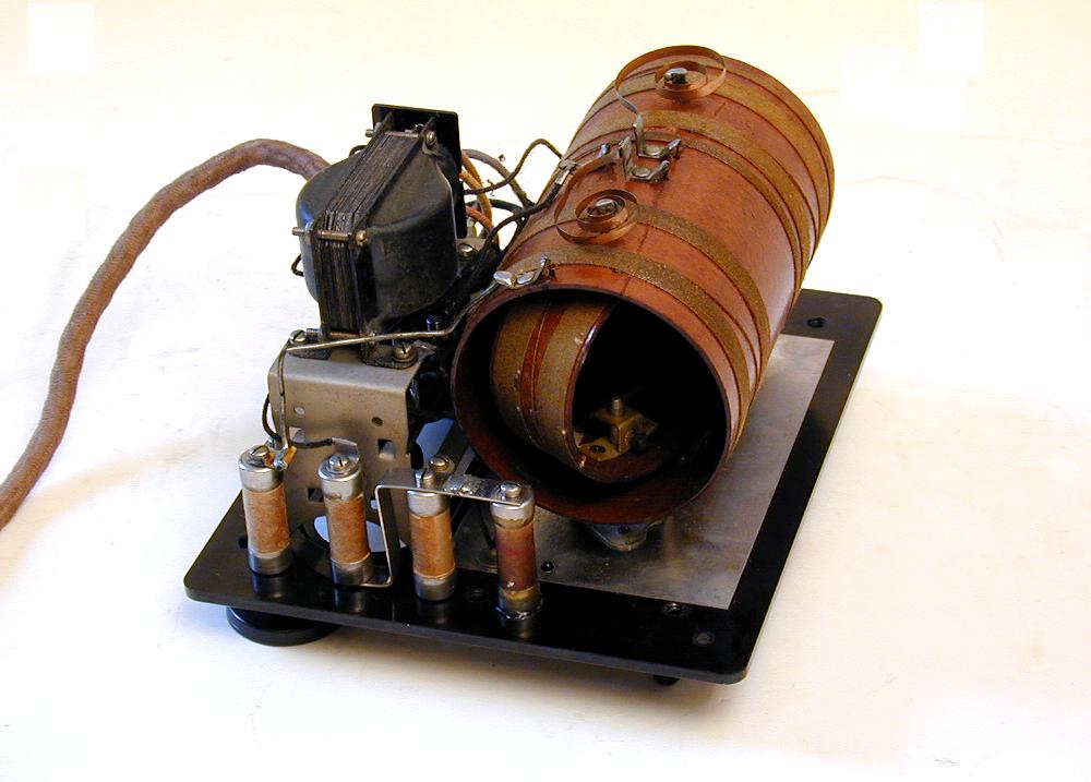
The next photo gives a slightly different view.
Note the four tube-shaped components. These are capacitors, connected
to each of the four antenna terminals on the faceplate.
The large brown coil-shaped component is a "variometer," or
variable inductor. Inside the large barrel-shaped coil you can see a smaller
coil, which rotates as you turn the Station Selector control. In
the other end of the variometer is a second inner coil, which
rotates as you turn the Amplification (regeneration) control.
The watchspring-shaped metal pieces on top provide connections between the
shafts of the rotating coils and the rest of the radio. They coil and uncoil as you turn
the Station Selector or Amplification knob. Some Radiolas used ordinary cloth-covered wires instead of springs.
Since the wire would eventually fray or break from use, the spring was a better solution.
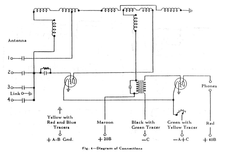
Below is the Radiola III schematic diagram.
This radio has so few components that it's easy to identify everything.
On the left are antenna connectors 1-4, with a capacitor connected
to each terminal. The coils on the top comprise the variometer. The transformer
shown near the bottom is the audio output transformer, and the circular
components are the tubes. Battery connections are also shown along the bottom.
This schematic shows a component which is not present in my Radiola. In between
antenna terminal 2 and the first tube is a resistor/capacitor combination known
as a "grid leak" detector. Some Radiolas have this, others don't.
When present, it is a tube-shaped component that looks like the four tubular
capacitors seen in the earlier chassis photos.
Radiola III Tubes
Sharp-eyed Radiola III fans probably noticed that my radio does not have
the type of tube (WD-11) originally supplied with this radio. What's going on?
The WD-11 tubes used in the Radiola were produced for only a short time, quickly
being superseded by newer types such as the UX-199. WD-11s were also very fragile,
so many of them failed and were discarded.
If you can find a working WD-11 nowadays, it will be very expensive—anywhere
from $75-$150—and most collectors would not even play it in a radio, for fear
of burning it out.
While the WD-11 was still in production, RCA issued service bulletins showing how to convert the
Radiola III to use newer, higher-performance tubes, such as the UX-199.
My radio was fitted with
such a conversion, and it uses UX-199 tubes rather than WD-11s. Since the tube adapter itself is
a vintage item, possibly only a year or two newer than the radio itself,
I don't mind keeping it.
You can learn about making a modern adapter in this discussion
from the Antique Radio Forum.
Like other regenerative radios, the Radiola III is sensitive to microphonics, which are
self-sustaining oscillations inside a tube which can start if the tube is rapped
or jiggled. When a tube goes into microphonics, you will hear a very high-pitched
squeal or ringing sound.
To alleviate this, the Radiola's tube sockets are mounted
with rubber shock absorbers. Like many other 80-year old rubber products, the original
shock absorbers may be deteriorated, but it's not hard to find replacements. Use care
when replacing tubes, to avoid damaging the shock absorbers.
Final Thoughts
This was my very first 1920s radio, so becoming familiar with it was quite an
adventure in learning. If you are used to working on newer radios, it's impressive
that such a radio can get good performance using so few components.
As with every regenerative radio, tuning in a station requires more fiddling than
simply twisting one knob. You may need to change your antenna
connection to receive a station at a particular frequency, and tuning in the station will
often involve adjusting Amplification as well as
the Station Selector.
Some station signals are stronger than others, as we all
know. Modern radios have a circuit called AVC (automatic volume control) which
automatically compensates for this. As you spin the tuning dial, AVC turns down the
volume for very strong stations, so that you ears aren't blasted off when you
switch from a weak, distant station to a strong, local one.
A simple radio such as this has no AVC, so you will need to manually tweak the
Amplification control, choosing the best setting for volume
and fidelity, without distortion.
That's all part of the fun for a 1920s radio lover, however. It can be a real blast to
use a radio as old as this one. You may be pleasantly surprised at how good it sounds!
|