Hallicrafters Clear Lucite Clock Radio (1952)


This unusual radio in a clear lucite cabinet was never sold to the public.
Designed to show off Hallicrafters' printed circuit technology, it was offered
only to dealers as a display piece. If the dealer purchased a special promotional
package of several radios, this one was included at no cost.
I was fortunate to find one in
near-perfect condition, with no chips, cracks or scratches.
Apart from some dust and fingerprints, it looked just as when it was
built in 1952.
Description
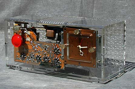
The thick lucite cabinet is striking, to say the least. The first photo shows the radio on my messy workbench,
shortly after I unpacked it.
The cabinet is constructed of four pieces held together with a number of tiny screws.
The top, front, and bottom are formed from a single lucite sheet bent into a
channel shape. The back is another large sheet, drilled with many ventilation
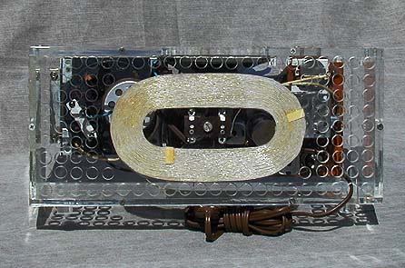
holes and holding the built-in loop antenna. Two squarish panels close off the sides
and four cylindrical feet are glued to the bottom, to complete the cabinet.
Unlike most radios, this one has no paper labels or model designation. You wouldn't want
to spoil the "invisible cabinet" effect!
The Sessions clock movement is mounted on the right. The clear volume control and red tuning control
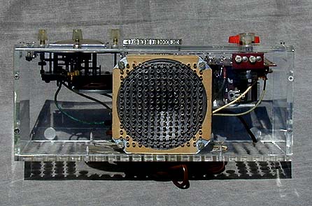
appear on the left. The speaker is mounted on the top, which is drilled with 616 tiny
holes to form a grille opening. Most of the visible front area is occupied by the sideways-mounted
circuit board. The chassis is suspended from the top of the
cabinet, held in place by two screws over the volume control.
Glued to the front of the cabinet in the center is a silver plastic logo
that says Hallicrafters, precision built. The dial numbers are painted in
white on the front of the plastic case. If you ever clean up one of these sets,
be very cautious around those dial numbers. They look pretty fragile to me.
The next photo shows the radio on the day after purchase. At this point, I had taken
out the chassis, speaker, and clock, and lovingly polished the lucite cabinet pieces.
As you can see, the clear cabinet standing alone is practically invisible!
Like many clock radios, this one is a little fussy to disassemble. All of the internal
components are hard-wired together. You need to
avoid tearing wires loose during disassembly or dropping the clock, which
could bend its fragile hands. You also need to avoid scratching the inside of
the cabinet, which is just as visible as the outside.
Electronic Restoration
The previous owner had sent the speaker to a professional reconing shop, so
the speaker was in fine shape. Upward-mounted speakers like this tend to
accumulate lots of dust over the years. After I finish restoring this radio,
I may lay a little square of clear plastic over the speaker when not in use, to
prevent this problem.
To radio shoppers of 1952, this radio must have looked pretty miraculous. In addition
to the revolutionary printed circuit, it seems
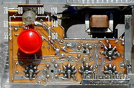
to be missing most of its small capacitors and resistors. The next photo shows the top of
the chassis, on which only two resistors and two capacitors are visible.
The secret to this simplified design is a small, flat component in a ceramic case. If you look very carefully
at the previous photo, you may spot it mounted just to the right of a metal shield that
separates the two leftmost tubes from the other tubes. The slim case contains
several small capacitors and resistors, which would have been hand-wired in older designs.
This early type of integrated circuit is also found in my Majestic 5LA5
and Coronado 8154 tabletops. If you read my
Philco Predicta television
article, you can see how I reproduced such a component, which Philco
referred to as a couplate.
According to the Hallicrafters collector guide, this radio is electronically identical
to the ATCL series clock radios. I don't have an ATCL schematic, but both radios
do share the same five-tube lineup: 12BE6 oscillator/mixer, 12BA6 IF amplifier,
12AV6 detector/AVC/1st audio, 50C5 output, and 35W4 rectifier. Like the ATCL series,
this radio covers only the standard broadcast band, from 550 to 1600 khz.
Although the clock worked fine, the radio was not playable when purchased. As the
next photo shows, there was evidence of overheating on the upper right of the
circuit board, around the 50C5 output tube and 35W4 rectifier tube.
Testing revealed that the 50C5 output tube was dead.
That can be caused by failure of the power supply filter capacitors,
a very common problem in old radios.
In an ordinary radio of this type, I would simply
disconnect the old filter capacitor and wire new caps out of sight under the chassis,
leaving the old can in place for appearance.
In a clear radio, however, there is no "out of sight" place in which to hide new components!
If I wanted to preserve the original appearance, I would have to find either an
exact replacement can or two new capacitors small enough to fit inside the old can.
An appeal to the rec.antiques.radio+phono newsgroup
revealed sources for both solutions. A friendly fellow collector searched his
stores and found an exact replacement, which he sold me for $1 plus postage.
Another collector informed me that Nichicon brand axial capacitors,
available from Antique Electronic Supply,
are small enough to fit inside the old can.
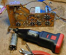
Removing the old can was a tedious job.
It was soldered to the circuit board in five places, with two lugs for
the two capacitor hot leads and three lugs securing the can itself, which serves
as the common negative point for both capacitors.
Before loosening the can, I heated each lug and used a solder sucker to remove as much
solder as possible from the joint. Using a Dremel tool, I cut each
lug close to the board. Then, taking care not to damage the board, I inserted
a thin screwdriver blade between the can and the top of the circuit board. Heating each lug
in turn, I gently levered the can up at that point, then moved on to the next lug. It
took several minutes, but I finally freed all five lugs bit by bit, and the can came free.
The next photo shows the chassis at this stage.
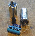
The next photo shows the new and old cans, along with some potential replacements.
The big blue capacitor in the front is a 47 mfd unit, which has the right electrical
characteristics but is too large to fit in the can along with another 33 mfd unit
of similar size. Behind it are two smaller Nichicon capacitors which would fit if
I had needed to "restuff" the old can.
Soldering the new can in place took no time at all, compared to the chore of removing the old one.
Removal had torn off a couple of bits of foil around the attachment points. To restore
the original appearance, I tacked bits of very thin wire into the blank spots. When solder
from the joint was flowed onto them, everything looked just like new.
I also decided to restuff the two original paper capacitors
for reliability's sake. Restuffing a wax paper capacitor usually involves heating
it in an oven to melt the wax, then pulling out the insides with a pliers. I tried
that with the first paper cap, but it refused to melt! As I discovered when I unlimbered
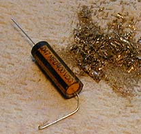
my drill, the insides were actually hard plastic. The next photo shows the old
capacitor next to the replacement unit. Most of the interior
of the old cap has been drilled out.
The following photo shows the new capacitor snug within the old case. The final
touch was to smooth off both ends with hot glue, then color them black with
a Sharpie marking pen. When I was done, the capacitor looked exactly as it had
before, only with new insides.
Before reinstalling the chassis in the cabinet, I spent quite a bit of time cleaning
the circuit board. Most of the cleaning was done with Q-tips and lacquer thinner, which
dissolves gunk and soldering rosin, leaving the board shiny. I used a soft brass brush
on the Dremel tool to dislodge stubborn gunk around the tube sockets.
I also spent a few minutes cleaning other visible metal components, such as the
tuning capacitor frame, transformer cans, and volume control case. When every bit
of the chassis is on perpetual display, it's worth taking time to spiff up things
that would not otherwise merit such loving attention.
After reassembling the radio, I brought it out into the sunshine for a final
photo shoot. It's surprisingly difficult to capture the true beauty of this
clear cabinet. Perhaps on some rainy winter day, I'll try some more photos
using floodlights against a dark background. In the meantime, these shots
will have to do.
|