|

Build a Crystal Shortwave Radio
This project combines two popular themes from radio history—crystal radios and shortwave (SW) listening. It's designed from scratch by our non-resident engineer Walter Heskes.
Despite all of the advances in modern electronics, there are thousands of crystal sets in daily use throughout the world. The fidelity of tone and clarity of crystal rectification are hard to beat. What's more, crystal sets are absolutely free! A crystal receiver is powered solely by the radio waves that it pulls from the air.
We dubbed this inexpensive radio the "EconOceanic" in honor of the legendary Zenith TransOceanic family of shortwave radios. It tunes the AM broadcast band, from .5 MHz to 1.6 MHz, and most of the shortwave band, from 1.7 MHz up to about 17 MHz.
There's plenty of SW activity in these bands, so you'll hear lots of different voices, a mix of languages, and even music. In addition to powerhouse stations such as the BBC, you'll also hear non-commercial amateurs, some of whom broadcast using the dits and dahs of International Morse Code. And don't forget to set your wristwatch by the precise WWV time signals. They appear at exact multiples of 5.0 MHz across the SW bands. Listen for the calibration beeps and periodic time announcements.
We hope you enjoy this project. If you build an EconOceanic, send some email to let us know how it worked out. Walter can be reached at walterh@interworld.com.
Building Instructions
You're eager to start assembly, but a few minutes of preparation will
help this project go smoothly. Here's how to get started.
Printing Instructions
Before you lay hands on any parts, print out this page and all of the diagrams in the following table.
The large diagrams are designed
to print on a standard 8.5 x 11-inch sheet of paper. Most of them are
oriented horizontally for easier reading online. Choose your printer's
"landscape" mode for the horizontal diagrams, to make sure they'll print
on one sheet. Be sure that your printer is set to print at a 1-to-1 ratio,
so that the cabinet decal and layout diagram are the correct size.
Parts and Tools
We recommend getting all of the parts you need before you start
assembly. Nothing is more frustrating than getting halfway
through a project, then having to wait several days for some
missing part to arrive in the mail.
The following parts list gives part numbers and sources
for all major parts, plus some notes on particular items.
Most of the parts you need to build the EconOceanic Crystal
Shortwave Receiver are available through Radio Shack. Two exceptions
are the big tuning capacitor and the little trimmer capacitor.
The big tuning capacitor can be obtained from Antique Electronic Supply. Or,
you may be lucky enough to have a spare tuning capacitor in your junkbox.
The small trimmer capacitor is available from All Electronics,
allcorp@allcorp.com, 1-800-826-5432. Some notes on specific parts appear after this list.
| Quantity |
Component |
Type |
Part No. |
Price |
| 1 | Diode | 1N34A 1 | Radio Shack 276-1123 | $ 1.19 pkg 10 |
| 1 | Variable capacitor 2 | Dual-range: 40-460 pF/30-156 pF | AES CV300-145 | $3.50 |
| 1 | Trimmer capacitor | 6-40pF | All Elect. VCAP-14 | $1.50 |
| 1 | Ceramic capacitors 3 | 10 pF, 22 pF, 50 pF | Radio Shack 272-801 | $2.49 pkg 100 |
| 2 | Phone jacks | 1/8-inch diameter | Radio Shack 274-251 | $2.49 pkg 3 |
| 1 | Speaker terminal strip 4 | Spring-loaded | Radio Shack 274-315 | $ 1.29 |
| 4 | Rotary switches | 2-pole, 6-circuit | Radio Shack 275-1386 | $1.69 |
| 1 | Slide switch | DPDT | Radio Shack 275-407 | $ 1.29 pkg 2 |
| 1 | Enameled wire 5 | #22 and #26 | Radio Shack 278-1345 | $3.99 pkg 3 |
| 3 | Knobs | 1.0-inch diameter | Radio Shack 274-416 | $2.29 pkg 4 |
| 2 | Knobs | 0.75-inch diameter | Radio Shack 274-415 | $ 1.89 pkg 4 |
| 1 | Project box | 7.5" x 4.33" x 2.22" plastic | Radio Shack 270-224 | $ 3.49 |
| 1 | Cardboard tube | From paper towel roll | | |
| 1 | Epoxy glue 6 | JB Weld or similar | | |
| 1 | Household glue 7 | Elmer's Glueall or similar | | |
| 1 | Rubber feet 8 | Heavy-duty self-stick | Radio Shack 64-2342 | $ 1.49 pkg 8 |
| Optional | | | | |
| 1 | Amplified speaker 9 | Battery powered | Radio Shack 277-1008 | $11.99 |
| 1 | Headphones | 2,000-ohm | AES P-A466 | $14.50 |
| 1 | Antenna | 6-foot telescoping | Radio Shack 270-1408B | $4.99 |
| 1 | Fuse holder clips 10 | (for antenna swivel) | Radio Shack 270-739A | $ 1.19 pkg 2 |
Notes
1 Any type of germanium diode will work.
2 A variable air capacitor can be scrounged from any old AC/DC superheterodyne AM radio. Use the RF section for the wide range (40-460 pF) and the oscillator section for
the narrow range (30-156 pF)
3 Bags of ceramic capacitors are available in large quantities from Antique Electronic Supply and Radio Shack. These capacitors will work fine, but if you buy them in bulk, you may need to identify them using their markings or by reading them with a capacitor meter.
4 The speaker terminal strip is used for the ground and antenna connections, as explained in the building instructions.
5 Enamel-coated wire is available from Radio Shack and other suppliers. Radio Shack part no. 278-1345 is a package of three spools of enameled wire in the following sizes: #22 (gold enamel), #26 (green enamel), and #30 (red enamel), all for $3.99. If you don't see it on display, find it in the catalog and point it out to the clerks so they will order it for you.
6 It's not critical which type of glue you use to fasten the metal frame of the tuning capacitor to the plastic surface of the instrument panel. Epoxy glue (JB weld or similar) will work, and so will silicon-based glues and perhaps others.
7 Elmer's Glueall will work to coat the coils as you wind them. Or, you can use polyurethane varnish to seal the coils.
8 Use four rubber feet to support the cabinet and two rubber feet to fasten the coil to the inside panel of the cabinet.
9 If you choose to use an amplified speaker (highly recommended), use a short coaxial cable terminated with 1/8" plugs on both ends to connect the EconOceanic output to the speaker.
10 One of the fuse holder clips is modified to form a swiveling support for the antenna mast, as explained in the building instructions. To fasten the antenna mast assembly to the cabinet, you'll also need a small screw, rubber washer, metal washer, lockwasher, and nut. If you don't have those items lying around somewhere, your house is cleaner than ours!
The tools that you'll need are pretty simple—a soldering iron,
drill, wire stripper (or knife), screwdriver, and pliers or crescent wrench.
Preparing the Cabinet
Let's go! The first major step is to drill mounting holes for
the controls in the plastic cabinet.
The entire radio is mounted to the front panel,
making it easy to remove for modifications or simply for
showing a friend your handiwork.
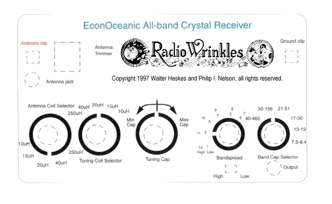
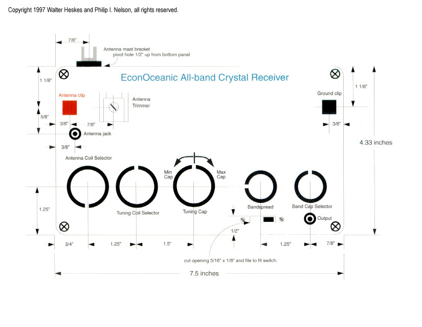
The Component Layout Diagram and
Cabinet Decal show you where
to drill holes in the cabinet front panel for the components.
Carefully trim the decal to fit the cabinet, then punch or cut
holes in the decal where indicated. Glue on the decal. Don't
put any glue under the places where you'll be drilling holes.
Using a scribe or sharp knife, and guided by the scribe marks
on the decal, make a little guide hole in the exact center of
each place to drill. Using a sharp knife, carefully trim away
the paper from each hole, so the drill won't tear the paper.
Regarding the decal, not all printers are created equal, so
make sure it's printed at the right size before gluing it on.
At the correct size, the decal measures 7.5 inches wide (horizontally)
at the trim lines. If you can't get it to print correctly, you can
try loading the image into a graphics program such as Photoshop or
Paintshop Pro and resizing it for a new printout. The component
layout diagram gives exact measurements for the holes, in any case.
Before you drill any holes, check clearances by placing the actual
knobs in place atop the diagram. Now drill the holes.
Drilling plastic is fast and easy. Wear protective eyegear
to guard against flying fragments of plastic.
If you'd like to protect the paper decal against dirt and wear, spray
on a thin coat of clear lacquer or poly finish, then set it aside to dry.
A more permanent solution would be to have it laminated beforehand at
a local copy shop.
Finally, mount the components in the positions shown in the component
layout diagram. Pop the front panel into the case and admire your work.
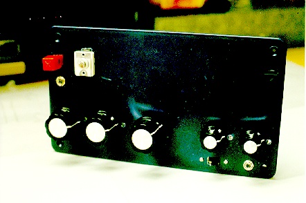
From the outside, this
project looks almost finished—all that's left is to build the
radio that goes inside!
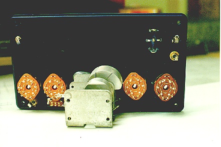
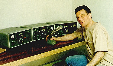
Below are front and rear views of the author's prototype,
after mounting the controls on the front panel. (This prototype
did not have a decal.)
Building the Switchable Coils
Switchable coils are a unique feature of the EconOceanic.
With many old shortwave radios, changing bands required
you to unplug one coil and plug in another.
With the EconOceanic, you simply turn switches
to change coils in or out. That's more convenient, and it
reduces wear and tear on the coils.
Making a Rigid Coil Form
In the EconOceanic, all of the BC and SW coils will be wound
on a single core.
The first step is to get something to wind your coils on.
A standard roll of paper towels comes
on a 1 5/8-inch diameter cardboard tube, which is just
right.
Although you can wind the
coils on a single tube, it's a good idea to reinforce the tube
with a second stiffening layer, to help resist the tension
of the wire as you wind the coils. To create the reinforcement, get
an extra cardboard tube, slice it down its length,
and remove a 3/8-inch wide strip along the cut, thus
reducing its diameter. (Remember that this inner tube has to fit
inside another tube of the same original diameter.) Apply a thin
layer of Elmer's Glueall to the entire outer surface of the inner
tube and insert it through the outer tube. Let it expand and gently
press the tubes together to spread the glue. Hold them together for a
couple of minutes, then set them aside
for the glue to dry. Now you have a single, thick core.
Marking Eight Sections on the Coil Form
This design requires precise winding, which will be easier if you
take a moment to mark your core with lines along its length to
indicate its halves, quadrants, and eighth-sections.
(In other words, draw eight equally-spaced straight lines, each
one going the entire length of the tube.)
When you need to wind a coil of 22 3/4 turns, you'll
know exactly where to stop during the 23rd turn.
The more accurate your coils, the better they'll work.
A coil with the wrong number of turns provides the
wrong inductance and will not tune the desired range
of frequencies.
Winding Your Coils
It's time to start winding, a task that requires care.
Here's a little trick that simplifies the process.
As you wind each coil, it helps to apply a thin layer of Elmer's Glueall
to hold the most recently wound section together. Otherwise, the wires tend to
spring apart (if that happens, you have to rewind the coil from scratch.)
Wind about 10 turns, hold them tightly in place with your thumb, apply
a pea-sized glob of glue to the wound section, and spread it with the
middle finger of your other hand.
Work the glue between the coils to encapsulate them.
The thin layer dries in a few seconds and you can quickly continue winding.
It's a technique you can develop pretty quickly. By the time you've wound
all 101.5 turns of the big broadcast (BC) band coil, you'll feel like an expert!
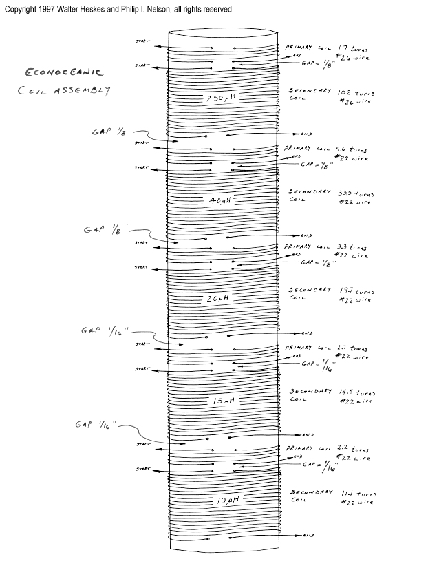
Wind one coil at a time, following the Coil Winding Diagram.
Use a full spool of wire when you start winding the big BC coil.
It can be heartbreaking to run out of wire just before you reach the end.
Leave 10 inches of extra wire at each end of each coil. It is better to
have extra length now which can be trimmed away later. These ends are the leads that
you'll connect to the other components.
Mark each lead wires using a little flag of masking tape (for instance,
"250 uH Antenna" and "250 uH Ground"). The markers will simplify hookup later on.
The chart below lists the number of turns and size of wire to use for each coil.
This radio tunes five bands. Each band requires a pair of windings: a small
primary and a larger secondary.
Coil
Section |
Number
of
Turns |
Wire
gauge |
| 250uH primary |
17 |
26 |
| 250uH secondary |
102 |
26 |
| 40uH primary |
5.6 |
22 |
| 40uH secondary |
33.5 |
22 |
| 20 uH primary |
3.3 |
22 |
| 20 uH secondary |
19.7 |
22 |
| 15 uH primary |
2.3 |
22 |
| 15 uH secondary |
14.5 |
22 |
| 10 uH primary |
2.2 |
22 |
| 10 uH secondary |
11.1 |
22 |
Each winding must be separated by a small gap from the next.
Leave a 1/8-inch gap between windings for the 250uH, 40 uH, and
20 uH coils. Leave a 1/16-inch gap between the 15 uH and 10 uH coils.
Winding can be tedious, but it doesn't pay to rush. If you do this
part correctly, you'll have a good-performing radio that performs
virtually maintenance-free for many years.
When all the winding is done, check your work to make sure
that everything is tight and secure. If necessary, apply more glue where needed.
You can also apply a thin coat of clear varnish, if desired, for a more
finished appearance.
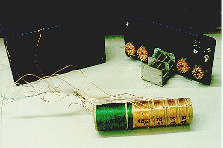
This photo shows the author's prototype coil, ready for mounting.
Mounting the Coils
Mount the coil assembly to the inside surface of the front panel.
Check for adequate clearance when the tuning capacitor is fully open.
Leave about
1/8-inch minimum clearance between the open rotor and the coil assembly.
The rotor and coil must not touch. Mark the center of the coil form and
mount self-sticking rubber feet to the centerline of the coil form. The feet
serve as standoffs from the front panel, providing some clearance
under the coil through which you can pass wires.
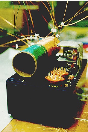
This photo shows the author's prototype coil mounted inside the front panel,
which was placed upside down on the cabinet for the photo. Note the little
plastic ties used to keep related leads together.
Wiring the chassis
Before you start hooking up components,
take a few moments to study the schematic diagrams carefully.
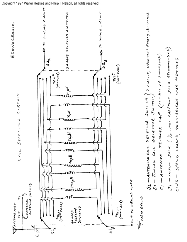
The ones you'll be using are the Coil Selector Circuit and Tuner/Detector Circuit.
Connecting Wires for Antenna and Ground
Let's start by attaching lead wires to the antenna and ground connections.
These are shown in the Coil Selector Circuit.
Connect wires to both antenna input jacks, the antenna trimmer, and the ground input jack. Check your connections for correctness and solder them.
Connecting Coils to the Coil Selector Switch
Identify the pinouts of the rotary switches. Use an ohmmeter to check continuity across the switch circuits and note the position of the switch pointer as each circuit is made. When you are certain you understand how the switch circuits are opened and closed, start wiring the antenna coils to the antenna coil selector switch.
Measure the length of wire needed to span the distance from the coil to the lug at the rotary selector switch. Straight runs are fine. Minimize the
number of right angle bends, since those can reduce circuit sensitivity.
Trim the coil takeoff leads to approximately 10 inches.
Using a razor blade or fine sandpaper, carefully scrape the enamel coating off each lead wire before you thread it through a lug on the rotary switch. Be
careful not to break the fragile lead as you bend it around the lug.
Checking Coil Connections
Do not solder any connections until you have checked for proper continuity through each switch circuit and its coil. Refer to
the Coil Selector Circuit as
needed while checking your work.
Wiring Tuning Coils
After all the antenna coils are wired to the rotary switch, you can
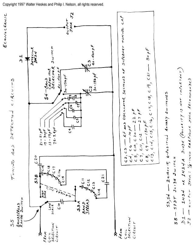
begin wiring the tuning coil circuits, referring to the
Tuner/Detector Circuit diagram.
Again, check for continuity through each switch circuit
and its coil. Do not solder until all leads have been properly wired.
Next, connect the leads of the tuning coil to the tuning capacitor.
Connecting Capacitors
Connect the ceramic capacitors to the bandspread rotary switch. This is tedious
work because the capacitor leads are short and the spacing between adjacent
rotary switch lugs is small. Work slowly and carefully.
Connect the leads to the bandspread hi-lo selector switch.
Since the DPDT
switch has two circuits and only one circuit is needed, you can wire across both
circuits if that makes wiring a bit easier for you. Or, use a larger SPDT
switch.
Making Final Connections
Connect the 1N34 diode to the phone jack and to the band capacitor
selector switch. Polarity is not important.
Connect the capacitors and leads to the tuning capacitor selector switch.
Connect the leads to the output jack.
Final Check and Soldering
You're almost done! Before soldering any connections, follow the schematic diagrams and
recheck every connection for continuity. Correct any wiring errors that you find.
When you're sure that everything's hooked up correctly, solder each lead.
Mounting the Antenna
The EconOceanic can use many different kinds of antennas. You'll
get the best reception from a long outdoor antenna, of course.
In many areas, however, you can get respectable performance from the
6-foot telescoping antenna listed in the Parts List.
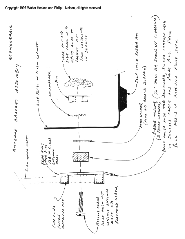
To mount the telescoping antenna, modify one of the fuse holder clips
as shown in the Antenna Bracket Assembly diagram.
The clip forms a swiveling support for the antenna mast. To fasten the antenna mast assembly to the cabinet, you'll also need a small screw, rubber washer, metal washer, lockwasher, and nut.
Using Your Radio
Your EconOceanic radio is completely assembled. Now for the exciting part—using it!
This description may sound harder at first than it really is in practice. We'll go
through the process simply because it's a little more involved than using
Step 1. Connect antenna and ground. Connect your antenna and ground wires to the appropriate terminals on the front panel. If you are using the
telescoping antenna, it is already connected, of course.
Step 2. Connect listening device. Plug in your 2000-ohm headphones or, better yet, use Radio Shack's amplified speaker so everyone can listen at the same time. The amplified speaker is a transistorized amplifier connected to an internal speaker. It also has a 1/8-inch phone jack, allowing you to listen without disturbing others.
The author connected the output of the amplified speaker to a good quality high fidelity speaker. Later, the author added a second amplified speaker to the radio. The second stage amplifies the weakest signals to audible levels and easily fills the room with sound. This diagram explains the connections:
| Connect this
. . . |
To this |
| EconOceanic output jack |
Input jack of first amplified
speaker |
| Output jack of first amplified
speaker |
Input jack of second amplified
speaker |
| Output jack of second amplified
speaker |
Hi-fi speaker |
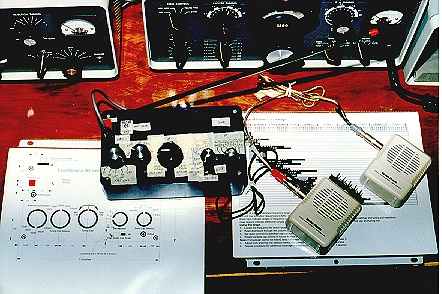
This photo shows the author's prototype, with temporary labels on the panel, connected to two amplified speakers in series.
Step 3. Choose a Station. Depending upon the time of day and your location in the world, you can tune across the SW bands and listen in on broadcast activity. Some of the
SW bands are more active in the evening hours, while others operate during the day.
Consult a schedule of shortwave broadcasts and note the time of day and frequency at which a desired broadcast will occur.
Schedules are published in SW hobbyist magazines available at better newsstands. You can also find loads of schedule information on the Web,
such as this resource page at SWLing.com.
Another good resource is the book World Radio TV Handbook.
Step 4. Look up tuner settings.
Use the Bar Graph of Continuous Coverage to find the correct capacitor and coil settings to tune in the desired frequency. Print this chart using your printer's landscape mode so that it will fit on a single 8.5x11-inch sheet.
As you become more familiar with the principles of resonance, you will find that you can tune the receiver to the desired frequency by thinking about the resonance formula and selecting coils and capacitors according to the following logic:
| Low-frequency
Broadcasts |
High-frequency
Broadcasts |
| Most capacitance |
Least capacitance |
| Longest coil |
Shortest coil |
For example, to tune the AM broadcast band, you would select your longest coil (250uH) and your biggest capacitor setting (460 pF). Similarly, to tune the highest shortwave frequencies, you would select your shortest coil (10uH) and your smallest capacitor setting (7 - 9 pF).
It's possible to receive the same broadcast signal with different combinations of coils and capacitors. The best combination is the one at which the incoming signal is loudest. Experiment and learn the best settings.
You can also combine dissimilar primary and secondary coils to receive radio signals. That is, you can set the antenna coil to 250uH and the tuning coil to 20uH and you will receive SW signals. This occurs because of the inductive coupling effects of the multiple coils on the same coil form.
Remember that the tuning coil alone determines the frequency at which radio signals will be received. The tuning coil resonates with the tuning capacitor. The antenna coil merely feeds the incoming radio waves to the tuning coil.
Enjoy this advantage of mounting several adjacent coils on the same core.
Step 5. Turn the antenna coil selector switch to a desired primary coil.
Step 6. Rotate the tuning coil selector switch to the associated secondary coil.
Step 7. Turn the band capacitor selector switch to a desired setting. Now the band is selected.
Step 8. Rotate the tuning capacitor to select a broadcast signal within the selected band.
Step 9. Starting at the lowest setting of the "low" bandspread scale, adjust the bandspread switch for maximum broadcast signal loudness.
Step 10. If you are using the amplified speaker, adjust the volume to a comfortable setting. If you are using a pair of unamplified, 2000-ohm headphones, there
is no loudness control.
Step 11. Log your settings. On a sheet of paper, write the time of day, the settings of your selector switches, and a description identifying the source of the broadast signal. For example, you might write:
9 P.M. EST, 20uH A coil, 20uH T coil, 13-19 pF, Radio Havana (Cuba) 8.9 MHz.
Logging your reception reports will help you locate your favorite radio broadcasts.
Documenting your work also adds a hint of substance and credibility to your DX sessions.
Above all, have fun!
Theory of Operation
This block diagram shows each stage of the EconOceanic crystal shortwave receiver. Click on each component to read more about it.
     Aerial
        |
        |
  Antenna coil-->Tuning coil-->Tuning capacitor-->Detector-->Output
        |
        |
  Earth ground
Aerial
The aerial's job is to capture electromagnetic waves from all sources and directions and funnel those charges into the antenna coil. The loudness of received signals is directly proportional to the height and length of the aerial. Mount the aerial as high as possible, preferably outdoors. A single wire 100 feet long makes an ideal aerial. The EconOceanic design provides for two antenna connections: one 1/8-inch phone jack and a spring-loaded clip (originally intended for fastening hi-fi speaker cables).
If your antenna is mounted outdoors, you should disconnect it whenever there is any chance of lightning in your vicinity.
Antenna coil
The antenna coil is the primary winding of the pair of coils that make up the antenna-tuning transformer. It is a fraction (1/6) of the number of turns that make up the tuning coil. The secondary coil multiplies the electrical field created by the antenna coil.
Earth ground
The earth ground connection effectively extends the antenna into the
earth, which contains electrical signals. Keep the ground wire as short and
straight as possible. There may be some sensitivity loss if the excess
ground wire is coiled into a loop. Use either a metal cold water pipe that is
buried at least several feet in the ground or an electrical conduit that is
similarly buried or grounded. You can usually make a satisfactory ground
connection using the screw that fastens the cover plate to an electrical
outlet box.
Tuning coil
The tuning coil is the inductor which, in series with the tuning capacitor, determines the resonant frequency of the receiver according to the formula: frequency = 1/[2*pi*sqroot(L*C)]. Wind your coil carefully and space it close
to the antenna coil (about 1/8" apart) to tune the specified frequencies.
The amount of coupling is directly proportional to the distance between the
windings. If you slide the windings far apart, there is little coupling and a narrow
resonance peak (e.g., 100 KHz). If you move the windings closer, there is more coupling and a broader resonance peak (e.g., 200 KHz). A broader resonance peak
will mean less selective tuning; that is, several stations will be heard
simultaneously at one tuner setting. Experiment, if you wish, with spacing
your coils. For example, try 1/4-inch between the primary and secondary
windings and test your design for selectivity. Have fun as you learn.
Tuning capacitor
The tuning capacitor is the variable component in the "tank" circuit
which comprises the coil and the cap. By varying the capacitance, you can
change the resonant frequency of the receiver within the limits of the
coil inductance and the total capacitance available in the variable capacitor.
Detector (diode)
In this radio, a diode serves as the detector, separating the fluctuating direct current (containing the voices and music of the broadcast) from the amplitude-modulated, radio-frequency, alternating-current carrier wave that was transmitted from the radio station antenna. The direct current generated by the detector will drive the output device.
Output (headphones or amplified speaker)
The output device changes the electrical energy in the detector circuit
into mechanical energy that moves air against our ears to create sound.
For satisfactory sound output, this needs to have an input sensitivity of a
few millivolts and an input impedance of a few thousand ohms, such as a pair of 2000-ohm
headphones or Radio Shack's amplified speaker (part no. 277-1008). Don't
try to use a permanent-magnet speaker, such as one scrounged
from an old radio. Permanent-magnet speakers require more DC energy
than a crystal set can generate.
If you completed this project and enjoy using your EconOceanic, please drop us a line and share your experiences. Walter's email address is
walterh@interworld.com.
This radio construction project, including all descriptions, diagrams, photos, and the underlying electronic design, is published here for the noncommercial use of radio hobbyists. You may print and reproduce these project instructions for your personal use. Commercial use of this material is strictly forbidden.
|