U.S. Army Model AN/GRR-5 Shortwave Receiver (1959)


Affectionately known as the "Angry 5," the AN/GRR-5 compact mobile shortwave
receiver was used in the United States military during the 1950s and 1960s. Here is
one man's view of the radio's mission:
The GRR-5 was contracted as a gas warning receiver, in other words it was
supposed to be mounted in vehicles and used to sound the alarm of a gas
attack. Later expanded to include nuclear and biological attack. It was
not a communications receiver. The circuit is something like a Zenith
Trans-Oceanic of the era. Since it was a solution to a nonexistent problem,
most of them were not deployed and were sold off as surplus in the 1978-85 era.
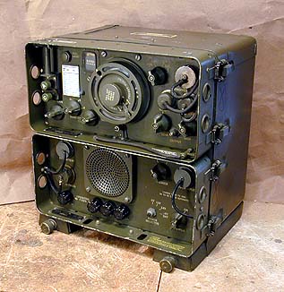
The complete radio consists of two chassis: the model
R-174/URR receiver and the model PP-308/URR power supply. The two-compartment
cabinet has the model number CY-615/URR. Here is the complete
radio as normally seen, with the two chassis inside the cabinet.
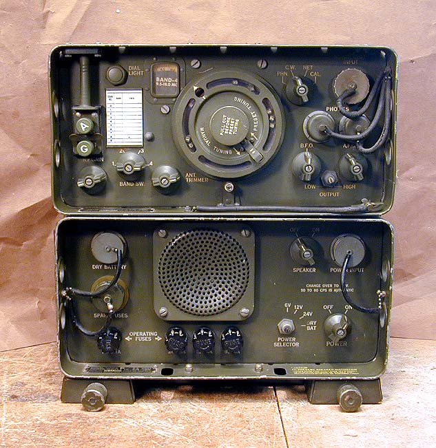
The next photo shows the radio's controls. The receiver chassis sits above
the power supply chassis, which also contains the speaker. In the center of the
receiver is the large circular tuning knob, which can be moved to preset frequencies
by pulling out the smaller center knob.
This radio covers 1.5 Mhz - 18 Mhz in four bands. (Thus, it does not cover
the standard broadcast band.) The smallish tuning dial is located above and
left of the tuning knob. On the left are large connectors
for antenna and ground, the RF gain knob, and the four-position bandswitch. The
antenna trimmer knob lies left and below the tuning knobs.
At upper right is a Monitoring Input connector with removable cap. To its
left is a four-position mode switch (PHN, CW, NET, CAL). Just below are two
Phones connectors, also with removable caps. The BFO and AF Gain knobs are
located at lower right, and nestled between them is a two-position output
switch (LO/HI).
In the center of the lower power chassis is the rugged little speaker
grille. To its left are two jacks with removable caps. The upper one is for
connecting a dry battery cable; the lower one is a container for spare fuses.
The fuse caps themselves are located in a row along the bottom.
At upper right is the Power Input jack for connecting an AC or non-battery
DC power source. To its left is the speaker on/off switch, and below it is the
main power switch. Left of that is the four-position Power Selector, with
positions for 6V, 12V, 24V, and Dry Battery. A legend on the front panel notes
that changeover to AC power is automatic.
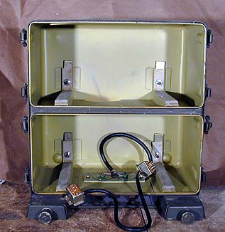
The next photo shows the cabinet with both chassis removed. A thick
rubber-coated cable connects both chassis when they are installed.
Heavy spring-loaded clips on each side hold the chassis securely in each
cabinet. Be careful to keep your fingertips out of the way when releasing these
clips. They can bruise your finger as hard as a powerful rattrap.
First Impressions
I bought this receiver at an auction of radio goods in Kennewick,
Washington, in October, 2001. My winning bid was a whopping $26—a good price, in my view.
I wasn't familiar with this receiver, or any military receivers, for that
matter. The frequencies on the tuning dial indicated that it was a
general-coverage set (within a somewhat limited range), so I figured it was worth a try.
I fashioned a temporary power cord, connected an antenna, then slowly powered up the set using a
variac. I was pleased to discover that it worked.
Not wishing to press my luck with this unrestored set, I powered it down
until I could check out its old capacitors and other power-supply components.
The 129-page military manual is very detailed. You can download the
document (a 27-megabyte PDF file) from this link:
AN/GRR-5 Military Service Manual.
Electronics
The AN/GRR-5 has been described as a "Zenith TransOceanic on steroids,"
which is not too far from the truth. Both radios are high-quality multi-band
portables, which use low-voltage miniature tubes. Here is the tube lineup for
the Angry 5.
| Tube |
Type |
Function |
| V1 |
1L4 |
1st RF amplifier |
| V2 |
1L4 |
2nd RF amplifier |
| V3 |
1R5 |
Converter |
| V4 |
1L4 |
1st IF amplifier |
| V5 |
1R5 |
2nd IF amplifier/Cal.osc. |
| V6 |
1U5 |
Detector/AVC/AF amplifier |
| V7 |
1R5 |
Low AF amplifier/BFO |
| V8 |
3V4 |
High AF amplfier |
With two stages of amplification in the RF and IF stages, you would expect
good sensitivity from this receiver. The audio section can't compete with
the push-pull audio offered by a TransOceanic 8G005, but given this radio's
mission, luscious sound quality was a low priority.
The AN/GRR-5 also includes "boatanchor" features which are
lacking in the consumer-oriented TransOceanic. These include BFO, an antenna
trimmer, and calibration, as well as a clever system for automatic tuning to a
number of preset frequencies.
Designed for service in the field, the AN/GRR-5 is built to rugged
standards. The next photo gives a view of the top of the receiver chassis.
From this view, you can see part of the husky gear-driven tuning mechanism
near the chassis front. Note the golden appearance of some components. This is
weatherproofing varnish, applied to prevent fungus growth and moisture damage
in humid climates.
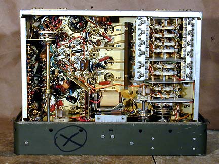
The next photo shows the receiver chassis underside. Notice the ceramic
forms in the bandswitch, an indicator of the high quality. With an original
(1951) cost of $835.78, this radio was definitely not cheap!
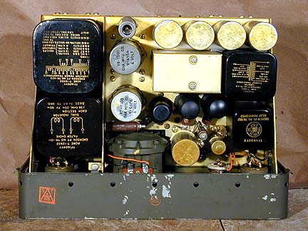
Packed with transformers and other heavy components, the power supply
chassis accounts for a good chunk of the AN/GRR-5's total weight. It employs
four tubes and a vibrator for the filament supply.
| Tube |
Type |
Function |
| V101 |
6AG7 |
B+ voltage regulator |
| V102 |
CK1007 |
High voltage rectifier |
| V103 |
0B2 |
Reference voltage regulator |
| V104 |
6AG7 |
Filament voltage regulator |
Below is a photo of the power supply chassis top.
The husky speaker frame is visible near bottom center of that photo. A note
on the power supply advises you to loosen the spare fuse cap to prevent
distortion from the speaker. The AN/GRR-5 is well sealed against the elements.
Some folks claim it will actually float if thrown into a lake!
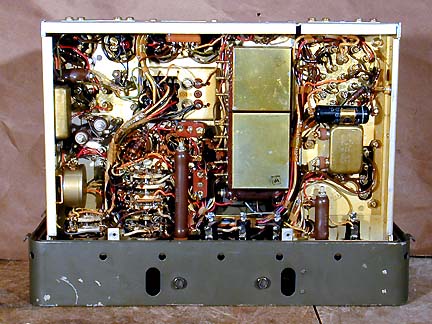
The next photo shows the underside of the power chassis. You can see a fat
"Black Beauty" capacitor near right center. It's the only one that I
noticed on first inspection. You can be sure that I'll replace that unreliable
capacitor before using the radio any further. (See Replacing Capacitors in Old Radios.)
This radio's power supply is much more complex than what you'll find in a
consumer-grade radio. Firstly, the radio accepts four different power inputs:
110-volt AC, or DC in 6, 12, or 24 volts. Secondly, the supply offers a level
of regulation (and hence, operating stability) usually found only in high-end
communication receivers.
If you are looking for AN/GRR-5 accessories or parts, such as a whip antenna or
power supply connector, try contacting
Fair Radio, a military surplus supplier.
Final Thoughts
This radio is currently waiting its turn for restoration. Although it plays
pretty well, its copper oxide rectifier is known to be unreliable, and I will
at least check, if not replace, its electrolytic capacitors as well any paper
or plastic capacitors.
I haven't quite figured out where to keep the radio once it has been restored.
It wouldn't quite go with the decor in most parts of our house. In the
meantime, however, it adds a little macho to the radio shelves in
my workshop!
Here are some contributions from fellow AN/GRR-5 owners who visited
this page.
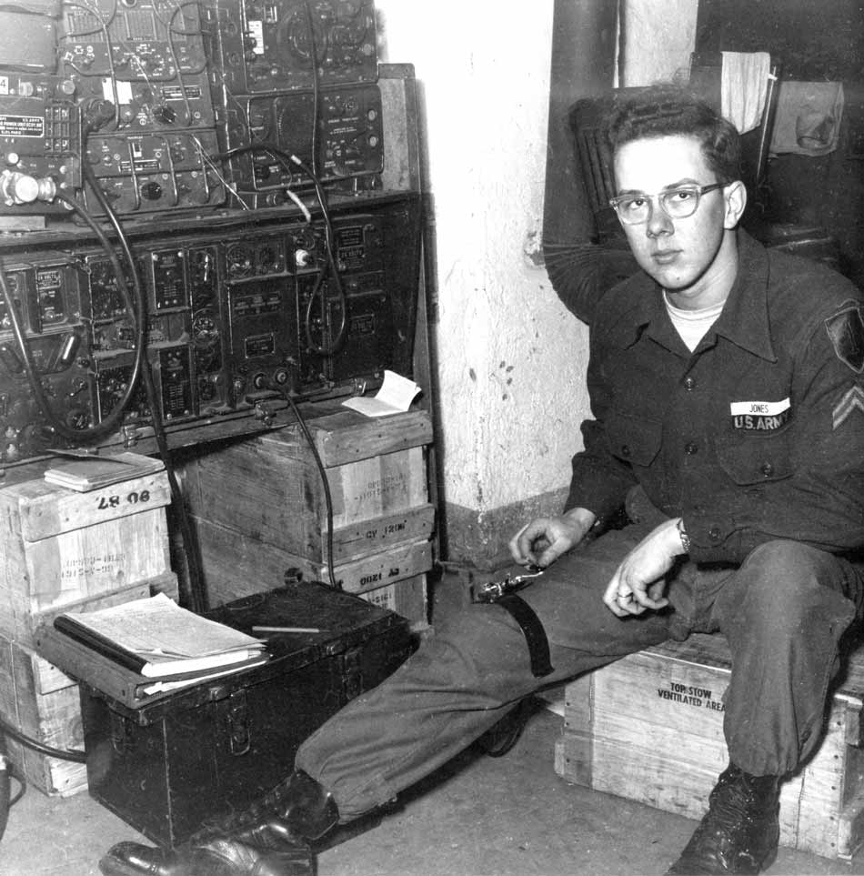
First, here's a 1954 photo of Jim Jones on duty in his Army unit's
communication station in Germany. The AN/GRR-5 is at upper right
in that stack of equipment.
Here are Jim's comments on how the AN/GRR-5 was used in service.
Great receiver. We used it, in addition to its regular duties,
as a receiver for our ham station with a homebrew transceiver.

Notice the AN/GRC-9 next to the 5. We used these in the First
Infantry Division Artillery net. This was a CW net and I spent
eight hours a day, seven days a week operating the station.
When I got out of the army in 1955, I did not want to hear
another dit or da again, but I relented and got my ticket a
few years later.

The division artillery net was a 24 hour communication net
that was our main means of contact with division headquarters.
Every half hour, the headquarters station would call the net
to make sure everything was OK. It was all in Morse code;
divarty would send "QRU QRU?" which meant "I have nothing for
you, do you have anything for me" and we would reply "QRU".

After each communication we then called the Officer of the
Day and informed him "Communication OK, Sir." This was done
whether we were on post or in the field.

Jim Jones
NG9E
Here are some comments from Berj Ensanian:
My opinion on this radio: I'd trade a hundred R-390As
for one good AN/GRR-5. I used to know a lot about 390s
(had so many of them back in the old days I once built
one from just spare parts starting with the bare sheet
metal panel), so I'm serious. Here's why: the AN/GRR-5
is an excellent HF receiver designed to operate anywhere
from the desert to the arctic, from just about any
easily obtained power (and not much at that), with any
old wire that can be quickly clipped on, dials glow in
the dark, floats if the cork is still good, is its own
great speaker cabinet, very easily repaired/maintained/
emergency-modified, EMP-proof, can serve as a chair, etc.
So, if/when the planet's affairs crash, and all the
390s cease being shack furnaces, the sweet little
AN/GRR-5s will be hard-to-beat survival receivers.
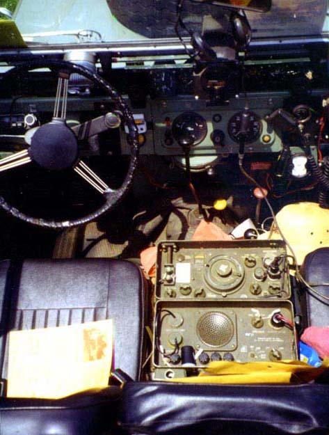
Here's a photo of Y.A. Feder's AN/GRR-5 installed in his 1963 3/4-ton Land Rover.
Now, that's one heck of a car radio!
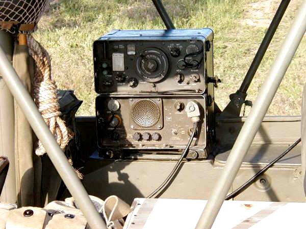
Finally, here is Chris Jones' AN/GRR-5 mounted in the back
of his WWII Willys Jeep.
You can see more photos of Chris's jeep and his "Angry 5"
at his photo pages 1 and 2.
If anyone else has comments or photos of an AN/GRR-5 in
action, send me an email. Maybe your
Angry 5 can appear here, too!
|