Radio Lamp Company of America Radio (1939)


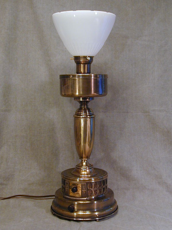
This handsome brass table lamp has a radio in its base.
It was manufactured in the late 1930s by the Radio Lamp Company
of America.
Description
Here is the restored radio lamp:
The radio is divided in two parts, with the chassis in the base and the
speaker in the bowl-shaped enclosure under the glass light diffuser.
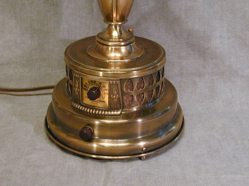
The next photo shows the radio's simple controls: one knob in front of the
translucent tuner dial and a second knob below it for power and volume.
Peeking from the rear of the base is a rotary switch that
independently controls the light.
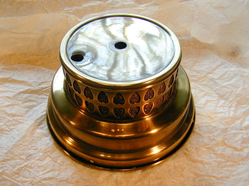
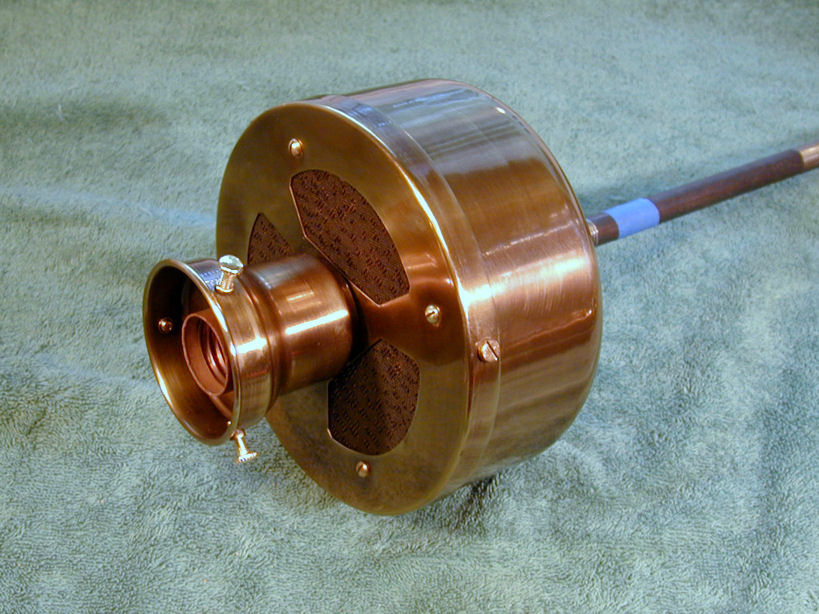
A decorative cast metal bezel surrounds the dial scale. The double row of heart-shaped
openings provides ventilation for the radio chassis, with grille cloth
to keep out the dust.
The Radio Lamp Company of America must have been a pretty small outfit. It is not
listed in the Riders service manual index and no other radios are attributed
to this company in my collector books. Send me an email
if you have found any ads, dealer brochures, owner's
manual, or other literature from Radio Lamp Company of America.
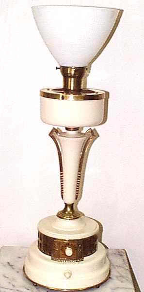
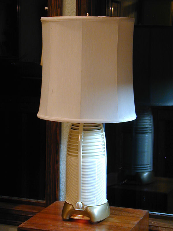
These radio lamps were produced in several styles, all with the same base. Different models had various styles and colors.
My radio is a Model 100 and it originally sold for $35. In a second style, Model 95, the center section has a different shape and
portions of the case are painted an ivory color:
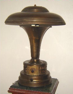
A third style, Model 500, was described as the "Executive Office Lamp." It is shorter,
with a tapered center and a metal umbrella shade.
There was even a model 3000 with center parts made of light onyx.
Except for the Model 500 with metal shade, all of these radio lamps were originally sold with a fabric shade that sat on top
of the glass bowl. The fabric shades were pretty generic looking. I haven't placed one on
my radio because I like being able to see the entire metal case.
Like most novelty radios, this one has a basic five-tube
chassis. The tube complement is conventional for a late 1930s set,
with types 12A8GT, 12K7GT, 12A7GT (or 12Q7GT), 35L6GT, and 45Z5GT.
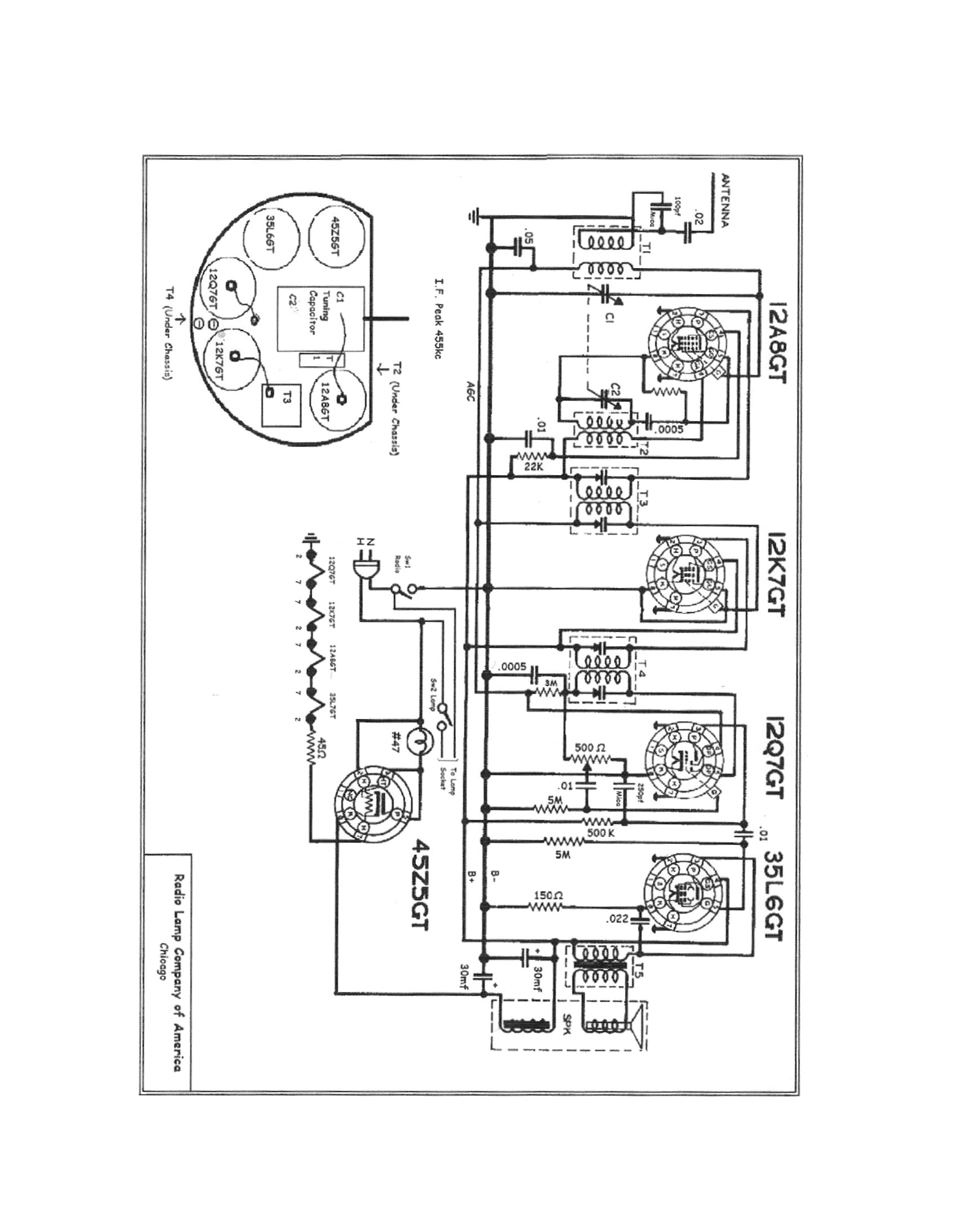
Years after I restored the electronics on mine, a fellow collector sent me
a schematic diagram for this radio. (Thanks, Joe!) To download it, right-click on the following
icon and choose Save Target As:

Since I was working without a schematic at the time, I recapped my set by reading
the values printed on the old capacitors and installing new ones of equivalent value.
(You can read more about capacitor replacement in my recapping
article.) If you find that your radio doesn't match this schematic exactly, I would
go with whatever capacitor values you find in your radio.
The radio lamp uses a long wire antenna. Its all-metal case precludes an internal
loop antenna, and this design has no spare room inside, anyway.
With simple electronics and a small speaker, don't expect high fidelity or powerful
long-distance reception from this set. High performance is not why people
bought these sets. They are attractive table lamps that happen
to include a small radio.
Restoration
I purchased this radio lamp at a second-hand store in 2003. It was
complete and undamaged, but the brass finish was in poor shape.
I began by disassembling the radio, a complex job compared to the
average table set. To make sure I could put it back together
correctly, I photographed key details.
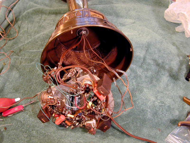
The radio lamp is disassembled from the bottom up. In the next photo, I
have removed the knobs and wooden bottom plate and slid the chassis partway out
of the base.

The radio chassis is insulated from the metal lamp body by wooden
blocks. In a series-string ("AC/DC") type chassis like this, the
chassis may be connected to one leg of the AC power line, so isolating
the chassis reduces the shock hazard. For added safety, you might
also want to operate the radio from an isolation transformer.
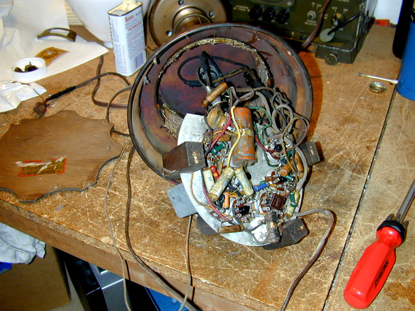
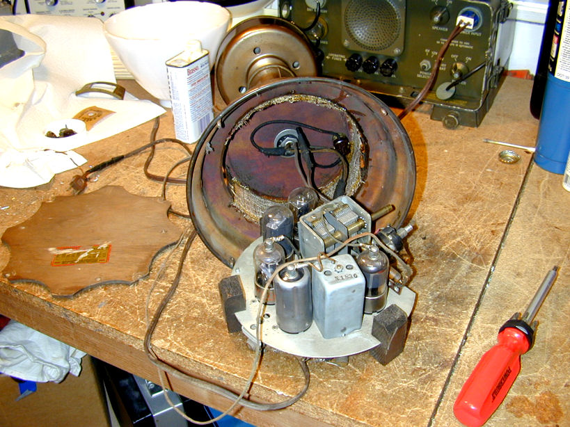
Next is a top view of the no-frills chassis. The layout is
very compact, generating lots of heat in a small space.

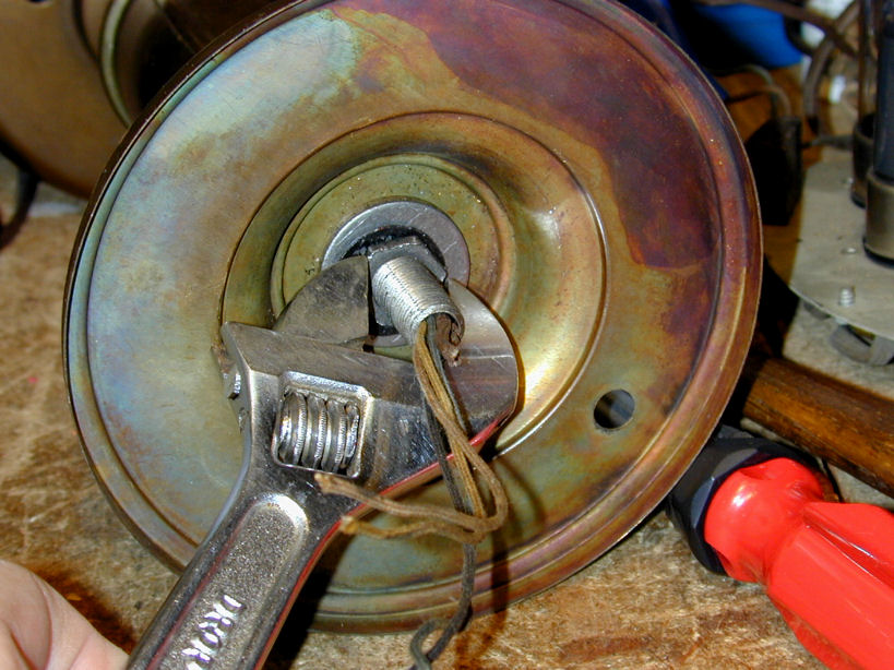
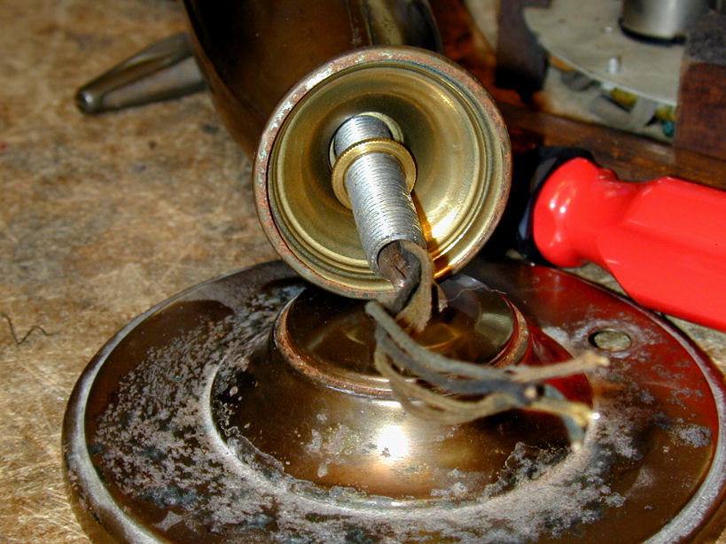
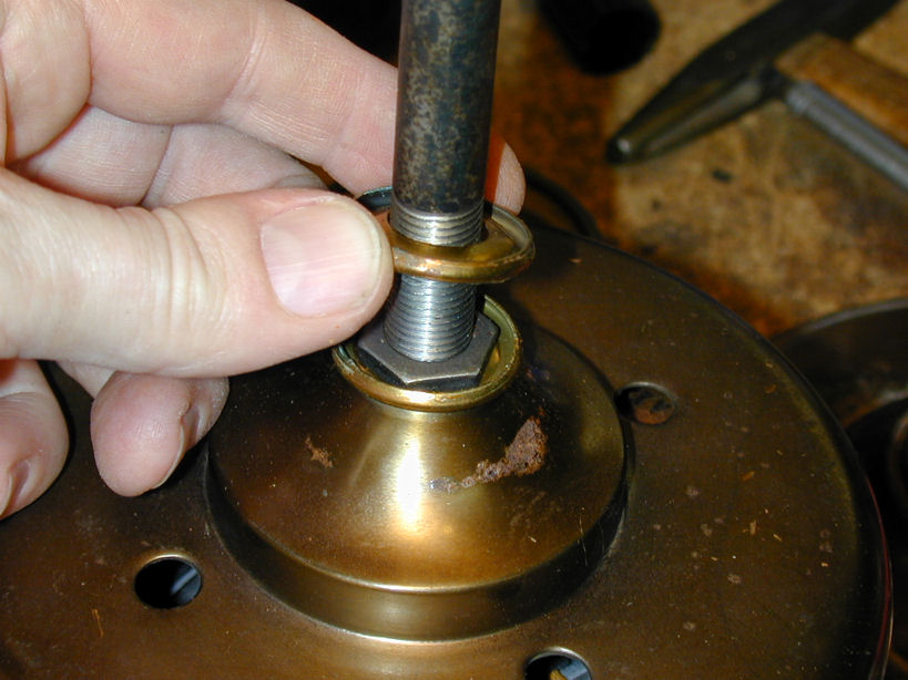
The base and other main parts are secured to a heavy
central pipe with stout nuts and lock washers. Wires
for the speaker and lamp socket are threaded up through the pipe.

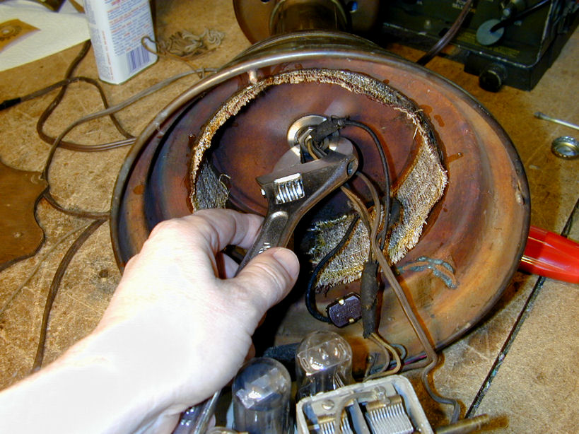
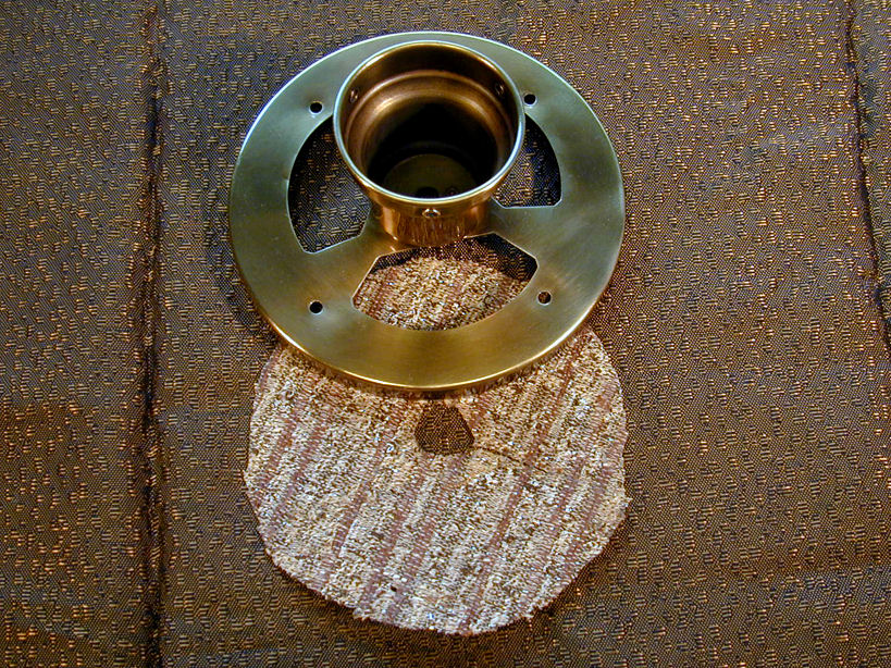
Working upward through the lamp body, we finally reach the speaker at the top.


The upward-facing speaker grille was stuck onto the speaker bowl
very tightly. After removing the perimeter screws, I had to
tap it free using a small hammer and a screwdriver blade,
taking care not to score the metal.
The speaker cone has been repaired in the past, but I won't freak
out over that until I hear the set play. This type of radio didn't produce
high-fidelity audio even when new, and often a little glue
won't change the way it sounds.
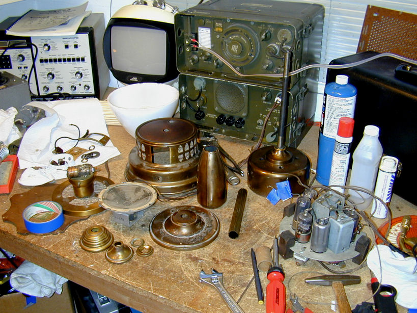
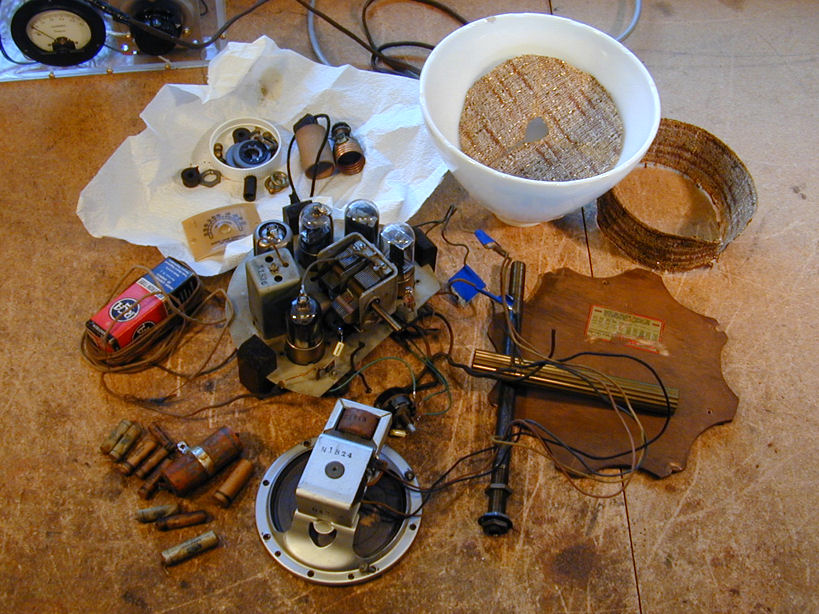
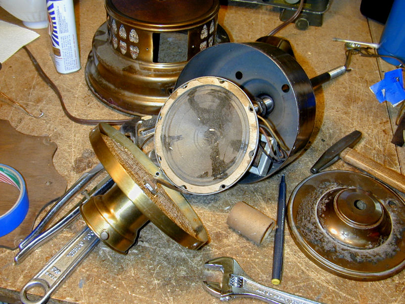
Whew! The radio lamp is disassembled at last. Notice the support
pipe still attached to the speaker bowl near the right.
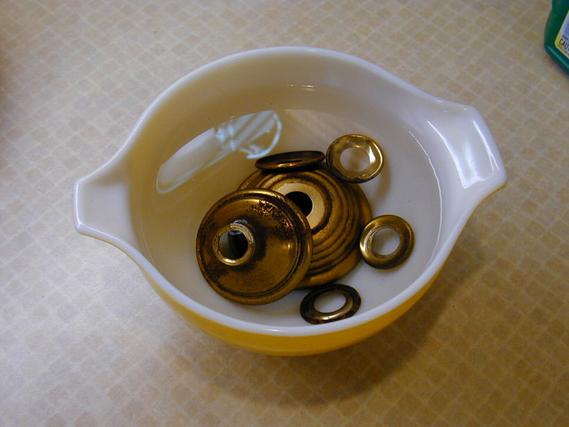
Some of the brass parts look pretty corroded, but I'll soak them in vinegar
for a while and then assess whether they can be
cleaned and polished. If too much brass is gone, they'll need replating.

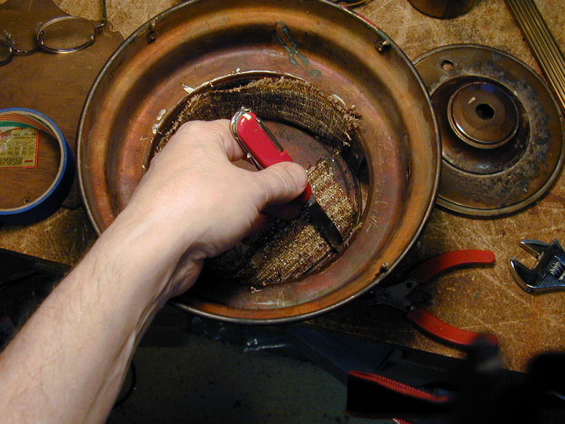
The crude fabric covering the speaker grille and vent openings must
be a slapdash replacement. It looks like heavy upholstery material, and
it's ugly to boot. Out it goes!

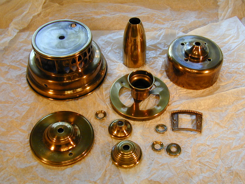
After treating the brass parts with vinegar, it was evident that some were
too corroded to polish back to normal appearance. I reloaded my wallet
and brought them to a local shop to be replated.
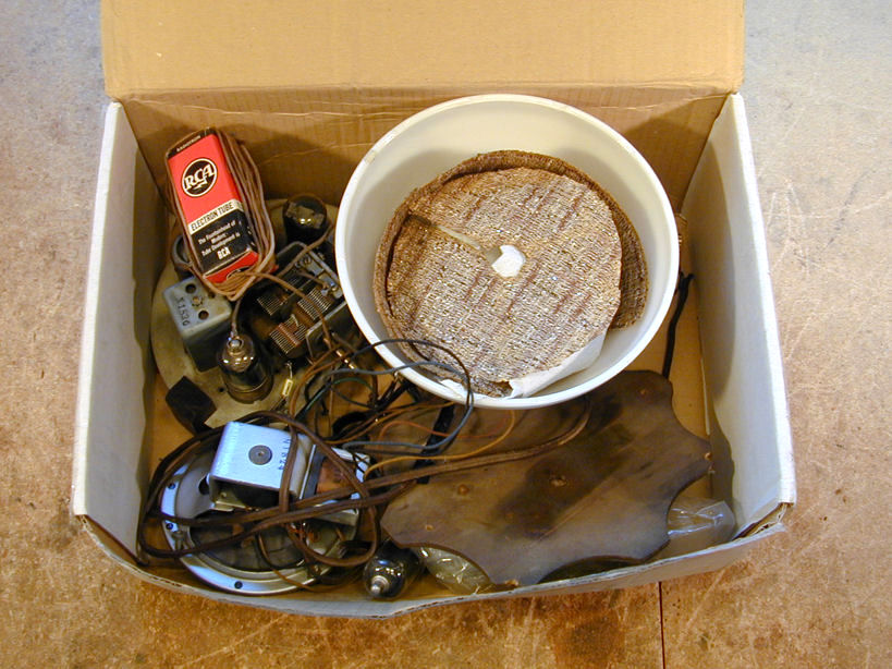
While the brass was out for replating, I restored the simple electronics
and put the chassis and other parts in a box.
Replating is not cheap. I paid more for replating the brass
parts than I had for the radio itself, but the results
were stunning and I did not regret the investment.
Fast Forward Nine Years
That's where the project stood for about nine years (!). The set
was restored and ready to reassemble, but I got distracted by other
projects and forgot about this one.
In the spring of 2012, I vowed to catch up on neglected projects.
After finishing my
Mitchell Lumitone,
this radio's turn came at last.
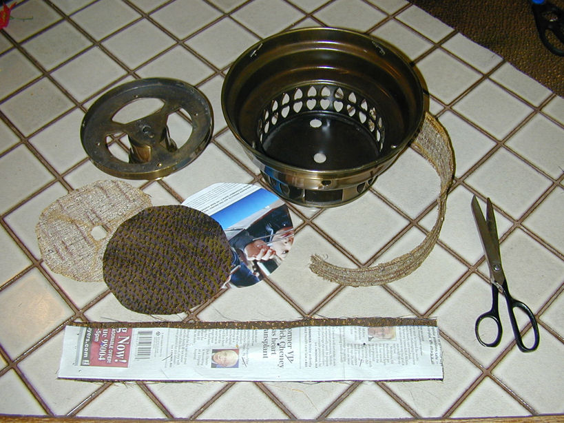
A brief treasure hunt in the back shelves uncovered the box
of replated parts and this second box containing everything else. Let's make a radio lamp!

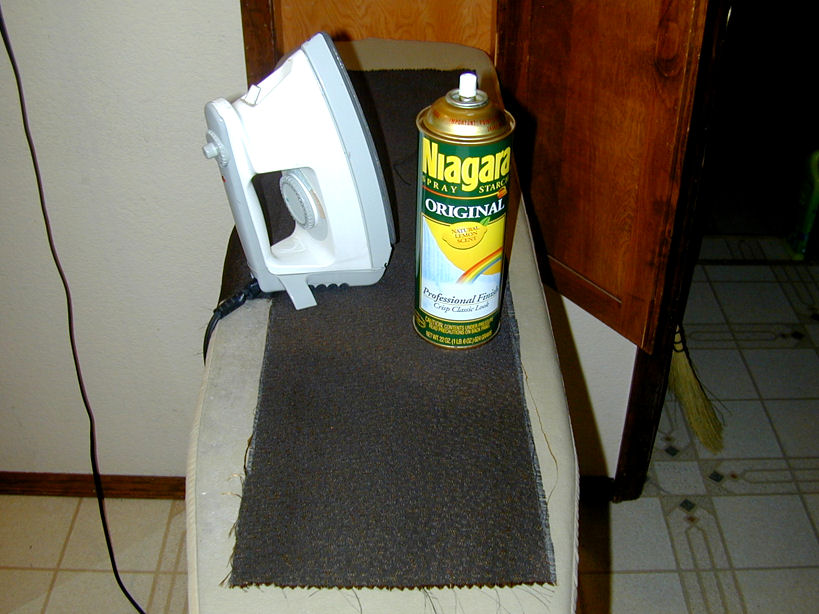
Replacing the Grille Cloth
Time to deal with the grille cloth. Picking a
compatible pattern from my stock of spares, I gave the new cloth a spritz of
starch and ironed it. I made paper patterns from the old pieces and pinned
them to the new fabric and then cut them out.


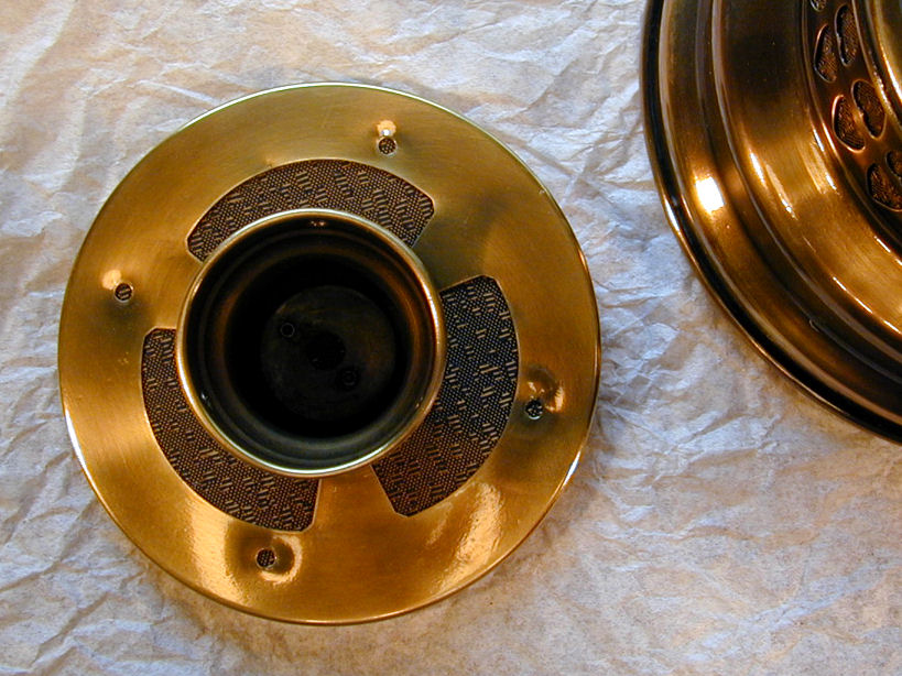
Gluing the strip of cloth inside the circular base was a little
tricky, but the installed cloth looks great. Its color compliments the
brass nicely and the pattern is unobtrusive.


Reassembly
Next, I did a test reassembly to make sure all that the parts fit correctly and that
I could put them back together with no leftover bits. Nine years is a long
time, photos or no photos.
Everything went smoothly except for replacing the grille piece on top of
the speaker bowl.
During disassembly, the grille had fit the bowl so tightly that I
had needed to carefully tap it off. Now, with a fresh brass plating covered by
thick coats of new lacquer, these parts were impossible to fit together!
Pounding the grille piece back on seemed like a bad idea, likely to
cause damage. The only alternative was to enlarge the joint between
these too-tight parts. Using a little sanding drum on a Dremel tool,
I carefully ground down the lip inside the top piece, and a matching
band around the rim of the bowl, until at last they could be slipped
together.

Prior to reattaching those pieces, I had drawn the wires for the lamp
socket and speaker down through the center pipe that holds everything together.
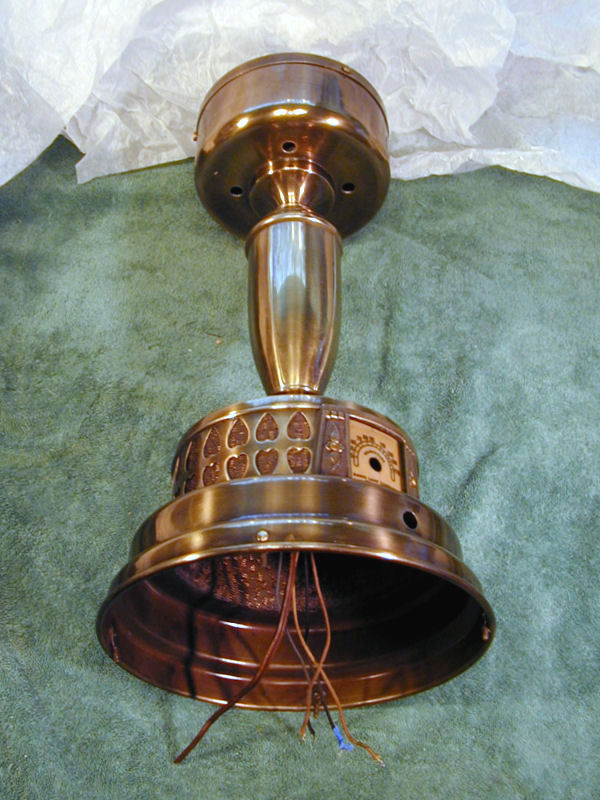
Reassembly proceeded from the top down. In the next photo, the entire
cabinet is reassembled and we're ready for rewiring.
Here, the lamp and radio have been rewired. I'll test them both before
reinstalling the chassis. All of the power cord wiring is new.

In the next photo, the chassis has been installed. It took a couple of tries to get it right.
In this extremely cramped space, care is needed to tuck in all the wires
so that they don't block the pilot lamp, interfere with the movement of
the tuning capacitor, or get in the way of the wooden mounting blocks.

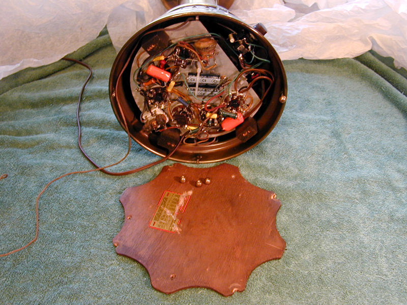
The wooden base plate is held to the blocks with wood screws and then
the plate is secured to studs in the base with four brass ball screws.
The scallops in the plate admit air for ventilation.
When I got to this stage of reassembly, I wondered if I had mislaid the
original feet for the cabinet. This is a heavy item and all of its
weight is born on the tips of the brass balls that
touch the table. That's a lot of stress on four tiny spots, but
when I zoomed in on other photos of these radios, I
could see the brass balls peeking from underneath, so I guess that's how the
set was designed.
If you own one of these sets, resist the temptation to put a cloth under
it, especially a thick cloth that might block the scalloped vent
openings in the wooden base plate. A tightly packed radio like this needs all
the ventilation it can get!
Final Thoughts
Here are two shots of the restored radio lamp, plus a photo of
my other radio lamp, the Mitchell
Lumitone.
Novelty radios aren't for everyone, but I like this set a lot. The
radio is discreetly incorporated into the overall design, and it's
a gorgeous lamp, even if you don't care about playing the radio.
For fun, I created an animated .GIF image showing the radio lamp
in different lighting.

Of the various radio lamps made
over the decades, I consider this design one of the most successful.
For a less successful attempt, check out the
Philco 53-706,
a clunky marriage between a lamp and a wooden radio, with
a clock thrown in for good measure.
|