RCA Model 14-S-7070G Television II (1957)


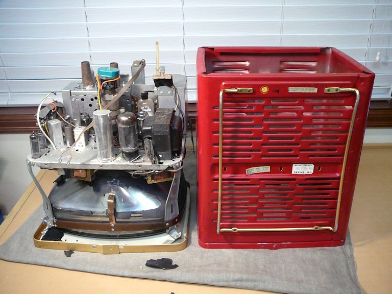
Long-time visitors to this website may think they're seeing double—haven't we seen this TV before? Nearly 20 years ago,
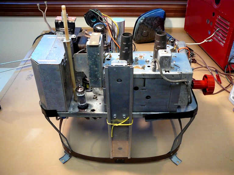
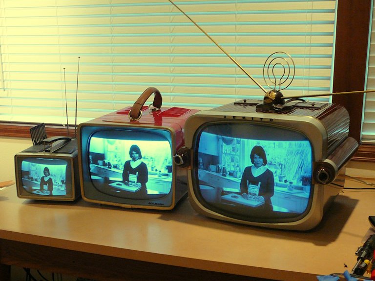
I restored a red RCA 14-S-7070G just like this one. These photos show my "new" 14-S on the left and
my first one on the right.

You can read about my first 14-S-7070G in another article.
I sold it to a fellow collector long ago, and sometimes felt a twinge of regret for selling it.
Finding an RCA 14-S-7070G
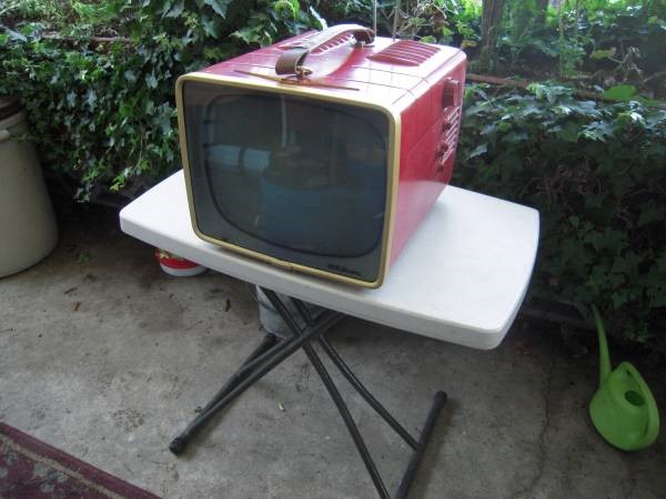
In 2016, I spotted this local craigslist ad:

It was the spitting image of the little red '57 Chevy TV that I sold years earlier!
Not only that, but it included a leather carrying handle, which was missing from my original.
Feeling nostalgic, I agreed to buy it for $50.
It helped that the seller was located on Whidbey Island, so we could bring along the family
dog and make a pleasant little day trip, including a ferry ride.
Description
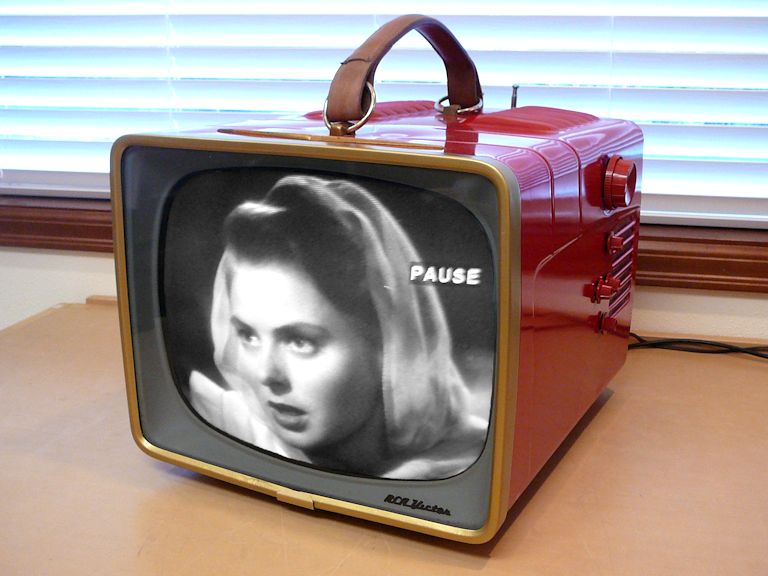
By the late 1950s, it became feasible to make a portable TV with a fairly large screen.
In earlier years, there were small 7-inch portables such as my Motorola VT-73,
but 7-inch CRTs were not very bright and their tiny pictures left a lot to be desired. By 1957, CRT technology
had produced new tubes like the bright, aluminized 14-inch 14RP4A
used in this set.
The resulting TV was inexpensive, easy to move around, and very watchable.
From the late 1950s through mid-1960s, many manufacturers offered sets roughly the same size as this one.
Whereas my 1946 630TS TV required 30 tubes, the 1957 14-S-7070 needs
only half as many: 15, including the picture tube:
| Tube |
Type |
Function |
| V1 |
6CB6 |
RF amplifier |
| V2 |
6U8 |
Mixer / Oscillator |
| V3 |
6CH8 |
1st video IF / Vert. mult. |
| V4 |
6CH8 |
2nd video IF / Sync. amp |
| V5 |
6AW8 |
Video output / Sync. sep. |
| V6 |
6AU6 |
Audio IF amplifier |
| V7 |
6DT8 |
Audio detector |
| V8 |
6AQ5 |
Audio output |
| V9 |
6AQ5 |
Vert. mult. / Vert. output |
| V10 |
6CG7 |
Horiz. AFC / Horiz. osc. |
| V11 |
6DQ6A |
Horizontal output |
| V12 |
6AX4GT |
Damper |
| V13 |
1X2B |
High Voltage Rectifier |
| V14 |
5U4GB |
Low Voltage Oscillator |
| V15 |
14RP4A |
Picture Tube |
In keeping with its low price, this set does not include automatic gain control (AGC) or
DC restoration, features that had become standard in higher-priced sets of the day.
Nevertheless, it makes a bright, sharp picture and performs well, overall. (Nowadays AGC,
which automatically compensates between strong and weak stations, is largely irrelevant, since
TV collectors typically feed their TVs from a source like a DVD player or cable
box, whose signal strength is constant.)
You can download this TV's Sams service manual free of charge from the Early Television Foundation
website.
It is Sams Set 354, Folder 16.
This article refers to components by their Sams part numbers.
First Look
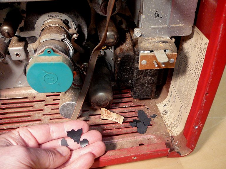
As with many old TVs, this one was dirty inside, and one corner of the cabinet was slightly bent,
as if it had been dropped. Perhaps that happened when the original leather handle broke; this
handle is a newer replacement.
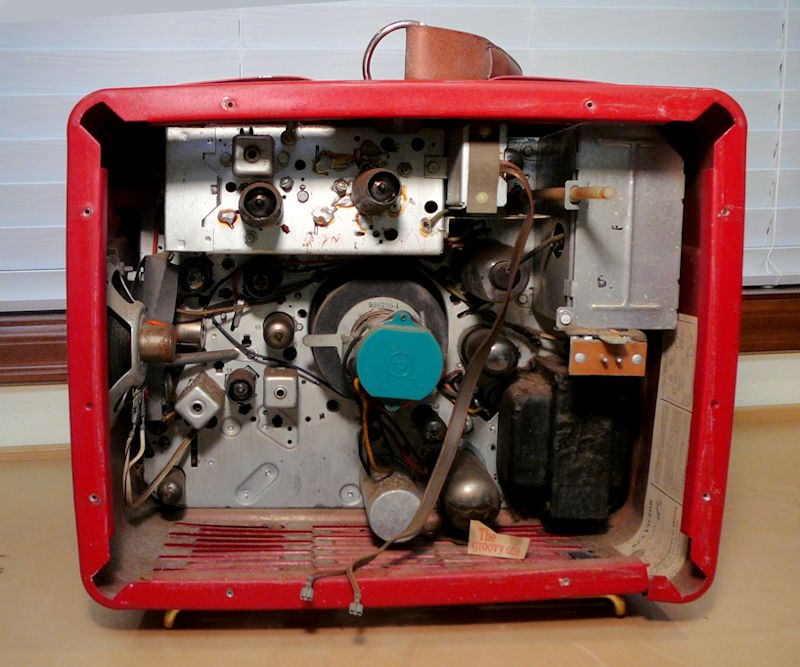
A cut-out piece of paper labeled "The Groovy One"
suggested that this TV belonged to a teenager at some time. Maybe this was used in a
bedroom or rec room, while the fancy family set was watched in the living room.

The flakes of black material are remnants of the picture tube's conductive "aquadag" coating.
Luckily, it's easy to spray on a new coat of aquadag, so this TV will have a fighting chance as long as its
CRT isn't a dud.
Let's get started!
Electronic Restoration
As with every TV and radio project, I'll begin by doing a general clean-up,
testing the tubes, and cleaning the set's controls, tasks you can learn more about in the article,
First Steps in Restoration.
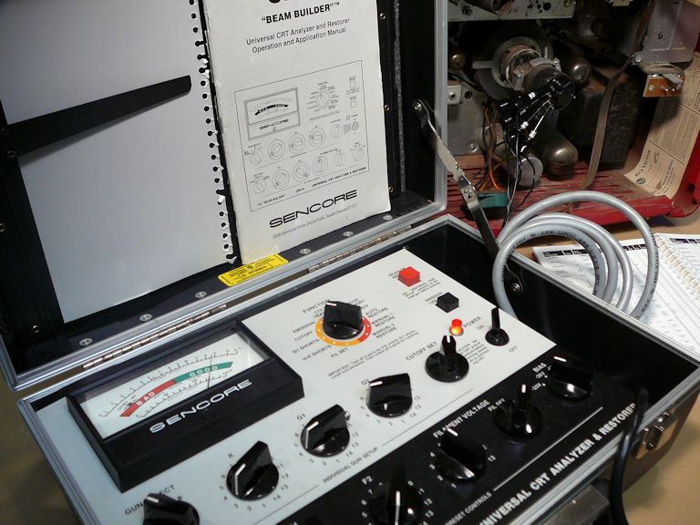
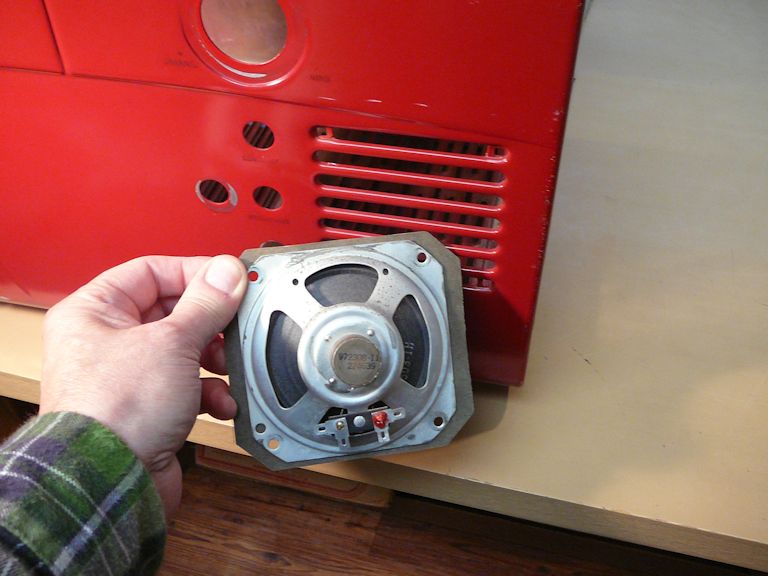
The first item to check is the 14RPA picture tube. If it's no good, a replacement could cost twice
what I paid for the TV. My Sencore CR70 tester shows that it has very strong emission, which bodes
well for a successful restoration.

I'll check the other tubes after I pull the chassis out of the cabinet. Those are much cheaper,
so if one or two need replacement, I'm only out a few bucks.
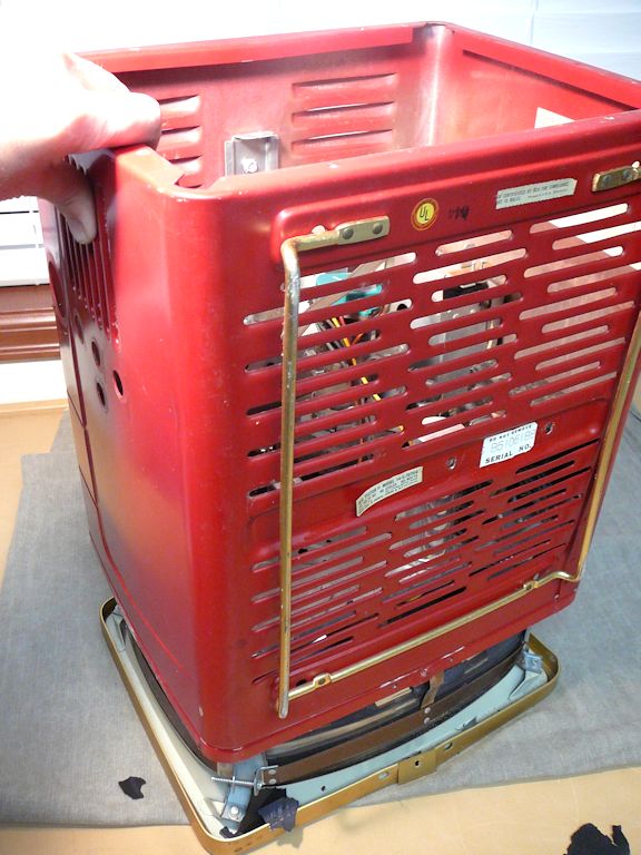
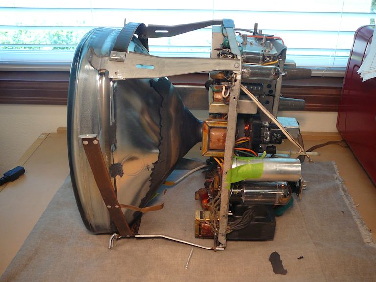
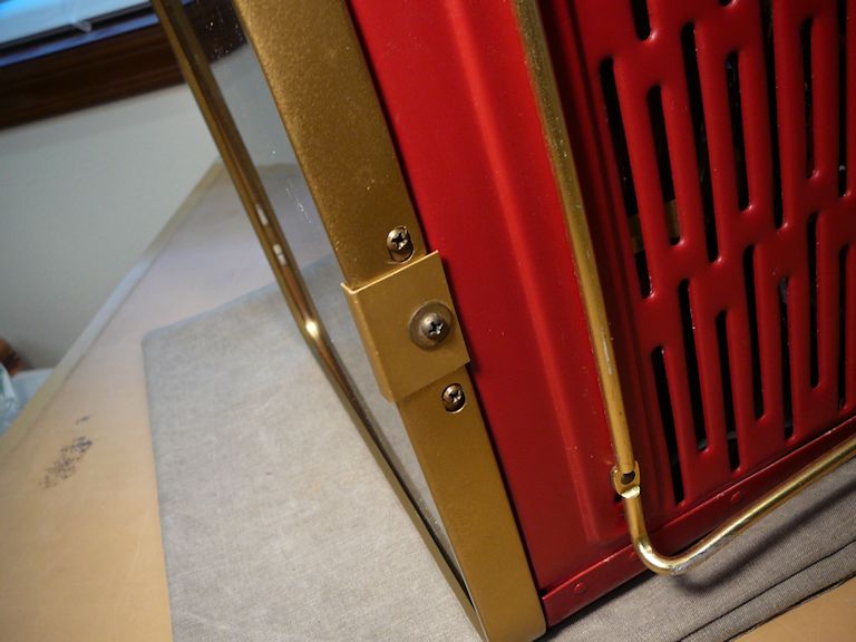
To remove the cabinet, you detach the gold trim piece from the front and lay the TV face-down on a soft pad.
Next, remove three screws from the bottom of the cabinet and remove this single screw from the inner supporting rail:

It's easier to reach that screw if you temporarily remove the tuner tube, as in the previous photo.
Then you can slide the cabinet up and away from the chassis.

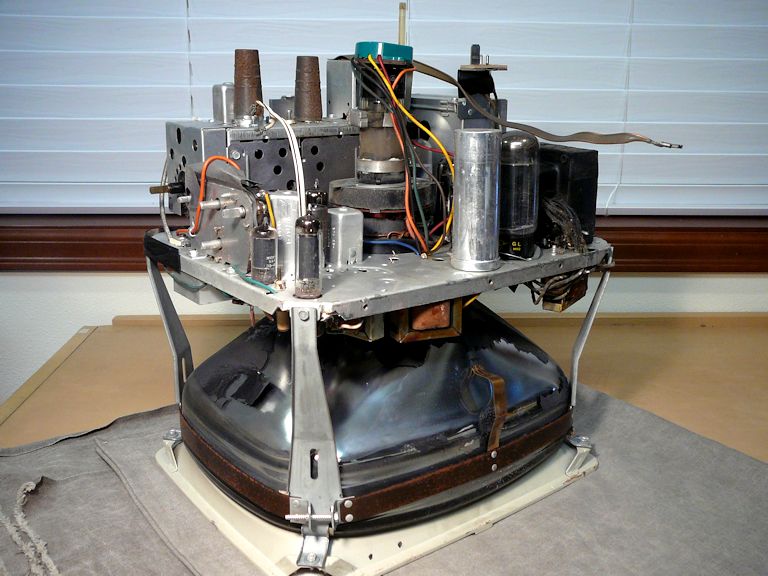
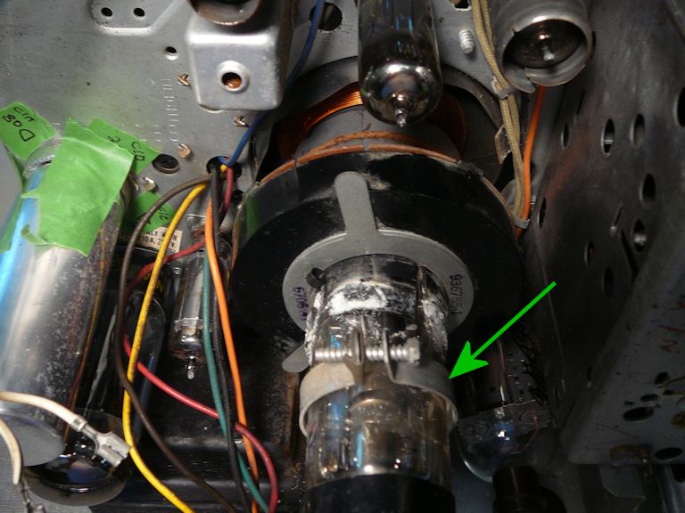
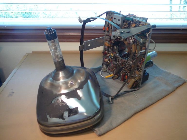
In the second photo, you can see that the picture tube continues to shed flakes
of black aquadag from its bell. It will definitely need a re-spray!
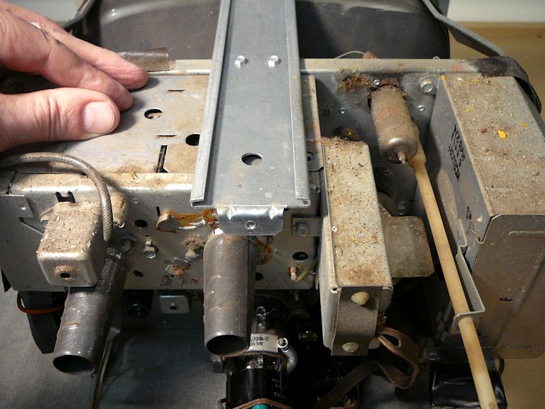
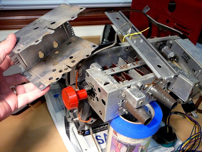
Here's a view of the inner supporting rail on top of the chassis. Yes, there's dirt to clean
up, but I have seen much worse.
As in my other 1950s portables, like the RCA 8-PT-7030 or
Zenith T1816R, the designers saved space by wrapping the
chassis around the neck of the picture tube. This made the set compact, but it
complicated the serviceman's life. Many components are crowded near the picture
tube's bell, as we'll see in the next photos.
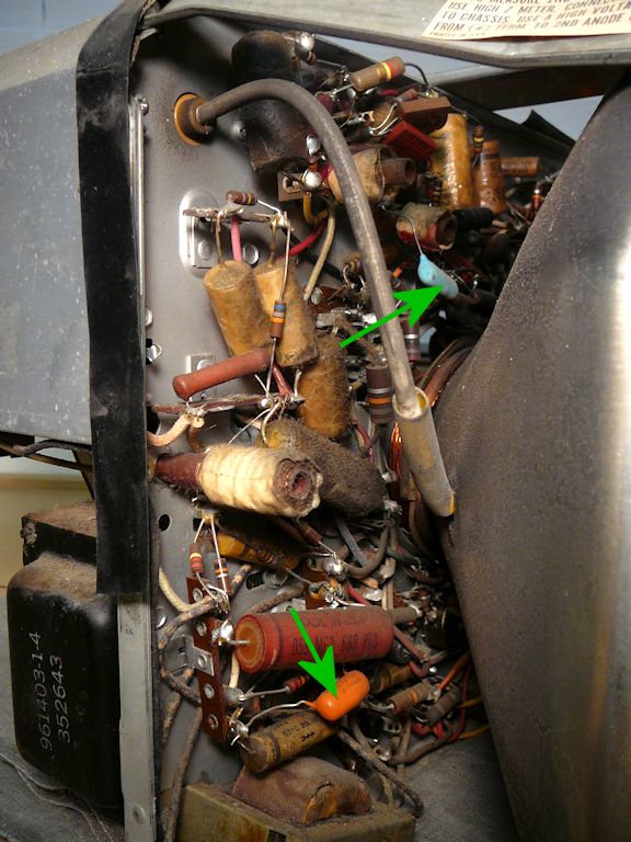
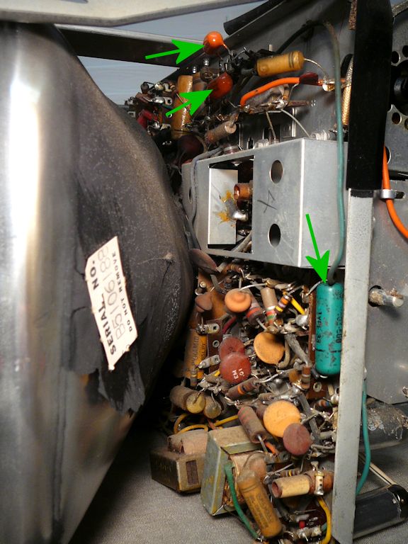
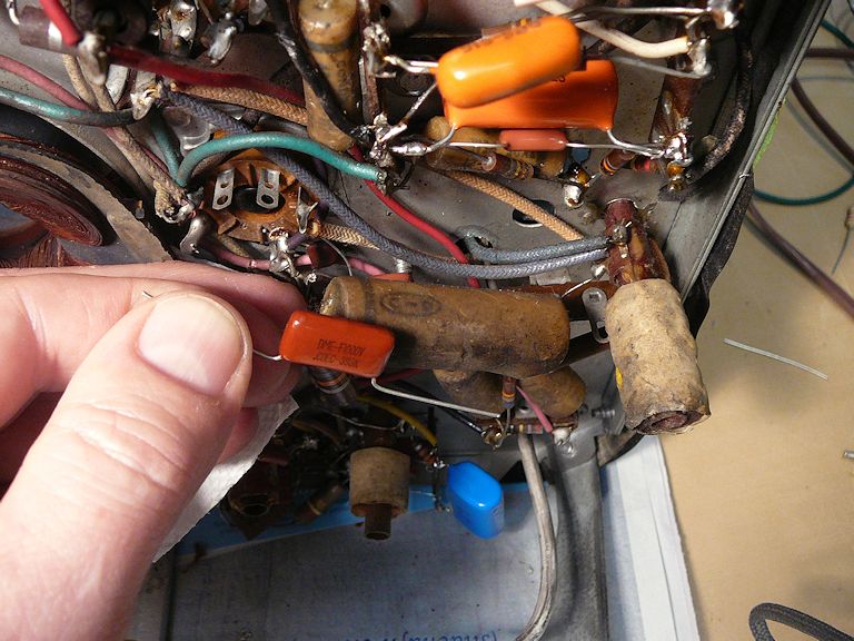
These pre-restoration views show that the TV was serviced, possibly more than once.
Amidst the usual assortment of original tan paper capacitors, there are some newer (probably 1960s)
replacements: some "orange drop" style caps and a green plastic-coated paper cap.
Plastic-coated caps are short-lived and I'll replace them along with the
paper ones in the initial recapping. Orange drops are generally more reliable, so I'll
leave them alone for the first round. Perhaps the TV will work acceptably with them in place.
In the second photo above, the serial number tag on the bell of the picture tube matches
the tag on the bottom of the cabinet: B5016188. Despite some dirt on the outside, this
set has its original CRT, which retains strong emission. That's the sign of a low-mileage
television—a perfect candidate for restoration!
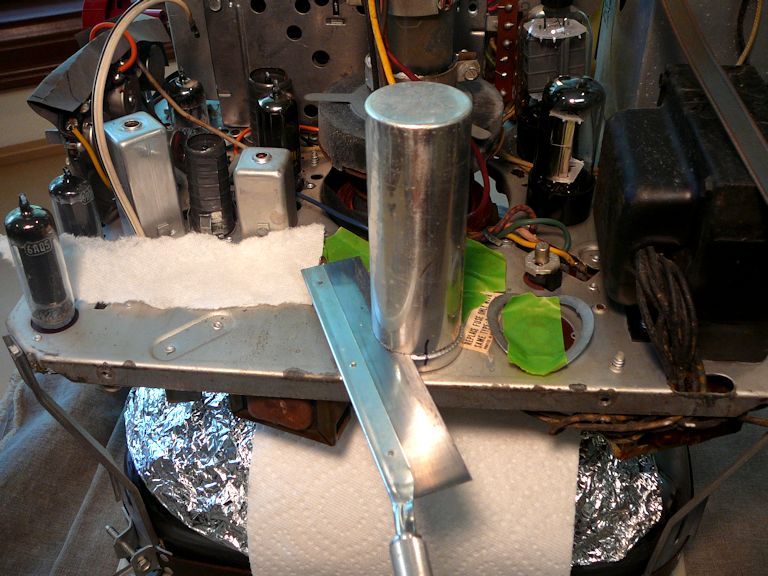
Our chassis looks more civilized after a thorough cleaning:
Notice how much of the black aquadag coating has fallen off. In the previous photo, the
springy L-shaped part reaching up from the chassis frame should be touching black aquadag on the
CRT's bell. Instead, it's resting on a wide expanse of glass.
Cleaning didn't require anything exotic, just some paper towels, Windex, rubbing alcohol
for the greasy spots, and an old toothbrush for the crannies. Now let's check those tubes.
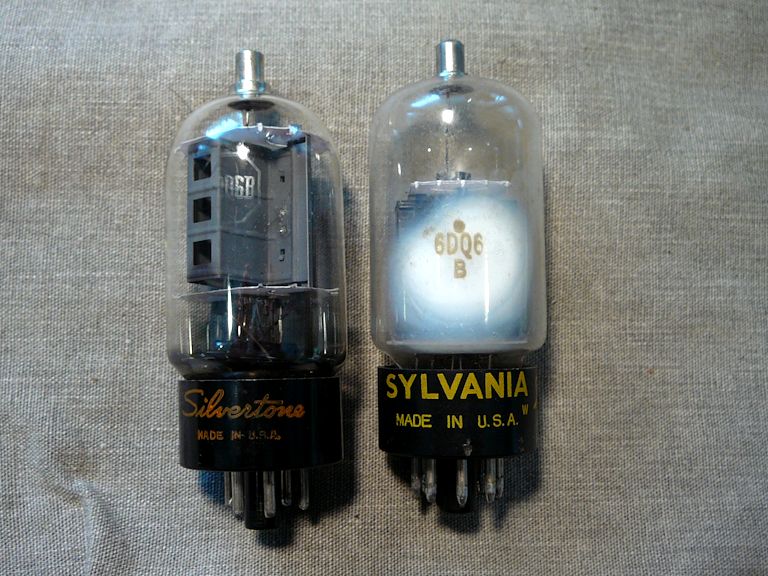
I could see at a glance that the 6DQ6B horizontal output tube was dead. Its internal "getter" material
has turned chalky white, a sure sign that air leaked inside and ruined the tube elements.

Fortunately, I had a few replacement 6DQ6B tubes in my stash, so this won't slow us down.
As frequently happens, all of the other tubes passed testing with flying colors.
Tube replacement was the most common form of service for these TVs, and it's
notable that the dead output tube was itself a replacement: a Sylvania brand, not
RCA. Either this TV runs that tube hard or there was some other, undiagnosed problem that
caused two HOTs to fail.
Replacing Electrolytic Capacitors
The next phase of restoration—capacitor replacement—often takes as long as
every other step of the project. You can read about the basics in my
recapping article elsewhere in this website. In this
section I'll only point out a few highlights.
The most logical place to start is with the electrolytic capacitors in the power supply, since nothing
else in the TV can operate until the power supply is healthy. This set uses four electrolytics: two
for power-supply filters and two others in the audio output circuit.
Looking back at my first restoration of this model, I see that I took the easy way out with the
electrolytic can. Rather than empty the can and "restuff" it with new caps, I
disconnected it and wired new ones under the chassis. The TV will work either way, but this
chassis is already pretty crowded, so this time I decided not to add to the under-chassis clutter.
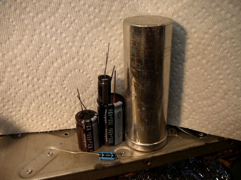
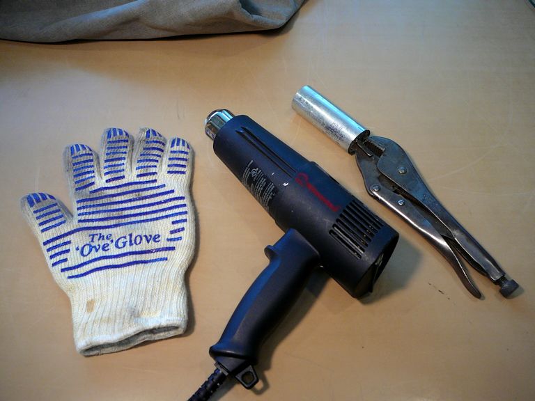
Here's a quick look at how I restuffed the can on this set:


Executive summary: I cut off the old can and pulled out its innards after softening the tarry internal adhesive with a heat gun.
I drilled holes in the can's base next to the existing terminals, threaded the leads for new capacitors through
those holes, and soldered the new cap leads to the terminals. Later, after I was ready for a power-up test, I checked
the TV's operating voltages and finally epoxied the empty can back onto its base, so the TV looks original again.
(Don't worry—after the fifth photo was taken and the connections double-checked, I strapped the new caps together
with electrical tape to fit neatly into the can.)
If you visit my recapping article, you'll find links to much more detailed descriptions of
electrolytic can replacement, with the pros and cons of various methods.
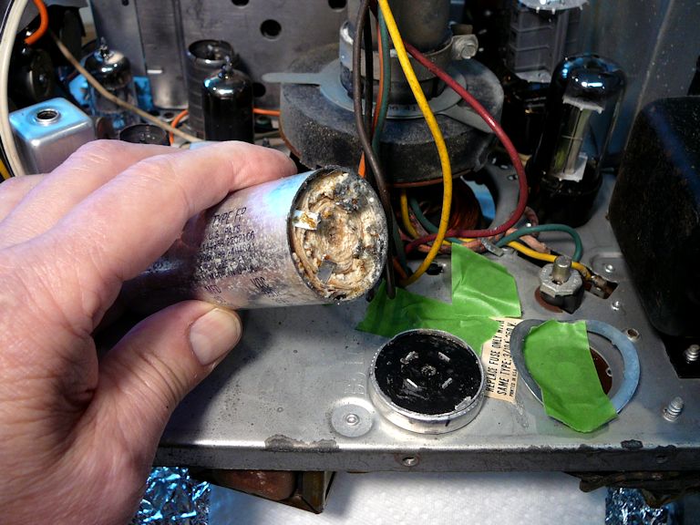
When using this method, make sure to correctly identify the capacitor terminals. The power supply
is one area where you don't want to mix things up.
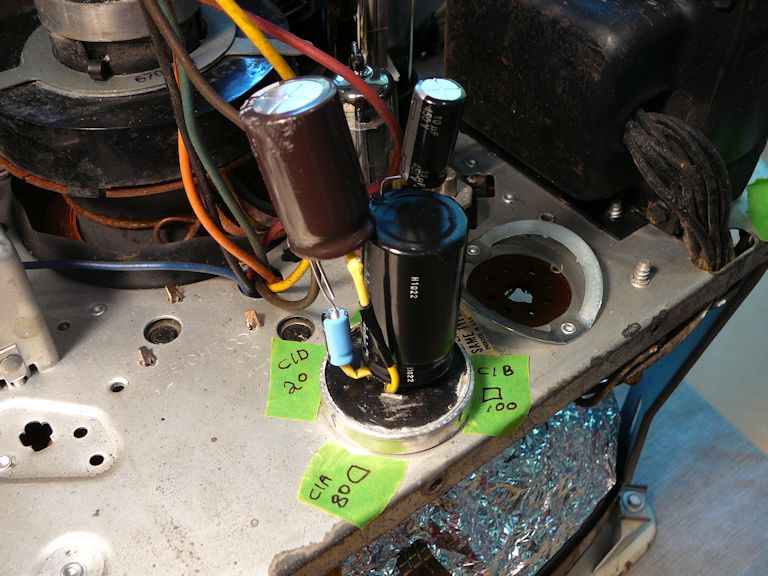
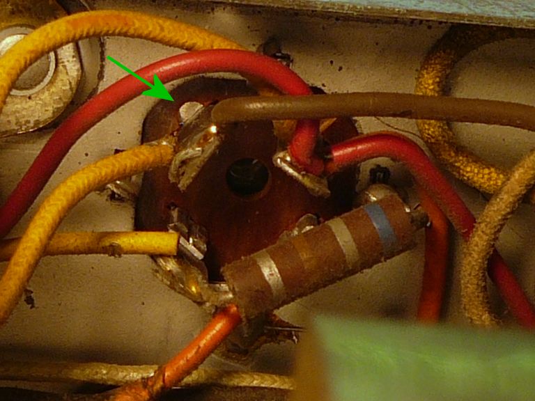
In the following photos, the first one shows the underside of the
can base; an arrow points to one of the geometric shapes (there, a semicircle) that identify each terminal. The second photo shows
how I temporarily labeled each terminal from above, as a safeguard against mistakes.

Even though I have replaced dozens of electrolytic cans, there's no penalty for being careful!
Removing the Picture Tube
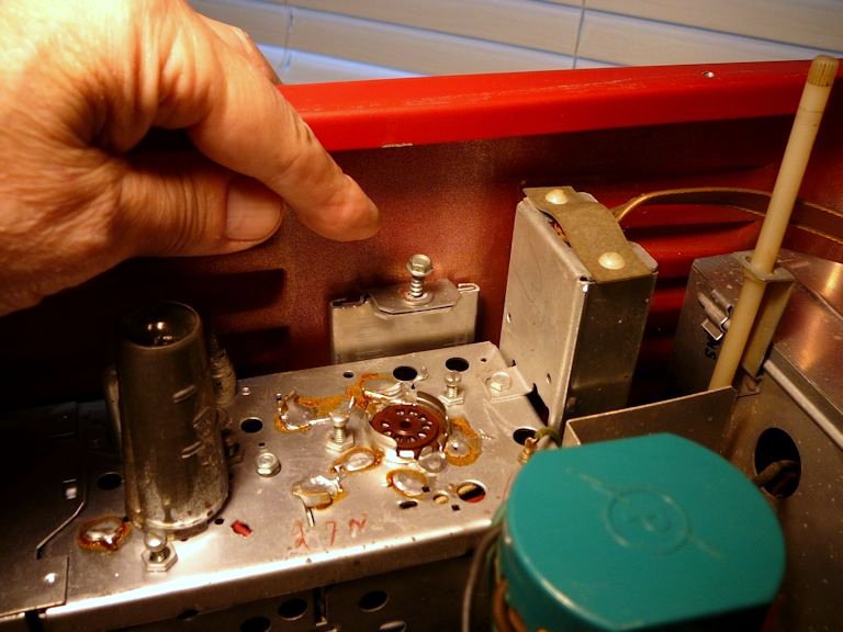
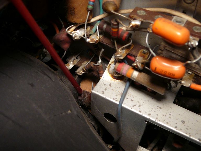
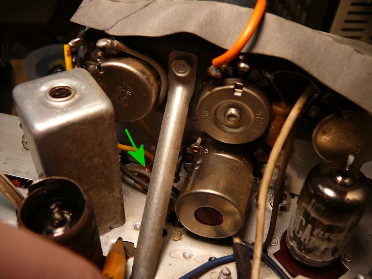
The next step would normally be to replace the old paper capacitors, but this photo shows
why I decided to remove the picture tube first.

The red tool points to one end of a crusty paper cap that's barely visible between the
picture tube bell and the chassis. The cap's other end is completely inaccessible.
Reaching this one—and some others near the bell—will mean removing
the picture tube, or at least loosening the yoke and sliding the CRT forward far
enough to permit access.
Start by removing the high-voltage lead from the little recess on the CRT bell
that connects to the CRT second anode. Many such leads have little rubber insulating cups on
the end, but this one apparently never had a cup:

If the TV has been powered up recently, discharge any residual high voltage from the CRT
by using a clip lead to make a short circuit between this lead (still in the CRT)
and the chassis. Then you can safely squeeze the prongs of the lead and pull it free.
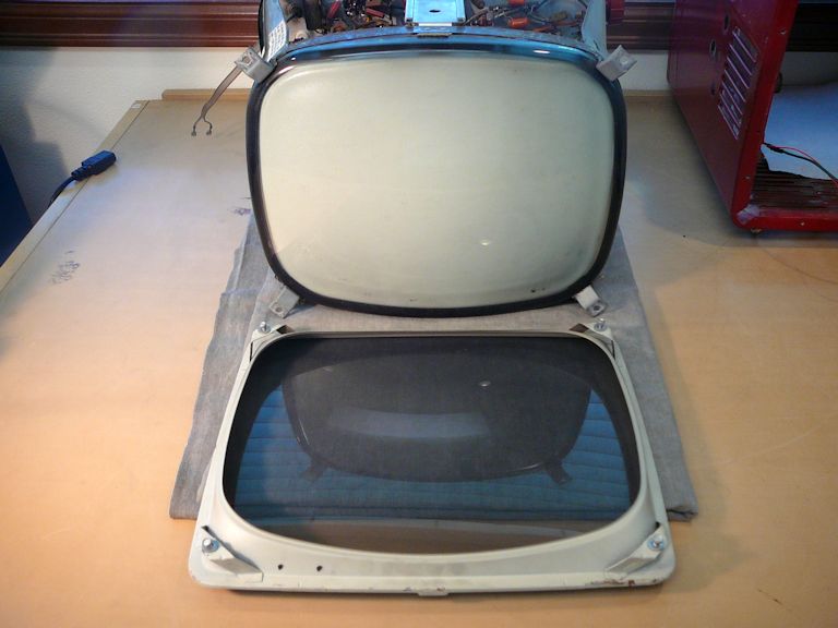
The screen cover is secured to the chassis by four screws in the front. I laid
the TV as shown to remove it:

Before loosening the CRT from its mounts in the front, you'll need to remove everything
from its neck in the rear. The next photo shows those three items. First is the CRT socket, which
unplugs from the tube base; grip the base with one hand while you gently remove the socket, to
avoid tearing the base off in the event that its glue has loosened. Second is the ion trap
magnet, a little spring-loaded part that slides back over the base. Last is the black yoke
with its two movable flat metal tabs. (The tabs can be rotated to center the TV image on
the screen.)

The yoke is held onto the CRT neck with a clamp. In the following photo, I have removed
the CRT socket and ion trap magnet, and loosened the yoke clamp enough to slide it off.

Now we can loosen the front CRT strap and draw the CRT out. For this step, I laid
the TV on its side, providing access to the strap mounting screw.

Make sure that the chassis is sitting securely on the work table before you pull out
the picture tube. In this set, the sleeve of the plastic yoke cover was very tight, after nearly sixty years of
being clamped around the tube neck. Eventually, I removed it by unsnapping the cover from the yoke frame
and slowly wiggling it over the tube base. Then the CRT neck could easily be withdrawn frontward through the
yoke.

At last, the CRT is out and we can proceed with recapping.
Pulling the picture tube is easier than you might think from
reading this description, but it's important to work with care. The
CRT neck is the most fragile part of the tube, and in this set's design
the CRT bell—specifically, the rigid, heavy portion near the face—is
an important structural member of the chassis.
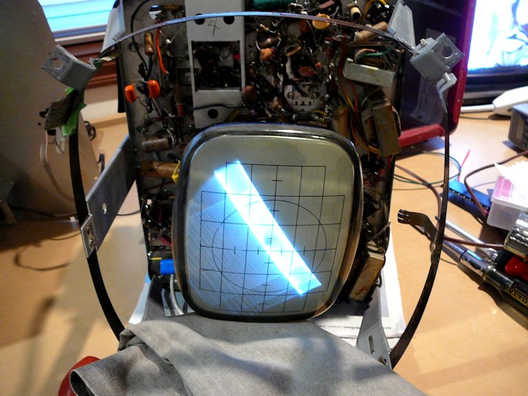
First Power-Up
With new electrolytic caps in place,
I installed my 8XP4 test CRT to make
some basic voltage checks and observe how well (if at all) the TV performed.
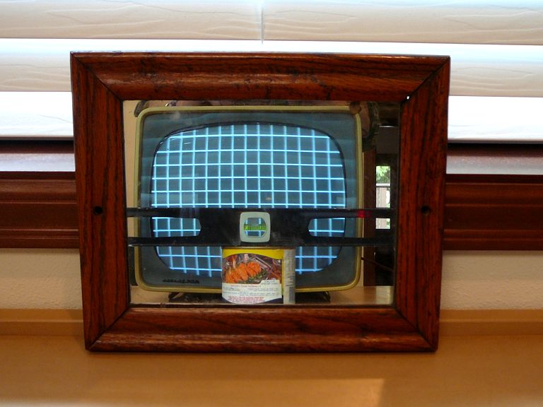
Here's the result:
Many things are wrong with this TV picture, but the overall result is encouraging.
The picture tube lights up, showing that our high-voltage output is in the
right ballpark and B+ voltages are also present. Vital components such as the
flyback transformer and yoke are functional, and we have both vertical and horizontal
deflection. I could also hear near-normal sound through the speaker.
On the demerit side, there's no hint of the TV signal, only bare lines.
Vertical and horizontal sweep are operating but deficient, so the TV image is unable
to fill the screen. (The image is tilted because I hadn't bothered to straighten
the yoke in this brief test.)
Full speed ahead! The TV is working as well as might be expected at this stage.
The remaining problems should clear up as we replace the bad paper capacitors.
Replacing Small Capacitors
Installing the small caps was a repetitive process, so I won't show that in detail.
Refer to my recapping article for general info on that topic.
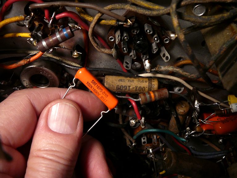
This TV uses a few paper capacitors with higher-than-normal voltage rating. It's
important to match or exceed that rating for reliability's sake.
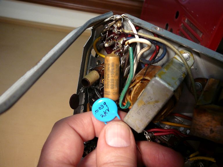
The next photos show these components: C62, a .001/1600V cap in the vertical output
circuit, C47, a .0039/1000V cap in the audio output circuit, and C75, a
.039/1000V cap in the high-voltage output circuit:


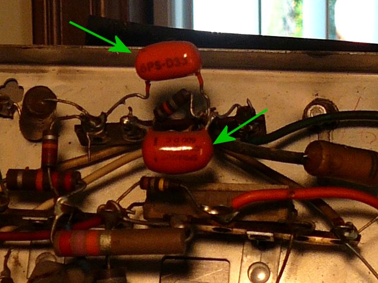
Earlier in this article, I mentioned a few orange drop type caps that I planned
to leave alone for the time being. These include C54 and C55, caps in the vertical
integrator circuit that extracts vertical pulses from the sync signal:

When replacing components en masse, it's prudent to play the TV periodically
during that process, to make sure you haven't mis-wired something or installed a
component of the wrong value. Here's what I saw at this time,
when I had replaced many paper caps but left C54 and C55 in place:
For this test, I temporarily reinstalled the big CRT. Many things have improved, but
we still have a vertical problem. The image deflects fully, but it locks in the wrong
place, resulting in a split screen.
I quickly replaced C54 and C55, the vertical integrator orange drops, and
the problem disappeared:

Orange drop (dipped mylar) caps were generally more reliable than paper caps,
but it has been 50 years, give or take, since those old orange drops were installed,
and time has taken its toll. I'll replace the few remaining orange drops and finish off
the papers.
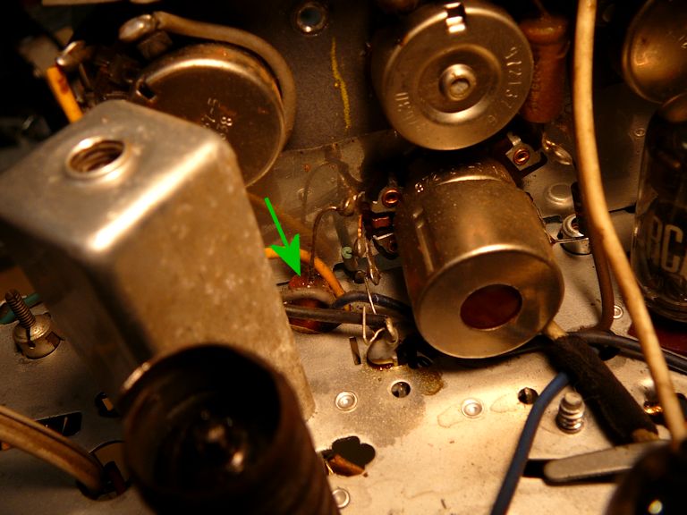
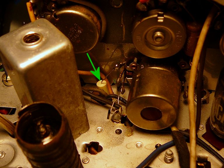
Here's one last cap that's easy to overlook. It is C42, a .0015/600V cap that couples
the sound signal from the audio detector to the volume control. Notice how the capacitor body
snakes through a little hole in the chassis:

Things are even more obscured on the other side of the chassis, where C42 connects
to a terminal on the volume control. I can reach that end after I remove the little
metal brace that secures the panel holding the TV's controls.


The new cap is smaller than the original and fits neatly into the cramped space:


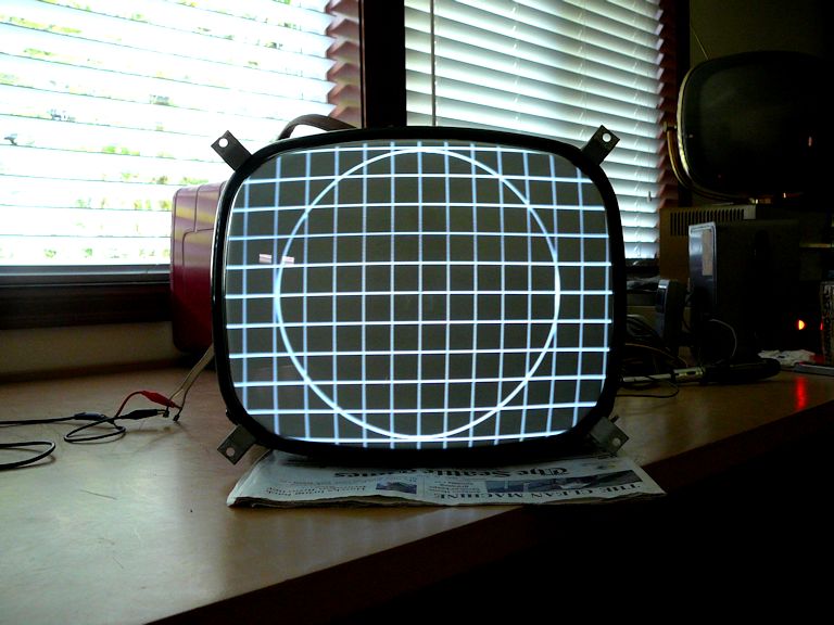
The basic recap is complete. My TV has excellent audio and the picture looks good
enough to make preliminary adjustments to the screen geometry (height, width,
linearity, and centering):
Notice that I reached this stage without exercising any deep knowledge of
electronics or television theory. I simply identified the bad capacitors on the
schematic and parts diagrams in the service manual, and replaced them with
modern equivalents. The TV may still have other problems—and we'll get to one
in a moment—but bringing it to this state was straightforward.
Checking and Replacing Resistors
In the course of recapping, I also tested many of the TV's resistors,
watching for any that diverged more than 20% from the value given in the schematic.
My notes show that I replaced about a dozen resistors in this set. Most of them were in
the vertical and horizontal sweep circuits, where precision is generally more
important than in less finicky sections.
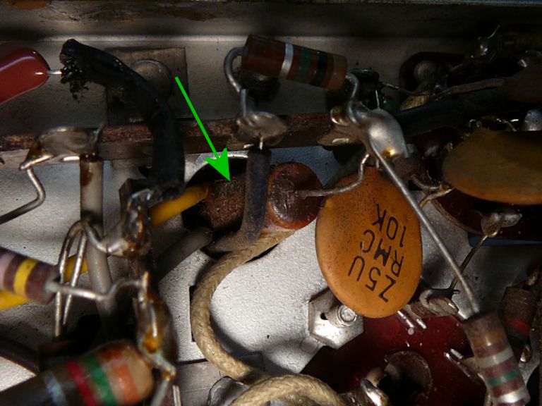
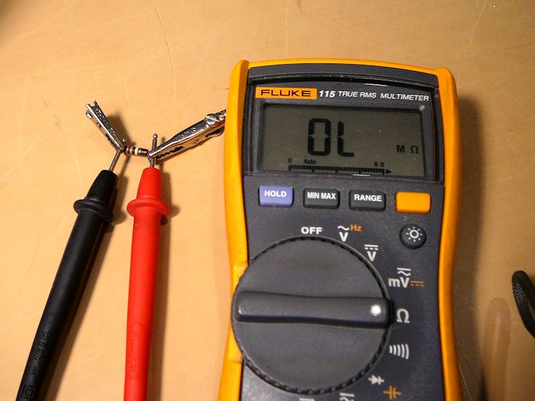
One exception was R29, a 180K resistor that connects the Brightness control to the 240V
voltage source. While testing the TV during recapping, I noticed that the Contrast control
worked as expected, but Brightness seemed unresponsive. Turning it
all the way in either direction had little, if any, effect.
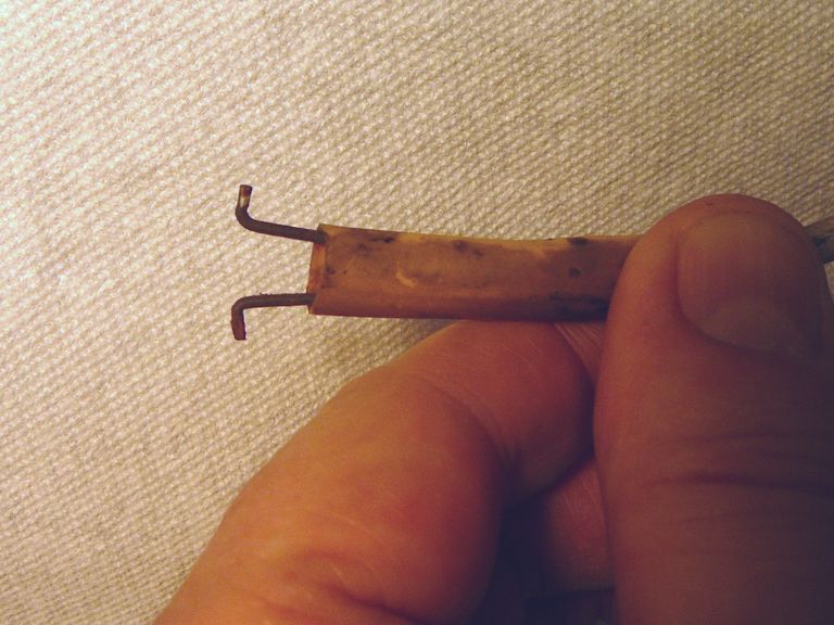
Checking that resistor solved the mystery: it was open (measuring infinite resistance).
Here is R29 on the bench after I clipped it out for replacement:

Replacing that resistor instantly cured the Brightness control, which operated smoothly over
its entire range.
Bench Test
Satisfied that I had replaced the most obvious bad components, I glued the electrolytic can
back onto its base and turned on the TV to bench-test it for a couple of hours. As long as
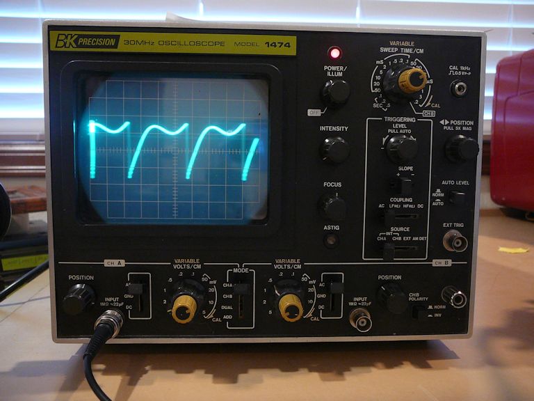
it was playing, I hauled out my pattern generator and oscilloscope, to observe waveforms
at some key points. Here's a horizontal waveform:

The waveforms looked good and the TV's performance was stable, so I set the chassis aside
to work on the cabinet and recoat the picture tube's aquadag.
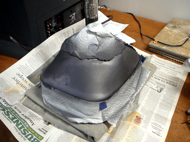
Renewing the CRT's Aquadag Coating
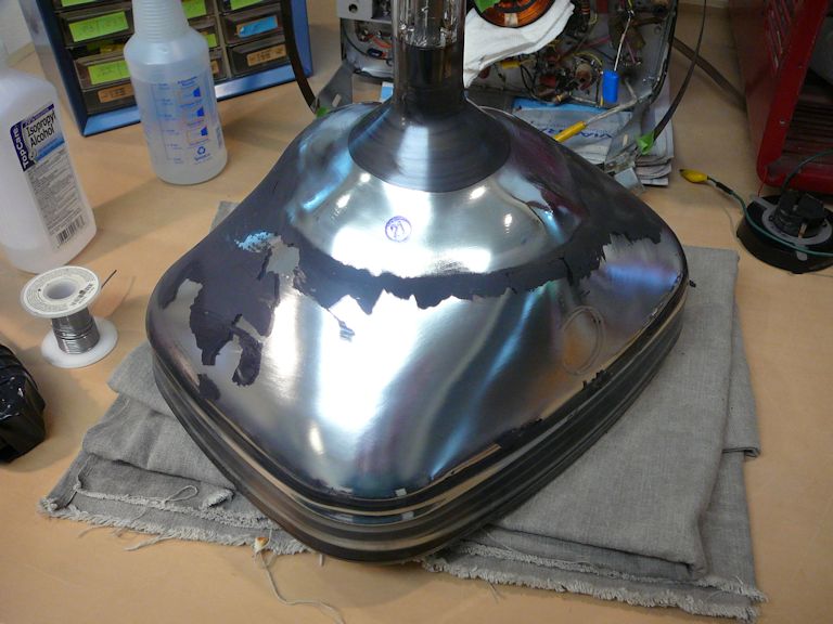
As noted earlier, this TV's picture tube had a severe case of dandruff. Nearly half of its
original black aquadag coating had flaked off.
Aquadag is a thin layer of sprayed-on
graphite or similar conductive material that serves as half of a filtering
capacitor in the CRT circuit. The other half of the capacitor is a matching
conductive layer inside the tube itself. The outer aquadag layer is grounded when you install
the tube and it touches a springy connector mounted on the chassis.
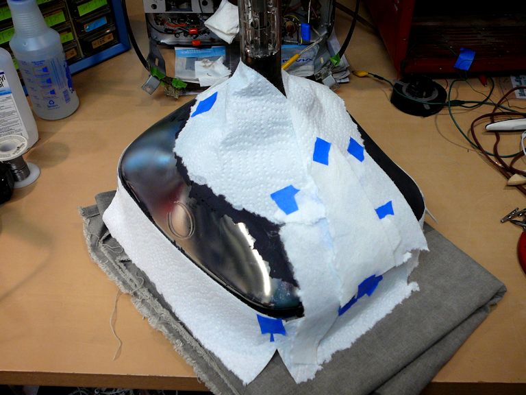
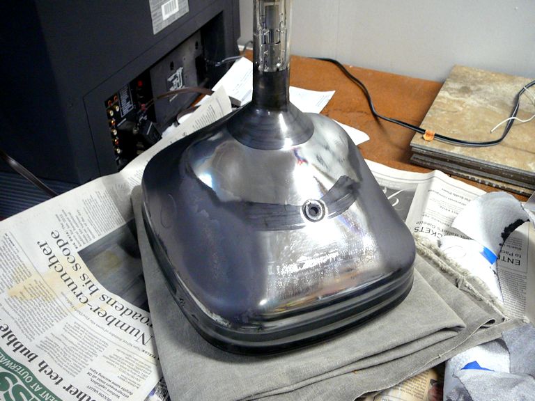
Refreshing the aquadag is easy. Buy a spray can of
Aerodag or
Slip Plate and
you'll have enough to redo many CRTs. Clean the CRT bell carefully (I used isopropyl alcohol),
mask off the areas that you don't want to cover, and spray on a few coats.


In the fourth photo, notice how the masking kept the aquadag well away from the
little recess in the CRT bell where you insert the HV lead. You really
don't want to create accidental conductive paths to ground at that spot.
Cleaning the Tuner
During the bench test, I observed the TV using some previously-untried
channels and noticed that the tuner needed cleaning. For some channels, I
had to wiggle the tuner to bring in clear reception, a sign of dirty or oxidized
internal contacts.
I have never liked the wafer-style tuners that RCA used in these years, such as the
one in this TV as well as my CTC-11. I prefer the more
robust turret tuners, like the one in my CT-100 color set.
Anyway, this one is what it is. With luck, a careful cleaning will make it serviceable for
years to come.
Whenever you open up a tuner, remember the maxim, "Less is more." Apart from
moving contacts, the components inside tuners are extremely reliable; I have never
needed to replace any component inside a tuner. The positioning and lead dress
of those components is critical, too. If you clean a tuner, touch
only the parts that you're cleaning and leave everything else alone.
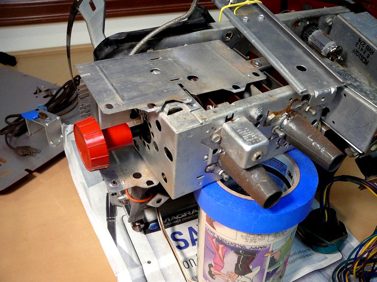
On this TV, it's easier to loosen the tuner mounting screws with the CRT removed. Note that you can stand
the chassis up on its "legs" when the CRT is out, as long as you have refastened
the screw that secures the CRT front mounting strap.

It's possible to give this tuner a basic cleaning without unsoldering all of its
connections. Unscrew the tuner cage from the chassis frame, swing it out from the chassis
still attached by its leads, and then unscrew and slide off its cage cover to access the innards.

Be sure to support the tuner to avoid stressing its leads during this operation.
When cleaning a tuner, don't use anything abrasive on the contacts or
spray the cleaner indiscriminately inside the tuner, which can soak into phenolic parts
and create havoc. You want to carefully hand-apply cleaner to the contacts—and
only the contacts.
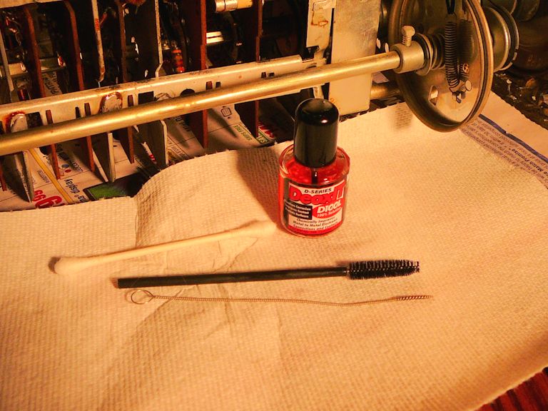
The next photo, from a different restoration, shows what I generally use for contact
cleaning: liquid DeOxit along with Q-tips (often, many Q-tips). You can also use soft plastic brushes, if needed.
The thin stainless brush shown at the bottom of the photo is best reserved for cleaning
the holes in tube sockets.

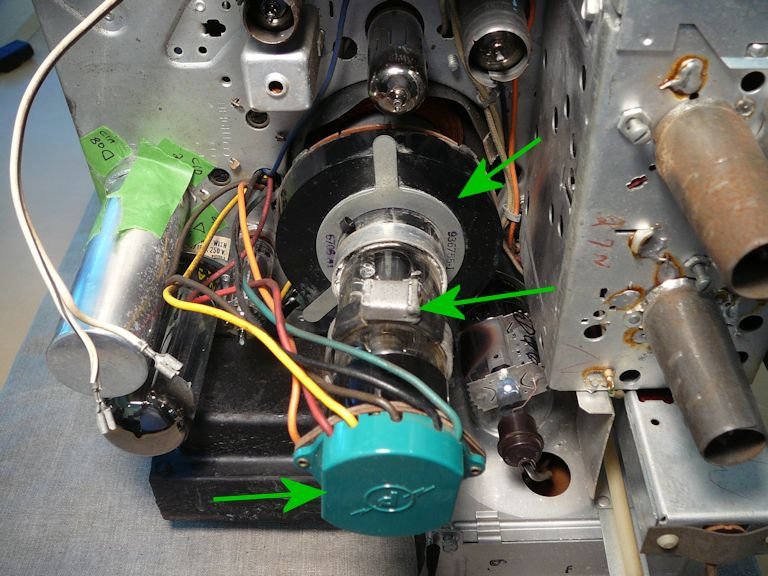
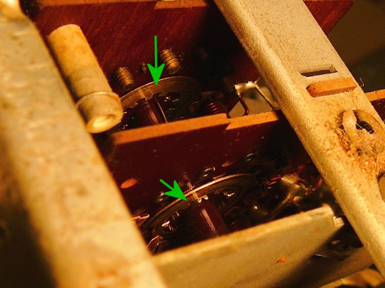
The following photo gives a peek inside the 14-S-7070 tuner. Arrows point to important contact
surfaces. In this post-cleaning view, they are clean.

After the cleaning, I applied a small amount of lubricant to the tuner's detent
mechanism and then buttoned it back up. Now the tuner operates smoothly and
receives a clear signal.
Cabinet Restoration
With the electronics under control, I turned my attention to cosmetics. This TV's cabinet
is in decent shape, with little scuffs and scratches consistent with its age.
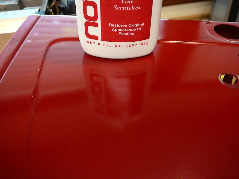
Repainting would make it look new, but that would obliterate the lettering around the controls,
which I'd rather preserve. I decided to polish it with Novus Plastic Polish #2
and declare victory. The Novus deepened the color and brought out some luster.

I had feared that the slight bend in the rear of the cabinet would be hard to remedy, but
the cabinet metal is light. It straightened easily with hand pressure and a little
tapping from inside.
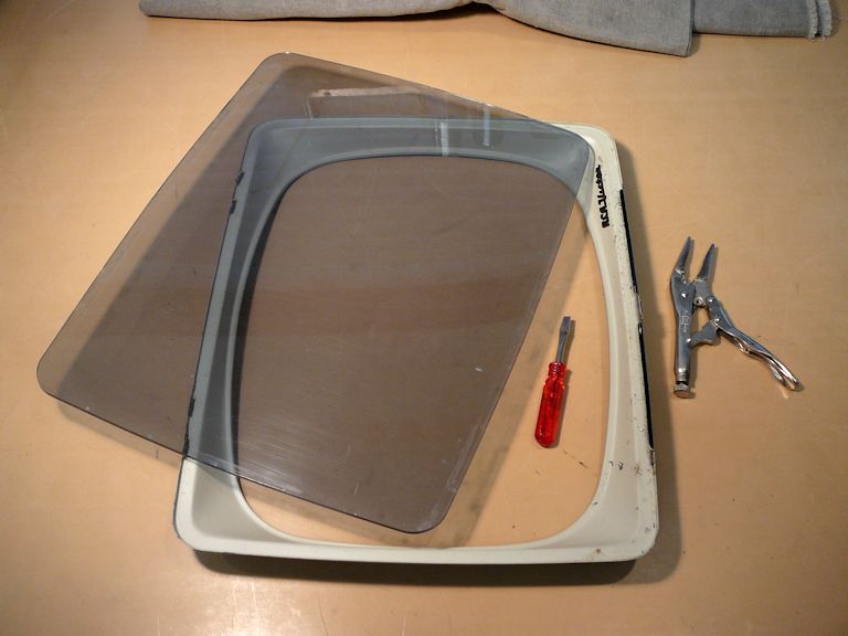
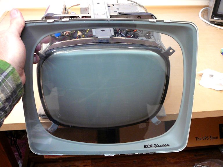
The screen cover on this TV is made of grey-tinted Lucite, and like most Lucite covers, it
has visible scratches. You could polish the front without removing the cover from its metal frame,
but the narrow spaces between the inside of the cover and its frame were full of dust and grime,
and I wanted to clean that area thoroughly.
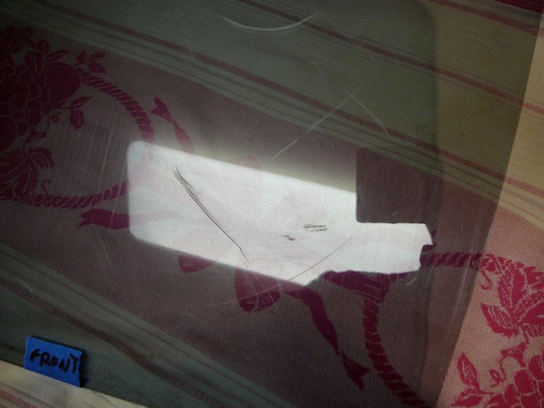
To remove the Lucite cover, bend up two metal tabs on the top of the frame and slip the cover out.
Yes, my cover definitely has some flaws.

The next photo shows the Lucite piece after I made a first
pass over the left half with 1000-grade paper. (Go to an auto supply store or hobby store for
sanding paper in very high grades.) This looks awful—my wife took one look and said
that I ruined it!—but I have only begun this multi-step process.

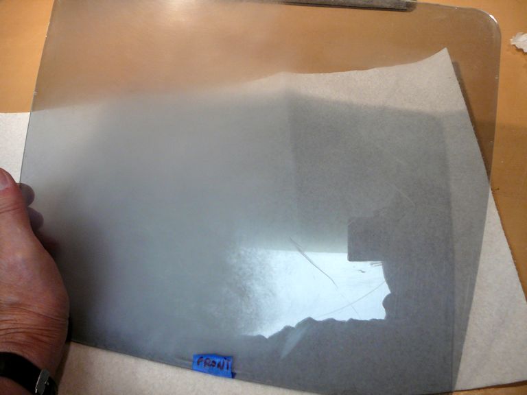
After wet-sanding the whole surface with 1000-grade paper, I repeated the process with
wet 2000 paper, and then made two more passes with wet 2000. After that, I switched to
soft cloths and Novus Polish #3 and made three (or was it four?) passes with that. Next came the
finer grade of Novus, good old #2. I forget exactly how many times I polished it with Novus #2,
but eventually it looked right. I washed the cover in warm soapy water, cleaned the metal frame,
and put it back together.
Removing the scratches took a lot of sanding and polishing, but it's worth the effort to me.
Nothing is more annoying than to spend dozens of hours restoring the electronics, only to notice
a big, fat scratch on the screen after you put the TV back together.
Reassembly and Final Tweaks
Time to reassemble!


Now I can make the final screen geometry adjustments, using my Philips PM 5518 pattern generator.
A builder's level helps to ensure that the yoke is straight.


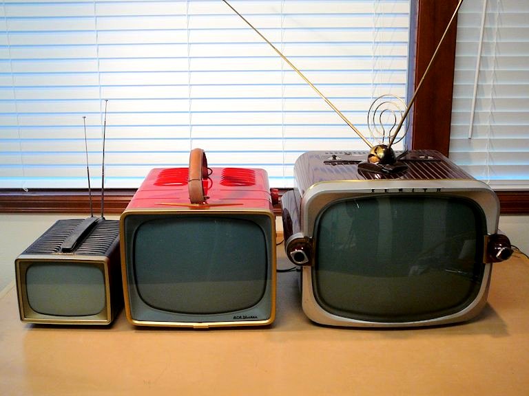
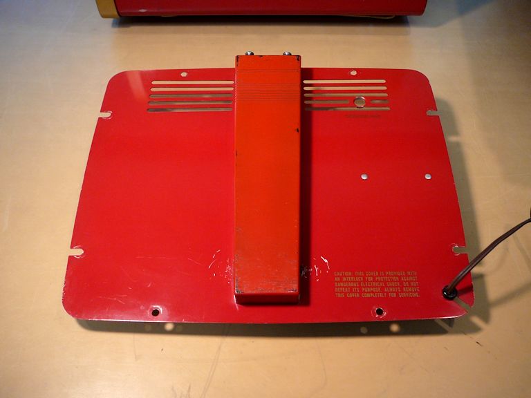
Lastly, the rear cover. Unlike my first 14-S-7070G, this one includes the optional
"piggyback" accessory antenna:

Just for fun, I brought out two other 1950s metal-cabinet TVs for comparison: my
1956 RCA 8-PT-7012 and the larger 1955 Zenith
T1816R.

My workbench didn't have room to include a 7-inch TV, but of course that
screen would be even smaller than the 8-inch screen of the 8-PT-7012.
Final Thoughts
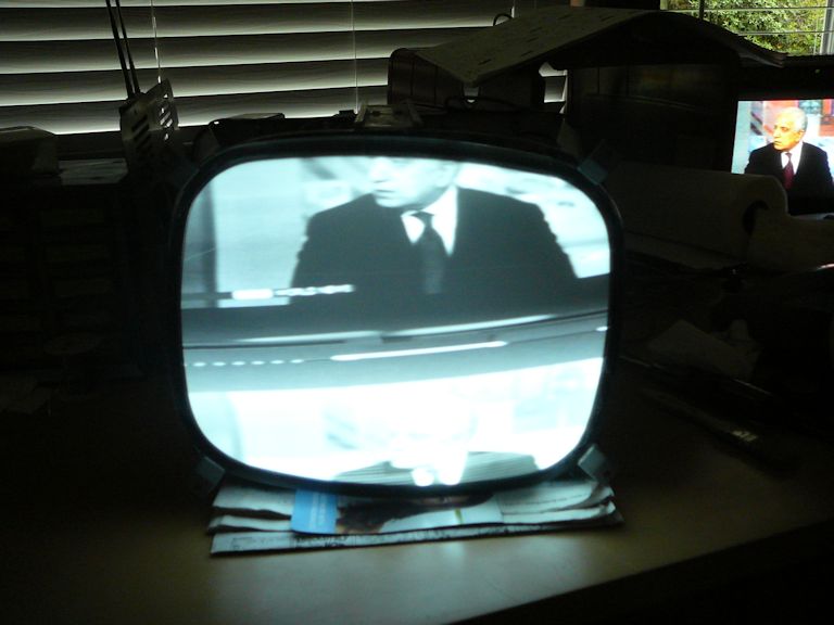
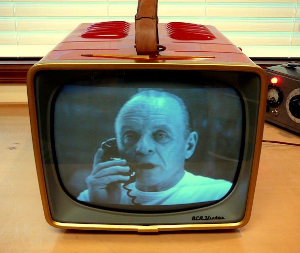
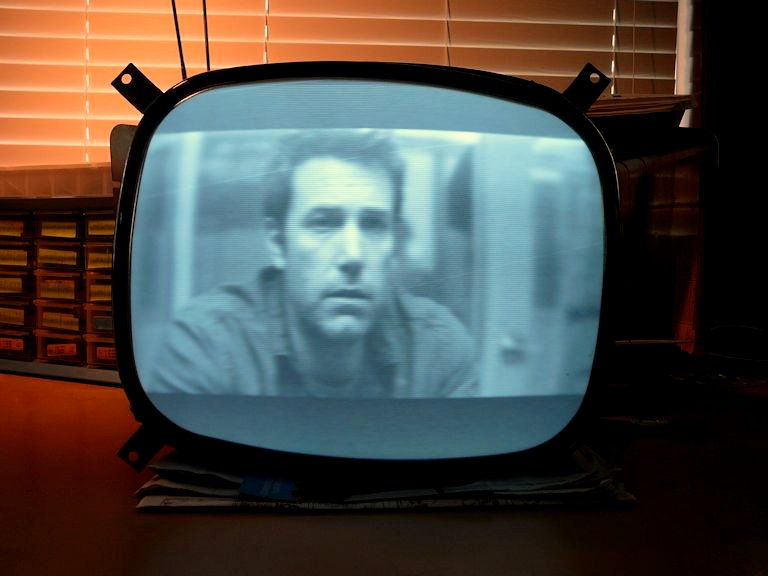
My camera makes black and white screens look too blue, so in this final photo,
I converted the screen area to greyscale, to give a more accurate portrayal of
what the TV looks like in person. The second photo shows my first 14-S-7070G.
I usually avoid repeating projects, but it was fun to revisit this TV
so many years later. The project went smoothly, not only because I
knew what to expect, but also because in most cases I used newer types of film capacitors
that are less bulky than orange drops. The smaller replacements minimize under-chassis crowding and
blend well visually.
In hindsight, this model wasn't an ideal choice for a first TV project. The
electronics are standard for that era, but the cramped location of many components
doesn't make it easy to service. Since that early effort, I have restored many TVs that were
easier to manage.
With a bright, sharp picture, this TV is a pleasure to watch. I don't know if I'll keep it
one forever—space is hard to come by in this house, even after I built a dedicated
TV/Radio display room—but I am definitely
enjoying it in the meantime.
|