RCA Rider Chanalyst 162-C Test Instrument (1940)


The RCA Rider Chanalyst is a fascinating device. Introduced in the late 1930s, it's
an attempt to provide an all-purpose instrument for the radio repairman.
It's also a beautiful piece of equipment, for those interested in such things.
Description
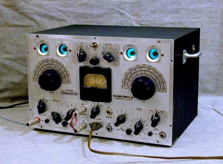
Considering all the things it's designed to do, the Chanalyst comes in a pretty
compact package, measuring about 14 x 10 x 9 inches.
The first photo shows it in operation.
The front panel is made of chrome-plated brass. The cabinet body is
wrinkle-painted steel, with brushed-steel handles on each side.
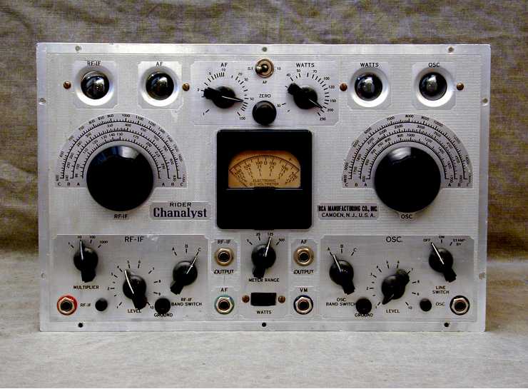
The second photo shows the front panel and controls a little more clearly.
The Chanalyst is unusual in having four green magic eye tubes,
which are used as indicators for the instrument's various "channels" (hence,
the name, which combines the terms channel and analyst).
A fifth indicator is the DC voltmeter in the center of the panel. The meter's
zero setting is in the middle of the face, allowing it to
indicate both negative and positive voltages
When I got my Chanalyst, I told my son that the front reminded me of two faces,
one on each side, with two eyes apiece. He replied that he saw three faces—and
the middle one looked a little crabby!
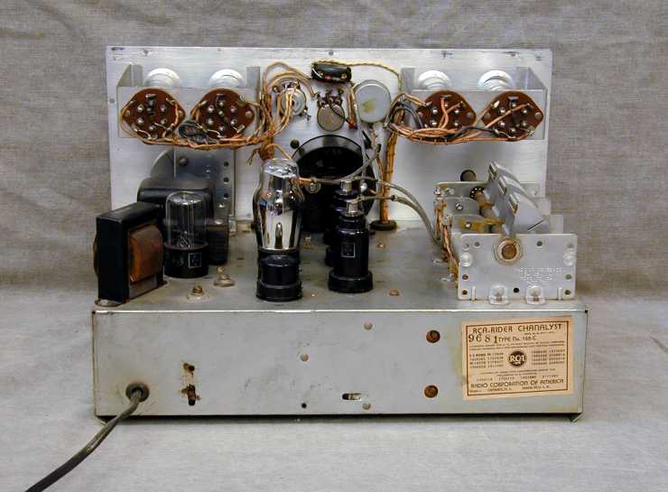
Here's a look at the back of the chassis.
Most of the goodies are hidden underneath the chassis, of course. The construction quality
of this instrument is quite high. The RF section, for instance, is shielded in a cage
made of solid copper.
When I got my Chanalyst, the previous owner had already replaced the electrolytic capacitors
and cleaned the controls. Before using it for any serious work, I'll need to
replace some more capacitors and go through the factory calibration process.
The paint on the cabinet body was scuffed in a few places, so I cleaned it up and gave it
a couple of light coats of Krylon paint. The original factory color was not quite this dark,
but I think the black looks good (and that's what I happened to have on hand).
The Chanalyst went through a few versions, A, B, and C. Mine is a C, the latest version.
Among other things, the C version moved a couple of output jacks from the rear of the
cabinet to the front panel.
The Chanalyst was supplied with four cables: RF-IF, Oscillator, AF, and Voltmeter.
Each cable's probe has a resistor or capacitor to properly couple the
signals and the color of the probes is matched to colored washers on the
corresponding jacks. A fifth interchange cable allows you to connect two channels for various operations.
Operation
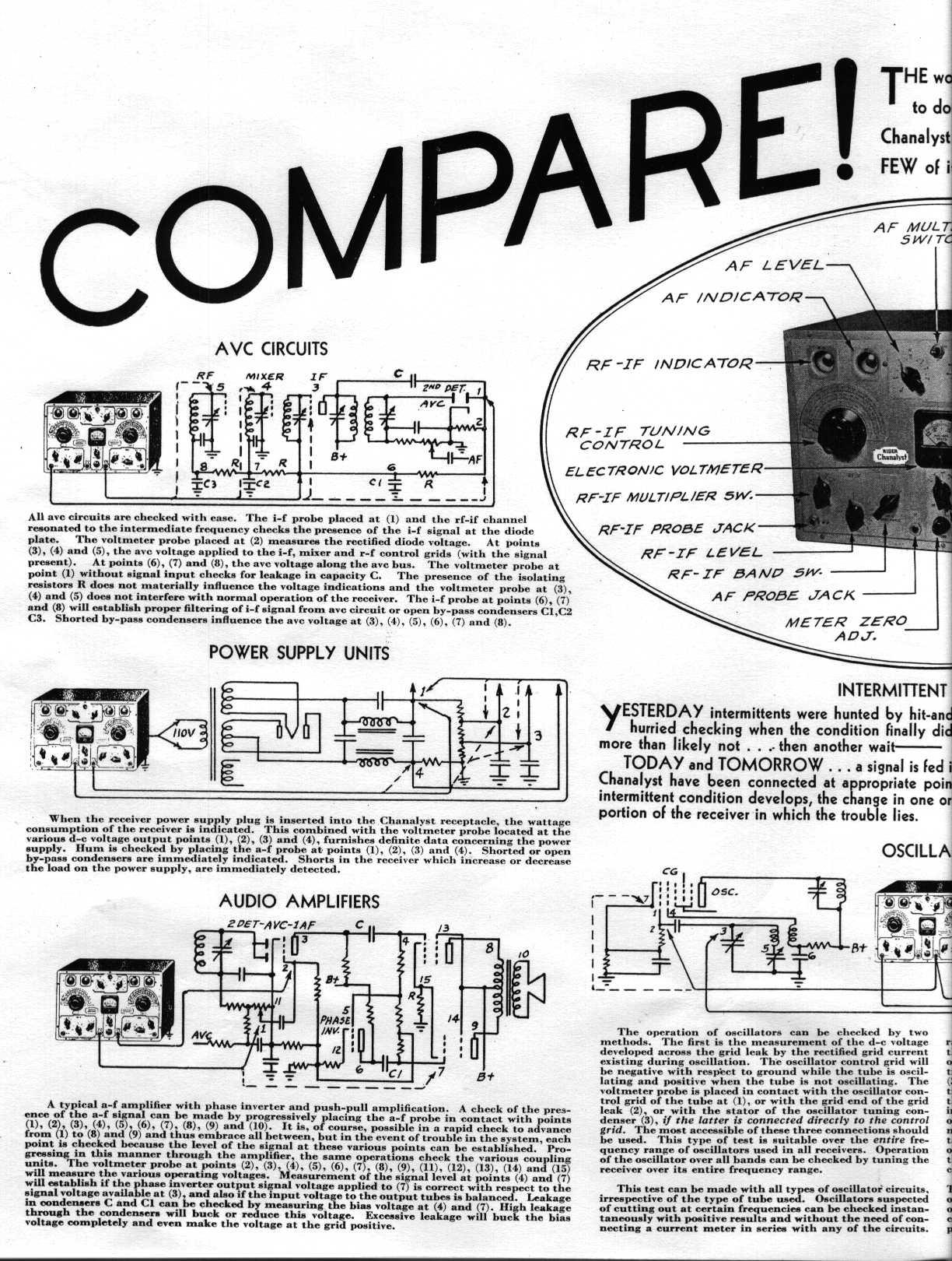
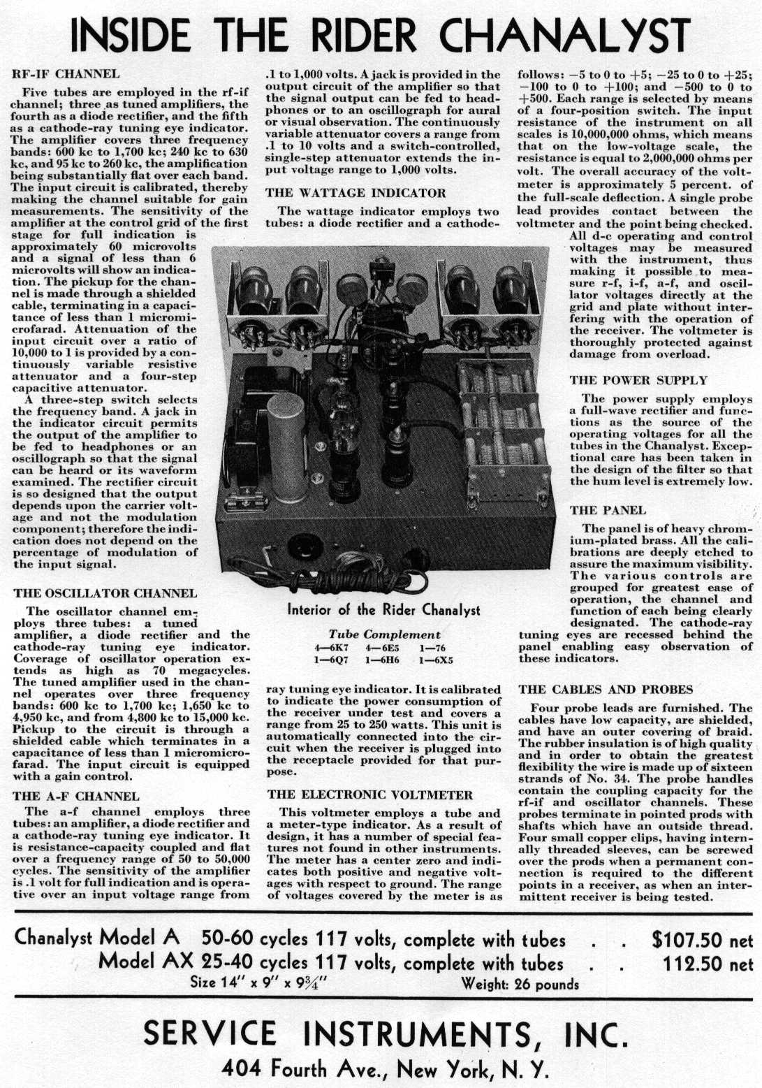
Rather than paraphrase, let's read about the Chanalyst's operation in the words
of its designer, John F. Rider, a noted engineer of the time and publisher of
the famed Rider schematic series, as well as many articles and books. Below
are the pages of an early brochure describing the Chanalyst.
Whew! That's a lot to absorb in one sitting. If you're thinking there's still more
to say, you're correct. The owner's manual for the 162-C is over 50 pages long.
If you don't mind downloading a 15.5-megabyte PDF file, you can get it at this URL
on the BAMA ftp site:
ftp://bama.sbc.edu/downloads/rca/162c/
Note the price in the brochure, by the way. In the 1930s, $107.50 was a fair chunk of change!
Operating The Chanalyst as a Radio
Those familiar with radio design may have noted that the Chanlayst's channels comprise
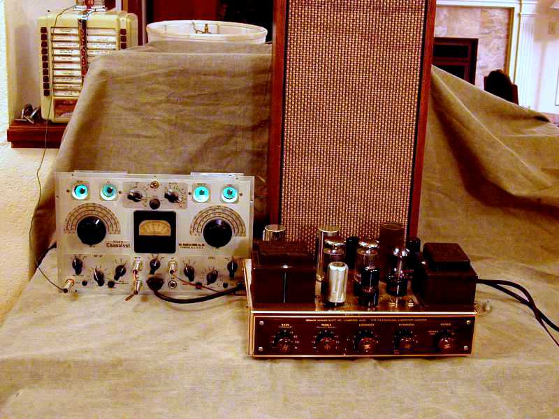
the sections of a basic receiver. Using three cables, you can hook up the Chanalyst to perform
as a TRF (tuned regenerative frequency) radio. This photo shows how.
At lower left, you'll see a plug in the RF-IF input jack. This is connected to a
long wire which acts as an antenna. Near the middle, under and just to the left of the
voltmeter, is a short interchange cable, which connects the RF-IF output jack to the
AF input jack. To the right of that is a third cable, connecting the AF output to
my Scott 210-B monophonic audio amplifier, which in turn
connects to a speaker. (If you own an earlier mode, the RF-IF and AF
output jacks may be located on the back of the cabinet.)
The big knob on the left is used to tune in the desired station, and the
rest is not hard to figure out. The Chanalyst provides a power plug in the
front for wattage tests, so I plugged the amplifier in there. If you don't
have an amplifier, you can plug a pair of headphones into the AF output jack.
Pretty fun! My Chanalyst worked pretty well as a radio, indicating that its health
is basically good. I will finish the remaining restoration work before I use it a lot,
however.
|