Philco Model F4626M "Miss America" Television (1958)


I bought this Philco F4626M "Miss America" television as a Valentine's Day
present for my wife in 2011. It will look great alongside her favorite
Mid-Century Modern things.
Philco and Miss America
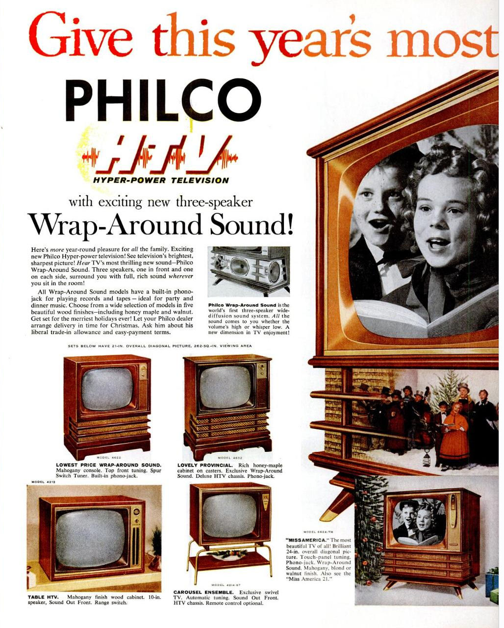
Philco had a close relationship with the Miss America Pageant during the 1950s. Its
top-of-the-line TVs used the Miss America name and Philco spent heavily on
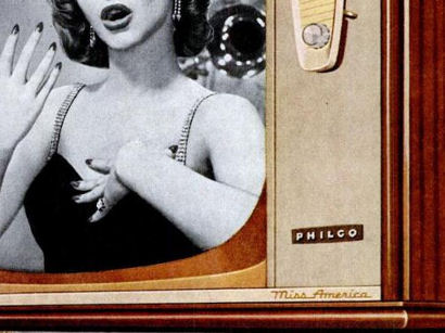
advertising. In this full-page ad from Life Magazine, the
newly elected Miss America, Marilyn Van Derbur, costumed in gown and tiara, introduces
the new 1958 Miss America television.
The sponsor relationship was mutually beneficial. Miss America appeared in glossy
national advertising and promotional events around the country, at Philco's
expense, and the Miss America image lent a glamorous aura to
Philco's priciest models.
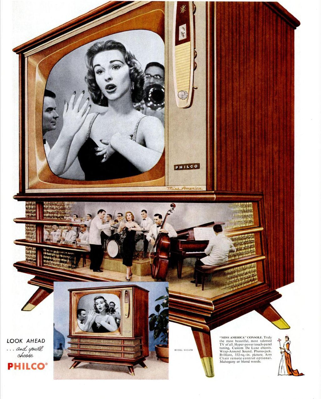
The previous ad described the new Miss America TV as a "Hyper-power" set
with Wrap-Around Sound. The next one shows our TV in a full-color, two-page spread.
It extends the Hyper-Power idea to the chassis and tuner as well as the triple speakers.
"Arm Chair" remote control was available as an option. I love the
miniature orchestra inside the speaker compartment!

In this 1958 Philco ad with a Christmas theme, the miniature
orchestra has been replaced with a group of carolers:

There is no single Miss America television. It is a series name, like Coupe de Ville,
given to high-end models over a span of years.
The Philco line included a number of cabinet styles, colors, and features.
Less expensive consoles also had triple speakers and wrap-around grilles,
but the Miss America name was reserved for the top of the lineup.
Look for Miss America in script at the bottom of the control
panel.
My wife's TV is a "Miss America 21" with a 21-inch screen. The most expensive Miss
America model for 1958 added remote control and an even bigger 24-inch screen.
Finding Miss America
Late one Saturday night, I was idly scanning Craigslist ads and I noticed one for this
television. I emailed the owner immediately and drove the set home the next afternoon.
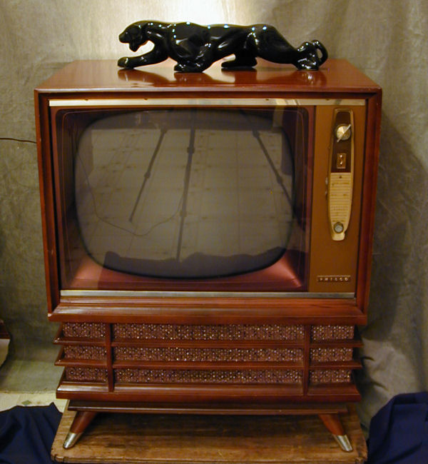
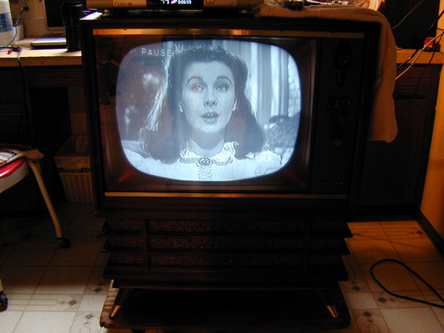
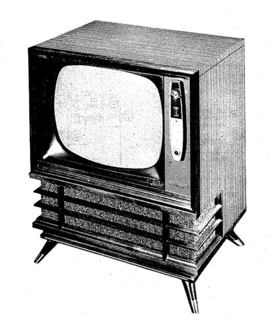
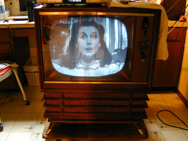
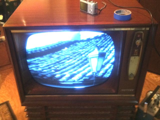
Its electronic condition was unknown but the outside was almost like new, as you
can see from this snapshot, which I took right after unloading it. (The dark lines
on the screen are reflections of my camera tripod legs.)
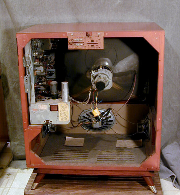
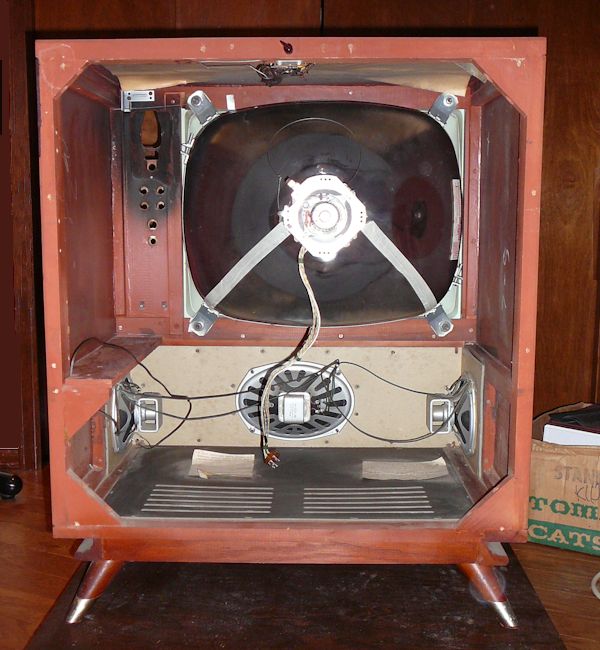
This TV still has its back cover. A look inside shows an unmolested chassis and
surprisingly little dust. In the bottom are the three generous speakers for
"Wrap-Around Sound." The little yellow can hanging from the base of the
picture tube is a CRT brightener, a sign that the tube is weak.

There are no signs that this TV was ever serviced, apart from replacing a few tubes and
plugging in a brightener.
Miss America Electronic Design
The model number on this TV's back cover is F4626M. Here's the image from
the Sams Photofact:

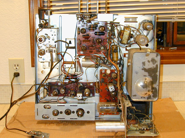
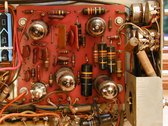
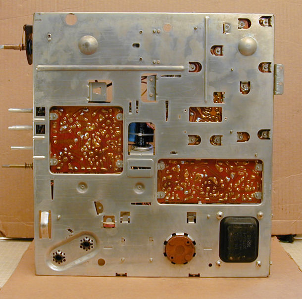
The chassis (8L71) is a conventional late-1950s TV design with three printed
circuit boards for the audio, video, and sweep sections. The electronic layout
is spacious and easy to service.
The Miss America television uses 18 tubes.
| Tube |
Type |
Function |
| V1 |
6DE6 |
1st Video IF Amplifier |
| V2 |
6DE6 |
2nd Video IF Amplifier |
| V3 |
6AM8 |
3rd Video IF / Video Detector |
| V4 |
6U8 |
Video Amplifier / Noise Inverter |
| V5 |
6AQ5 |
Video Output |
| V6 |
6BY8 |
Audio IF / Limiter |
| V7 |
6AL5 |
Discriminator |
| V8 |
6AV6 |
AF Amplifier / AGC Clamper |
| V9 |
6AQ5 |
Audio Output |
| V10 |
12BR7 |
Sync. Separator / Horiz. AFC |
| V11 |
12AU7A |
Vertical Multiplier |
| V12 |
6CM6 |
Vertical Output |
| V13 |
12AU7A |
Horizontal Multiplier |
| V14 |
6DQ6GTA |
Horizontal Output |
| V15 |
6AX4GT |
Damper |
| V16 |
1B3GT |
High Voltage Rectifier |
| V17 |
5U4GB |
Low Voltage Rectifier |
| V18 |
21BSP4 |
Picture |
The service manual is Sams
Photofact Set 403, Folder 2.
You can get a copy directly from Sams or from various other sources. This article uses the part numbers given
in Sams.
Philco marketed essentially the same chassis in many flavors.
This Photofact lists over 20 different models, including
various cabinets and optional features such as UHF tuning,
remote control, and two sizes of CRT.
Replacing Power-Supply Capacitors
Before trying to power up the TV, I'll replace the electrolytic capacitors.
This will prevent unpleasant surprises such as burning up the
power transformer if a filter cap has a short circuit.
The television's eight electrolytics are contained in two metal cans labeled
C1 and C2. I'll use a different technique for each can to match their
different situations. You can read more about capacitor replacement in
Replacing Capacitors in Old Radios and TVs.
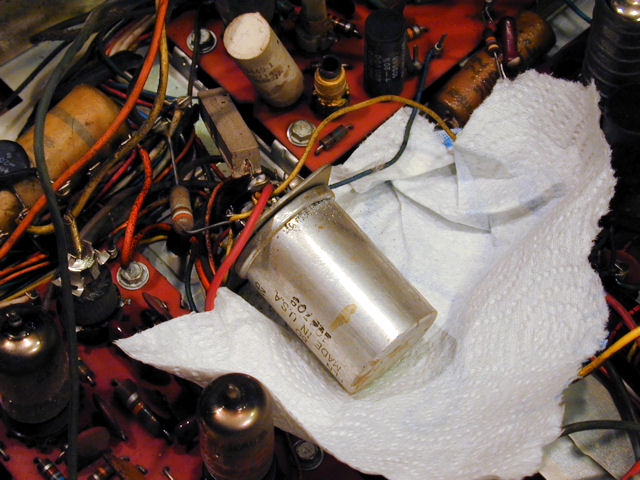
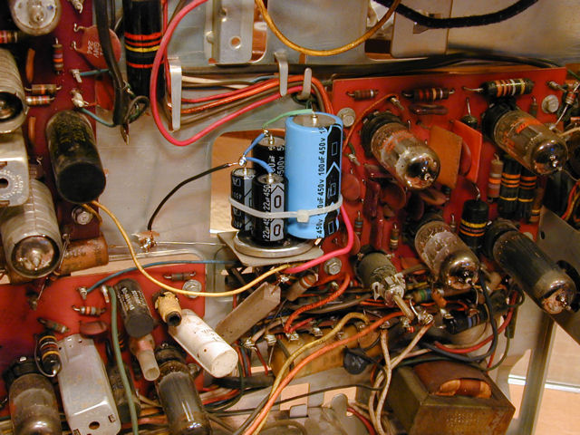
Mounting Electrolytic Capacitors on a Terminal Strip
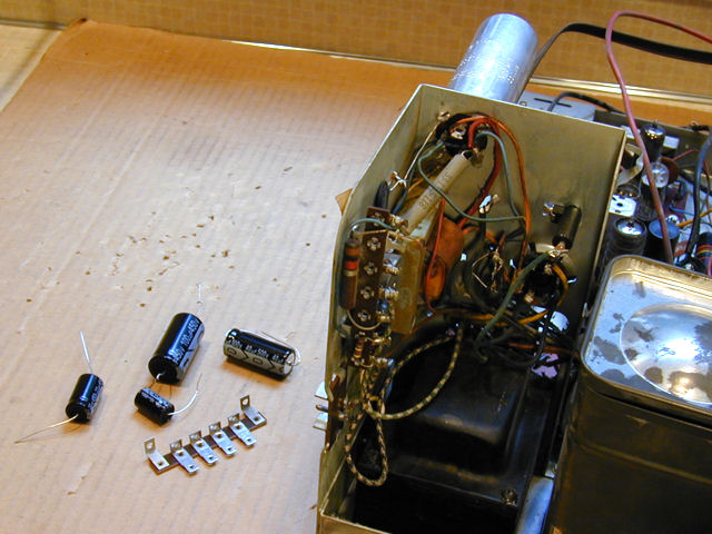
The next photo shows C1, the tall aluminum can near the
upper right. Although I often "restuff" old cans by hiding new
caps inside, that's not practical here because the can is too small
to hold all four replacements. There's ample room to mount new
capacitors under the power subchassis, so that's where they'll go.
On the workbench you can see the four new caps and the terminal
strip that I'll use to mount them.

This terminal strip fits the space neatly.

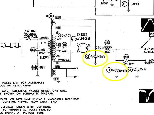
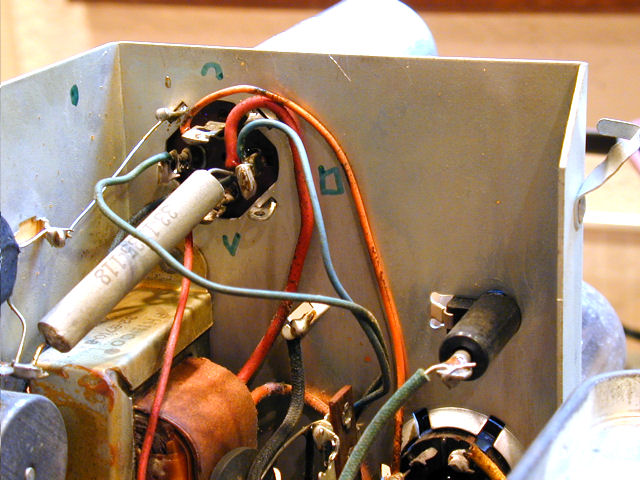
The four capacitors in the C1 can are identified with geometric symbols
in the schematic, on the can's exterior, and in the phenolic base where
the can's terminals are mounted. Capacitor C1A (40 mfd) is marked with
a semicircle; C1B (100 mfd) is marked with a square, and so on. This snippet
of the schematic shows C1A and C1B, which act as power-supply filters.

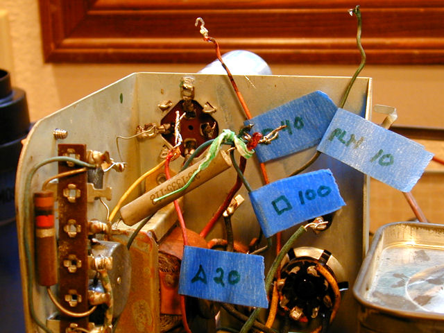
I'll be disconnecting all of the capacitor leads from the can and soldering them
to the new caps. To keep everything straight, I drew each capacitor's symbol near
its terminal on the chassis.

I also labeled the leads before unsoldering them. C1B connects to
three wires and a resistor and I used a twist tie to temporarily hold those
leads together.

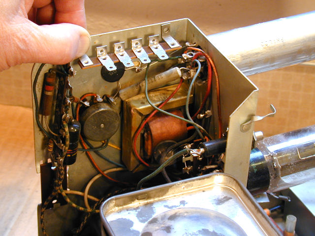
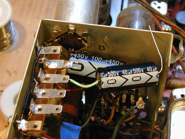
In the next photo, we're partly done. I drilled one hole in the chassis to hold
the terminal strip with a screw. Two screws aren't really necessary for this light assembly
and I have already soldered my new ground wire directly to a chassis lug, so we're
not depending on screws to make ground connections.

The positive lead of capacitor C1B (100 mfd) has been soldered to the first terminal.
(Notice the stripes of minus signs and arrows that point to the negative leads on
these modern electrolytic capacitors.)
It doesn't matter what order I use for the caps on this terminal strip,
as long as I wire them correctly. I installed C1B innermost because it's
large and I wanted it more out of the way.
In the previous photo, I temporarily laid the second capacitor (C1A) on its terminal to
show the insulation on its positive lead. I'll solder it from the
other side of the lug and then bend the lead to position the cap body slightly behind
the terminal strip. Insulation on that hidden hot lead will help prevent short
circuits if a future repairman pokes around in there.
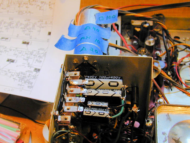
In the next photo, the C1 replacement is complete. All four capacitors are installed on the
terminal strip, which is screwed to the chassis. They share a common
negative connection to chassis ground.

After I finish more immediate tasks, perhaps I'll add some kind of insulating
strip or plate over those positive terminal lugs, which carry high voltage. Lots
of other points on the chassis carry high voltage, too, but these are in a
location where it would be easy to brush them accidentally.
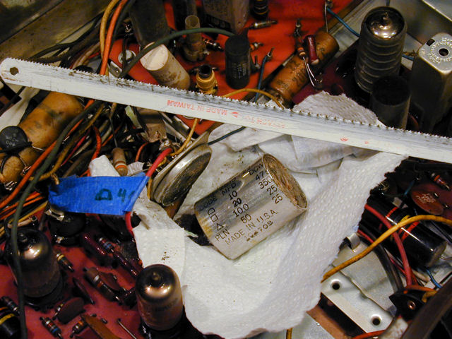
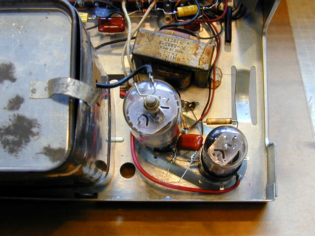
Mounting Electrolytic Capacitors on a Can Base
The other four electrolytics are contained a stubby second can named C2.
It has geometric value markings, too, although they're tricky to spot.

It's impossible to fit four electrolytics in this can and there isn't a lot
of space for a terminal strip, so I'll saw off the can and mount the
electrolytics on its base. A major advantage of this method is that I won't
need to disturb any of the original wires. Instead, I'll drill tiny holes
in the base and wire the new cap leads directly to the old terminals.
The can is soft aluminum and the contents are
even softer, so I can easily do this with a hacksaw blade held in my fingers.
A paper towel catches most of the waste material. After the can is decapitated,
I'll carefully clean up using a small brush and vacuum.


I sawed the can right above its lower lip to retain the rubbery insulation
gasket in the base. Below you can see the intact base. Notice the four metal terminal
ends visible within the black rubber gasket. I'll drill little holes next
to each terminal and snake the new capacitor leads down to the terminals underneath,
where they'll be easy to solder on.

Incidentally, this rubbery gasket is responsible for the capacitor's failure over time.
It's intended to keep the capacitor's electrolytic paste moist, and it worked during the
natural service life of this TV.
At the microscopic level, however, its seal is far from perfect. Over the decades,
air and water molecules can pass through the seal pretty freely, eventually drying out the paste and
turning the capacitors into garbage. This degradation happens no matter how the
TV was stored or whether it was even used. If you found a NOS (new old stock) 1958
capacitor in its original package, it would likely be as bad as the one we're replacing.
Before soldering anything, let's try out the new caps in this space and make
sure we know which capacitor belongs to which terminal. Although I didn't label the old
wires (which won't be moved anywhere), I did take a moment to read the schematic and
trace connections with an ohmmeter to confirm that I had correctly identified each terminal.

Just as with the previous can, I'll put a short piece of insulation on each
cap's positive lead. I'll also leave about 1/4 inch of extra length on each lead
so that the caps will stand slightly above the case rather than rest on it.
The possibility of short circuits is remote if I wire everything correctly,
but the metal lip on the base is still connected to chassis ground and I
don't want any part of the new caps to touch it directly.
Here's the finished capacitor assembly, secured with a nylon zip tie. The four
new electrolytics share a common connection to chassis ground.

As mentioned earlier, there are cases when I restuff old capacitor cases and
make other efforts to preserve the original appearance of a chassis. In this case,
while I'm concerned about the cabinet's cosmetic appearance, my goal
with the electronics is to make them functional and reliable. My wife won't
give a hoot what the innards look like, as long as it has a great picture and great
sound.
In my RCA CTC-7 color television
article, you can read about how I used the same method but replaced the
old cans. That early color set is worth more than this Philco and has greater historical
significance, so I went the extra mile.
First Power-Up
Now that I have replaced all of the electrolytic capacitors, it should be comparatively
safe to power up the television for the first time. No doubt it still has a number of
problems, but this will give me a baseline idea what shape it's in.
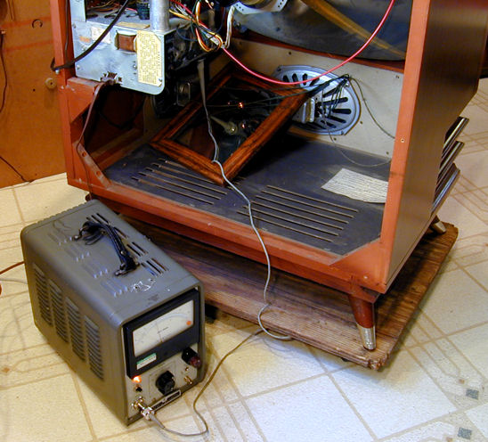
For this initial trial, I'll use a variac to slowly increase the line voltage and
keep a close eye on the TV's power consumption with an ammeter. A metered
variac is ideal for this purpose. If your variac lacks a meter, you can plug
it into a handy device named Kill-A-Watt, which lets you monitor
either amps or watts; it's available at many hardware and home improvement
stores for about $30.
The first trial was encouraging. I got normal audio and a raster (lighted area)
on the screen with full horizontal deflection. The vertical height was only about half
size, however, with a bright horizontal line at the bottom. Clearly, among the many
paper and molded paper caps remaining in this TV, those in the vertical
deflection circuit are especially bad.
There's no point in playing a TV at length in this condition, so I powered
down and resumed recapping.
Replacing Capacitors on Printed Circuit Boards
Nearly all of the remaining capacitors in this TV are found on printed
circuit boards. In some TVs such as my Philco
Predicta, the underside of the circuit board
is not easily reached, and so it's reasonable to replace a cap by
snipping the original leads and soldering on a new cap with a "J hook"
or "pigtail" connection.
These boards are accessible, however, so I'll use a tidier
method: removing the old caps completely and installing the
new capacitor leads through the original holes in the PC board.
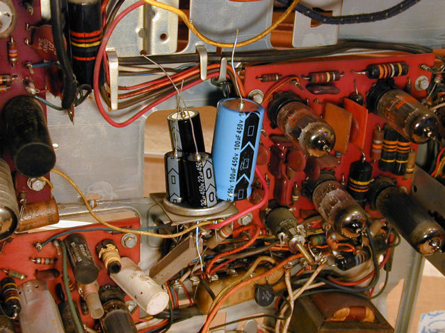
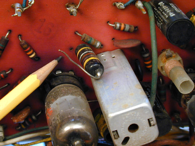
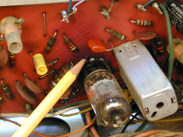
In the following photo,
I already have installed one new cap, the yellow cylindrical one. To its right, also
standing vertically on the board, is a striped "bumblebee" cap that
I'll replace momentarily. (The
capacitor replacement article mentioned earlier has
photos and descriptions of vintage capacitor types.)

Unsoldering the old part requires locating its leads on the underside
("foil side") of the
PC board. Sometimes the service manual includes photographs of the board
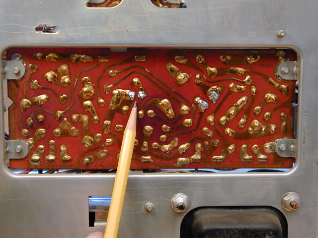
undersides, but the Sams Photofact for this TV does not. If you shine a strong light
on the opposite side of the board, as shown below, you can quickly locate the
trace where each lead is located. Notice how this bumblebee cap's bare lead is in a little
upward-facing peninsula, below a pair of thin traces with a broad upside-down V shape.

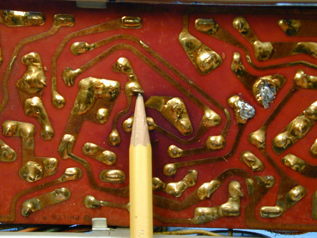
On the opposite side of the board, we see the same pattern in reverse: our peninsula
lies below the broadly angled pair of thin traces. The pointer touches the lead that
we're going to remove. See how the lead's end was bent in a little "L"
shape to make better contact with the foil trace.

I'll heat that connection with a soldering iron and then remove the lead.
You can remove the old lead from the top or bottom of the board. If the lead is
readily accessible from the top, you can snip it up there, heat the connection,
and then push the snipped end downward through the board with a toothpick
(solder doesn't stick to wood).
If the lead can't be reached from above, you can heat the connection below and
then pull on the component to draw the old lead up through the board.
If melted solder covers the hole after the lead is withdrawn, reheat the joint and
twirl a toothpick in the hole to clear it.
Here is the old snipped lead, free above the board. Its hole is empty of
solder and ready for a new lead.

When working on PC boards, work quickly and use only as much heat as needed to flow the solder.
The foil traces are delicate and you don't want to loosen them from the board.
You also can use a little tool called a solder sucker to remove excess solder when first heating the joint.
I use suckers occasionally if the old joint was slopped with excessive amounts of solder.
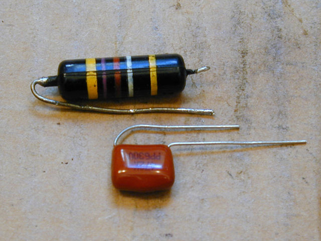
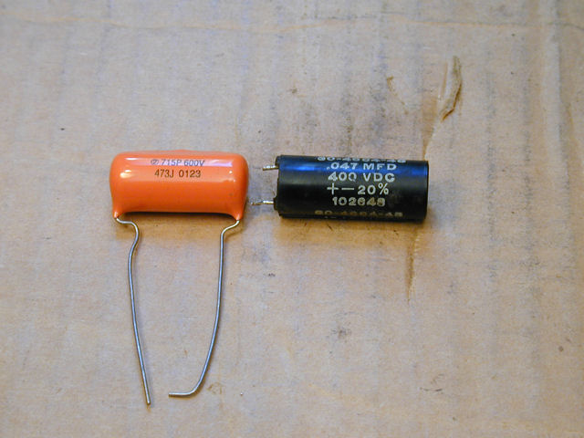
Here's the new dipped-mylar cap that will replace the old plastic-coated bumblebee:

After trimming the new cap's leads to length and inserting it, I bent each end
on the foil side with a tiny L shape and then soldered it in place. The L isn't
absolutely essential, but it provides a little stronger physical connection.
These photos show the capacitor installation from both sides of the board:


The following photo shows a type of molded paper capacitor that I hadn't seen before. Unlike
the striped bumblebee that we just saw, this one is clearly designed for PC board
installation: a flat-bottomed cylinder with short radial leads. Despite the different skin,
its internal condition has degraded as much as the other caps, so away it goes!


Once you have replaced a few caps on this type of board, you'll find that it goes
more quickly than replacing capacitors wired point-to-point.
First Picture
Since Miss America's most obvious blemish was in the vertical sweep circuit, an early
priority was to recap the sweep board. Here's that board before and after recapping:


Not surprisingly, the new caps cured the vertical problem and produced a decent
picture for the first time. (In the second photo, I turned down the lights to
reduce glare from the TV's safety glass.)

The image is far from perfect. I already knew the picture tube was weak, so
naturally it doesn't have great brightness or contrast. I can't get
the vertical linearity quite right and the horizontal hold is rather unstable.
Nonetheless, this ain't bad for early days.
Recapping is Finished!
Finishing the other boards was simply more of the same.
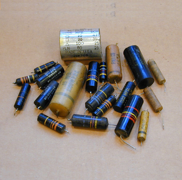
Here's a view of the recapped chassis from above and below, and most of the caps that
came out of it. Still in the chassis are the four electrolytics inside can C1, which
I left in place (although electrically disconnected) for appearance's sake.


The TV also contains a number of ceramic disc caps, but those are so reliable that I won't replace one
unless it obviously has failed. Those caps are chiefly found in tuned RF and IF circuits
that would probably need to be realigned if I "shotgunned" all of those
components.
This TV has a few "couplates," an early form of integrated circuit
that typically contains a capacitor or two plus a few resistors. These are roughly
midway in the reliability scale: not as awful as paper capacitors but not as
bulletproof as ceramic discs. Although I replaced one couplate in my
Predicta, I'll leave these alone until I see how the TV works.
Improving the Vertical Linearity
At this stage, I wasn't able to attain correct vertical linearity
no matter how I adjusted the height and linearity controls. Here are
two photos that illustrate the problem.
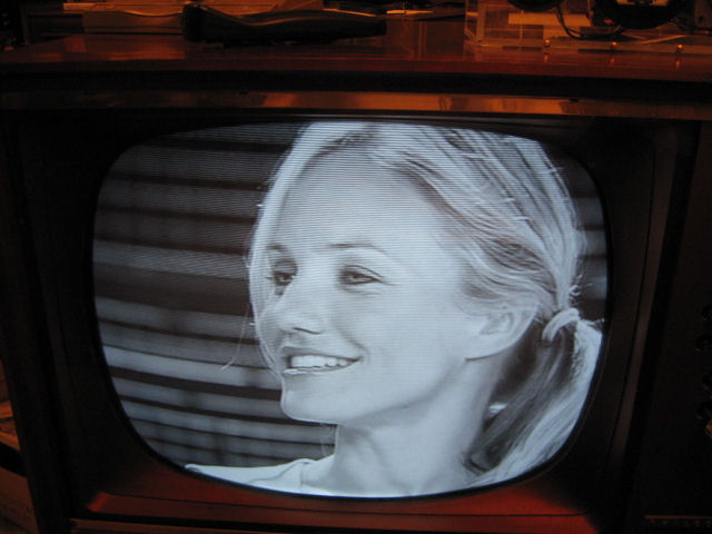
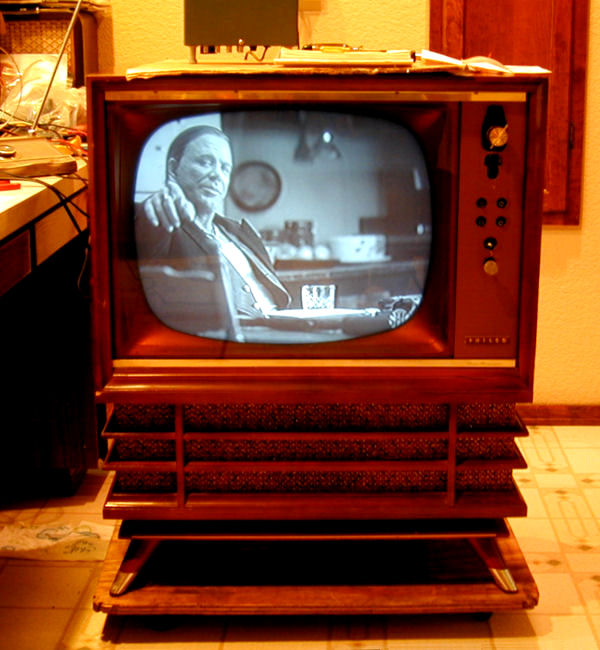
In the first photo, a medium close-up from a live broadcast, most viewers wouldn't
notice any deformation.

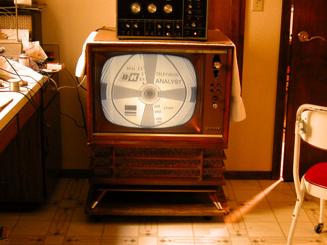
Displaying a test pattern tells a different story. See how the top half of the
screen is vertically stretched, compared to the lower half. Instead of a regular
circle, we have an egg with a slightly elongated top.

It's rare to find a vintage TV that doesn't have linearity issues. I have already
replaced the caps in this circuit and confirmed that the tubes are good. Resistors
are logically the next things to check.
Most carbon resistors drift somewhat in value (usually upward) over a few decades. In some
circuits, the difference doesn't matter because the precise value wasn't critical in
the first place. In a 1950s TV, many resistors originally had a
20% tolerance, meaning that the actual value could be 20% higher or lower than the
specified value without affecting performance. In some circuits, a resistor can
be even farther off value without causing problems.
The vertical and horizontal sweep circuits, however, demand precise timing, and thus
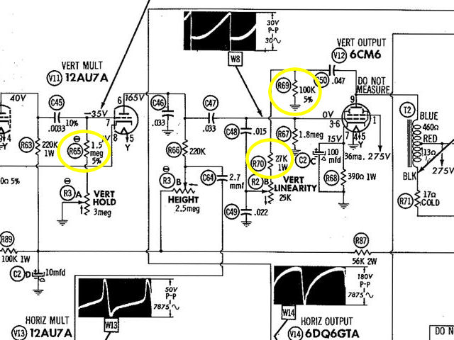
some of their resistors must have a more exact value. Reviewing the schematic,
two resistors (R69 and R70) are obvious candidates for checking because they lie
between the vertical linearity control (R2B) and the plate of the
vertical output tube (V12).

Notice that R69 has 5% tolerance; its value should be more precise than usual. Another
resistor in the neighborhood, R65, also has 5% tolerance. It's located on the input grid
of the vertical multiplier tube (V11), whose output controls vertical height as well
as linearity. Replacing those three resistors noticeably improved the linearity.

After I adjusted the width and centering, the TV seemed almost ready for prime time.
Flyback Troubles
When I played the set in a cabinet for a longer period, however, trouble reared
its head. I heard a sudden loud sizzle and the picture went
crazy, darkening and dissolving in a blizzard of bright horizontal streaks.
I quickly powered down, opened the high voltage cage, and turned the set back on,
with my hand hovering over the power switch. As soon as the HV spooled up, I
saw a fat, continuous blue spark shoot from the flyback to the side of the
metal cage. Turn off the juice!
Flyback trouble is ominous because flyback transformers are not readily
interchangeable and replacements are sometimes hard to find.
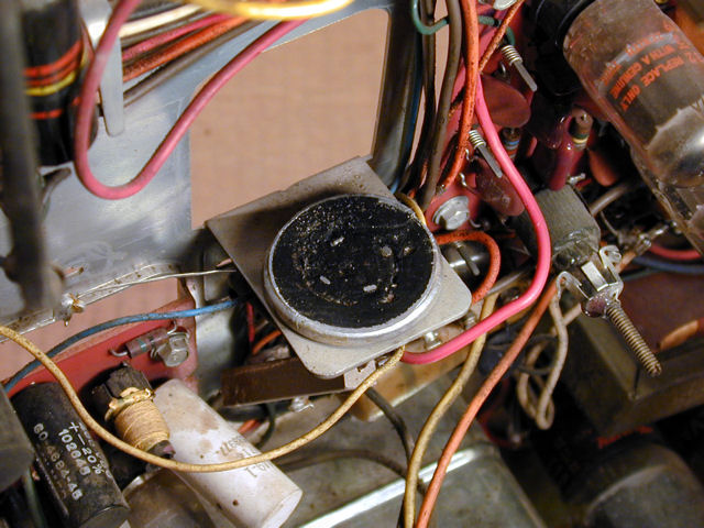
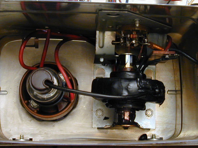
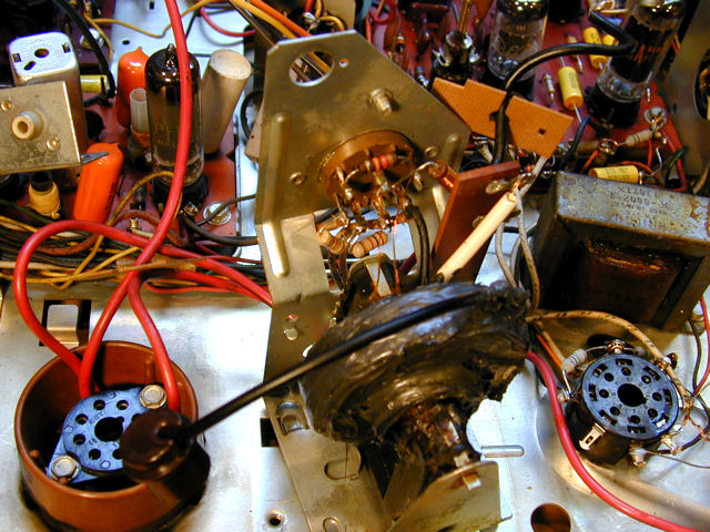
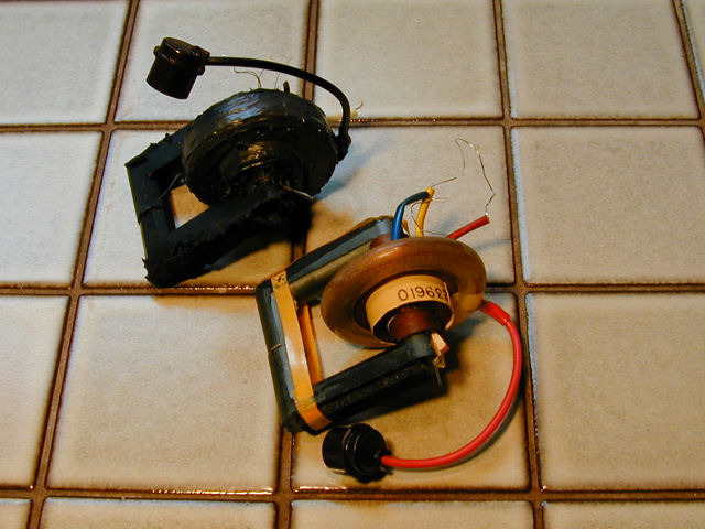
When I first inspected the set, I had noticed a few little drops of melted
wax under the flyback. Here's a view inside the HV cage earlier in the
project.

To the left is the 1B3GT rectifier tube. On the right is the flyback,
whose doughnut-shaped coil is insulated with black wax. I have seen
worse-looking flybacks than this which still performed reliably,
so I wasn't alarmed by the appearance.
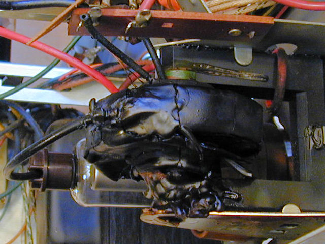
Here's how the flyback looked after the sizzling incident. The
coating has cracked and the amount of newly melted wax shows that
it seriously overheated. At the very least, the insulator must be
replaced.
I had heard of recoating flybacks with RTV sealant, but never tried it myself.
Why not treat catastrophe as an opportunity? I picked up some RTV at an auto
parts store.
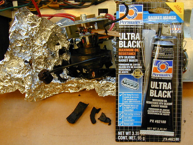
Reinsulating the Flyback Transformer
Before applying sealant, you'll want to
remove the old wax and inspect the coil. In the following photo, I have started flaking
off some loose wax layers. I put the RTV in the photo to show
what type I used (the black "sensor safe" stuff).

I removed the flyback mounting screws so that I could turn the assembly from side to
side somewhat without having to unsolder all of its connections. Some of the
flyback leads are delicate, as we'll see later.
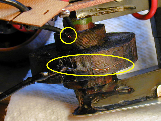
In the next photo, the bulk of the wax is gone. When I warmed the doughnut with
a heat gun, the wax loosened and came off easily in pieces. Melting
it entirely down to liquid would take longer and make a real mess.

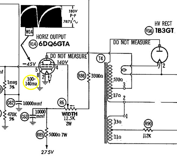
Two interesting spots are highlighted in yellow. The circle shows where
the lead from the 6DQ6GT output tube enters the coil (labeled terminal
3 in the following schematic). The yellow oval shows where a
lead exits the coil and connects to the 1B3GT rectifier.
Before applying the RTV, I cleaned the coil with a mild solvent and let it
dry thoroughly. Then I covered the entire doughnut and gave it 24 hours to cure.

Repairing the Flyback Lead
After I had reinsulated the flyback, a VideoKarma forum
member suggested a simple test: checking for continuity
between the plate of the 6DQ6 horizontal output tube and the plate of
the 1B3GT rectifier. Notice in the schematic that this path leads through
the flyback (T4); the resistance for that part of the transformer is given as 530 ohms.

To my dismay, the ohmmeter showed no continuity between those points. This suggests
that the flyback short-circuited, overheated, and then fried somewhere inside.
The coil interior is a mass of hair-thin wires wound in precise, complex
patterns. If a meltdown happens deep inside, the damage will be irreparable.
Although I had found no continuity at the tube caps, I tried checking the leads
where they actually entered the coil, just in case one was funky. There, I spotted something
intriguing.
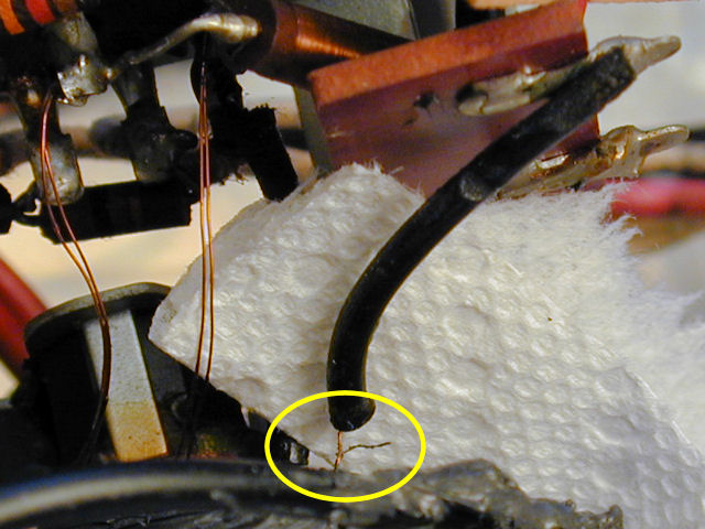
As you can see in the next photo, wires from the coil to its terminals
are in pairs, and one wire to the 6DG6GT output tube
is broken! I hadn't noticed it earlier because the stub had been contained
in the insulating tube; it only emerged when I gently nudged things around.

Thin coil wires are covered with clear insulation. I carefully scraped the tiny
broken end and tried again with my ohmmeter. From that stub to the
1B3GT rectifier lead, I found continuity and measured 541 ohms. That's within
a few percent of the 530 ohms stated in the schematic, suggesting that
the coil interior has not massively shorted. If I can reconnect this lead, perhaps
the flyback can be saved!
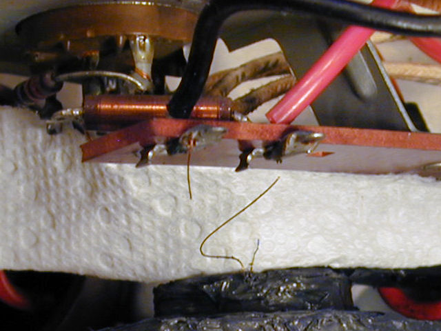
In the following view, I have cut that lead midway and removed its insulation.
You can see that one wire was still intact. The remainder of the
little stub was completely missing, however. Could it have vaporized when the
severe arcing occurred?

I was honestly not optimistic about repairing the flyback. It's difficult to
manipulate and solder such thin wires in a cramped space. And, even if that
repair were successful, there was no guarantee that the flyback didn't
have other, unrepairable, damage farther inside where no soldering iron
can reach. (There are instruments for testing flybacks, but I don't own one.)
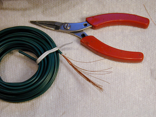
If the flyback was truly fried, I had nothing to lose by trying. I stripped the insulation
from a length of multi-stranded wire and harvested two strands to use as
new leads.

Using care, I soldered extensions onto the tiny stub and the longer wire that I
had cut, slipped a length of insulation over them, soldered them to the rectifier
terminal, and then applied a lick of RTV at the spot where they exit the flyback coil.

My repaired flyback won't win any beauty contests, but I'll jump for joy if
this repair succeeds.
Testing the Repaired Flyback
I put everything back together and cautiously powered up the TV in a darkened
room, watching the flyback for any signs of arcing. No sparks appeared, and
the TV's sound and picture looked normal. When I put a listening tube
inside the HV cage, however, I thought I heard some very faint ticking
or sizzling sounds from the coil. Looking very closely at the screen,
there also appeared to be very short dashed lines zipping across from
time to time.
Meanwhile, I discovered that
Moyer Electronics had
a replacement flyback in stock, so I ordered one. Given the giant
arc and the mudslide of melted wax that I'd seen before, I had little
confidence that my patched-up flyback would hold up. After another
five-minute trial, I called it a night.
The next day, I decided to play the TV for a while, to
see what would happen. Since a replacement was on the way, it
wouldn't be a huge loss if my old flyback went up in smoke.
I turned on the TV and sat next to it, watching intently for any sign of
trouble, That got boring after a while, so I checked the voltages on the
grids (pins 4 and 5) of the 6DG6GT output tube and was reassured to find them normal.
I wheeled the TV into the office next to my desk, where I could keep an eye on it,
and just let it play. No sizzling sounds, no little dashes on the screen, just
a nice picture and great audio.

Several hours later, I turned it off, thinking that maybe the repair had worked,
after all. Will this flyback last indefinitely? Hard to say, but I have a new one
in case it fails.

Improving Vertical Linearity
I wasn't satisfied with the vertical linearity, even though I had replaced
all of the capacitors and many of the resistors in that area. Lacking any other
ideas, I ordered a new 6CM6 tube and gave that a whirl. Between the new tube
and playing around some more with height and vertical position, I finally got
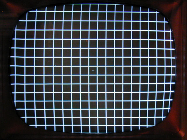
reasonable linearity.

In the photo, there are the same number of rows above and below the center dot,
and the squares at top and bottom are very nearly the same height. The horizontal
linearity isn't perfect, but this TV has no adjuster for that and I'm not
going to start changing component values in hopes of improving it. On some TVs,
you simply have to accept some little imperfection or another.
Rejuvenating the Picture Tube
After using the TV for a while, I decided to try my Sencore CR70's auto restore
function on the CRT. Although the picture was passable with the CRT brightener,
I discovered that it was almost as good if I took the brightener off. Perhaps
with a little encouragement from the CR70, I could get rid of the brightener
for good.
There are lots of different CRT tester/rejuvenator units out there, and they
use quite a range of methods. Some methods are harsh and you
can wreck a CRT if you're careless.
The CR70 offers several restore/rejuvenate options, the mildest of which is auto
restoration. Without going into a lot of detail, the manual basically recommends
trying this method, and, if it gives decent results, quitting while you're ahead.
The initial results were encouraging. The tube's emission looked stronger on the
tester (although still somewhat weak) and the picture looked good in ordinary room
lighting. Now, I could set the brightness and contrast controls near the middle of
their ranges, rather than cranking them up almost all the way.
Setting the Horizontal Output Tube Cathode Current
Although the flyback had survived thus far, I wanted to measure the
cathode current on the horizontal output tube (HOT). If the HOT is
over driven, its output will be excessive, causing the tube—and
possibly the flyback—to overheat and fail. If it's necessary to
install a new flyback, I certainly wouldn't want to expose it to a condition
that damaged the old one.
Tube currents are measured in milliamperes (ma). The acceptable current range for
this TV is 100ma-140ma, shown in the schematic:

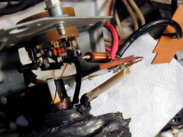
You customarily measure cathode current by disconnecting the cathode
lead (pin 8, in this case) of the HOT and putting a milliammeter between those
points, using a .1-mfd capacitor to bypass AC.
In the next photo, I have unsoldered the pin 8 lead and temporarily installed
the capacitor between that and its ground connection (shared by the nearby damper tube).
I'll use an analog meter because some digital meters can't give a correct reading here.

Using my Triplett 630-NA analog multimeter,
I measured about 118ma, right in the middle of the desired range. Good news, and
this relieved my anxiety about overdriving the flyback. I removed the temporary
capacitor, put the chassis back in the cabinet, and resumed using the TV.
A week and a half later, I happened to acquire an
HP 428B DC milliammeter, which makes
the measurement even easier. Rather than unsolder the cathode lead, you
merely clip the meter's probe over the HOT's plate lead (typically
marked DO NOT MEASURE in schematics). In this photo, the 428B is sitting
on the floor, with its probe clipped to the 6DQ6GTA tube's lead toward
the rear of the chassis.

This high-precision instrument confirmed that my earlier measurement
was correct. On this set, the Width control directly affects the HOT output,
and thus, the current drawn by that tube. Since I was able to take this reading with the
chassis in the cabinet, I could observe the picture width while making
the adjustment.
Flyback Relapse!
After playing many hours without skipping a beat, one day my repaired
flyback failed without warning. Suddenly, the screen went dark and I
heard an ominous hissing, squealing noise. After powering down,
I popped open the HV cage lid and turned the set back on in a darkened
room, one hand on the power cord. Just as before, a fat blue arc
shot out the side of the doughnut toward the cage.
Well, it was a good try. Perhaps the old flyback had some shorted
windings after all, which eventually caused overheating and
arcing despite the new insulation. When such shorts are buried
deep in the coil, they're impossible to repair.
Removing the old flyback was more trouble than installing the new one.
In the next photo, I have removed the HV cage and loosened the flyback frame
from the chassis. Notice the thin metal strip projecting from the frame
bottom. Its ends go through slots and then are bent over to secure the flyback.

I will also unscrew the nearby 1B3GT rectifier socket from its
insulator cup, gaining access to the underside to install the provided filament
loop, a length of insulated wire that goes once around the flyback core.
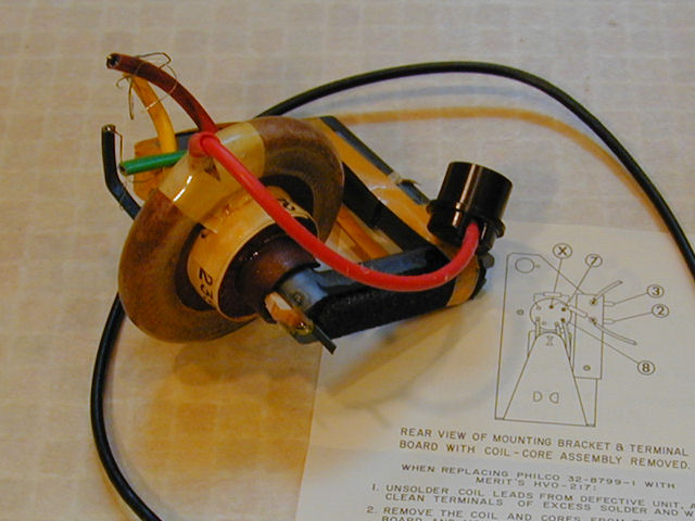
The new flyback is a complete replacement. Its coil is significantly
thinner than the original and it has a clear plastic insulator rather
than a wax coating.

Here, I have mounted the new flyback in its frame and soldered the new
filament loop to the rectifier socket. After soldering the new leads to
the correct terminals, it will be time to put everything back together.
This job would be slightly easier with the frame completely removed
from the chassis, but I didn't want to unsolder all of the other leads from
the yoke connector that stands above the flyback. Why disturb
such things if you don't have to?

The new flyback is ready to go. I'll put the HV cage back on, reinstall the
chassis, and give it a whirl.
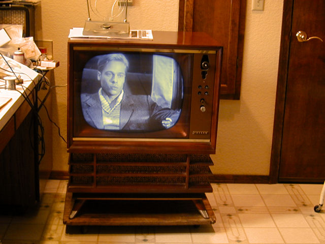
Here's the television after installing the new flyback. Lookin' good!

At this stage, the Miss America TV played happily without incident.
I initially thought the audio bass somewhat weak, but when I put on the
back cover, the bass increased significantly, something I should have recalled
from experience.
A New Picture Tube!
In 2014, I had an opportunity to buy a new picture tube for this set. With the old CRT,
the screen started out completely dark and took four or five minutes to light up.
And when you increased the brightness to a watchable level, the highlights took on
the telltale silvery distortion seen in a worn-out tube.
I paid the seller $100 for the tube plus $45 to ship it across the US. That seemed a fair
price in today's (2014) market, considering that nobody in the world can rebuild worn-out vintage CRTs.
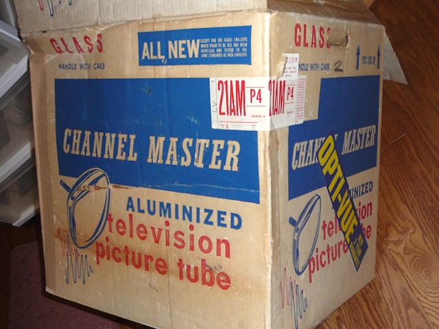
The tube was shipped in its original carton, enclosed in a second box.
The new CRT is a factory-rebuilt Channel Master 21AMP4A
with an aluminized screen, a good replacement for the original 21BSP4.
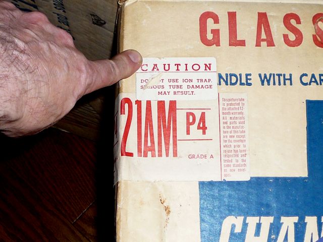
The box declared that it was all new except for the glass envelope, which had been inspected and tested.
Another label reminded me not to use an ion trap magnet, which is unnecessary
with an aluminized tube and the type of electronic gun used in this rebuild.


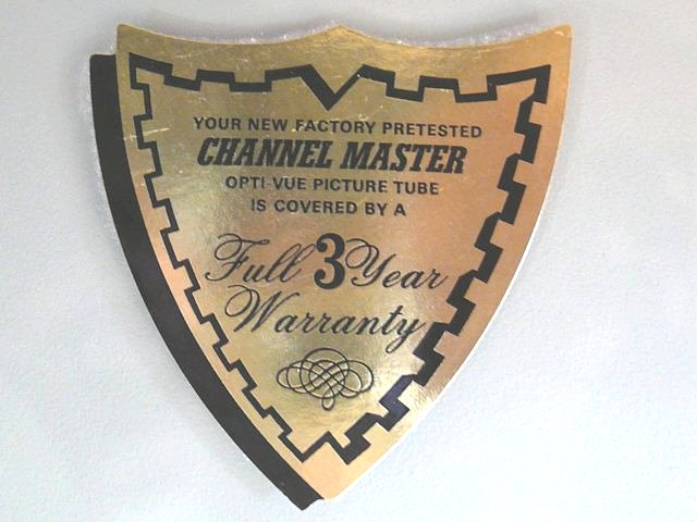
The box also contained the tube's warranty card. A sticker on the CRT
face advertised its three-year guarantee.


My Sencore CR70 tester shows strong emission, as you'd expect from a new tube.

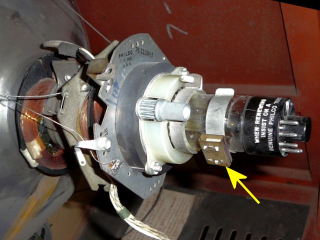
Before removing the old tube, I'll note the position of the neck hardware.
The yellow arrow points to the unneeded ion trap magnet.

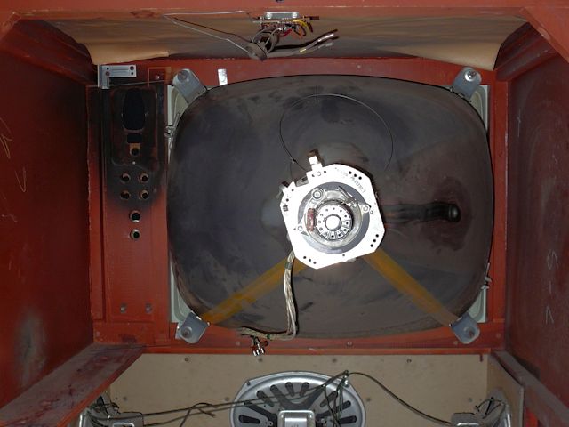
I'll replace the tube with the chassis removed and the cabinet lying face-down on a carpet.
The CRT is held in place with a heavy steel band around its front perimeter,
secured to the cabinet with four corner bolts.

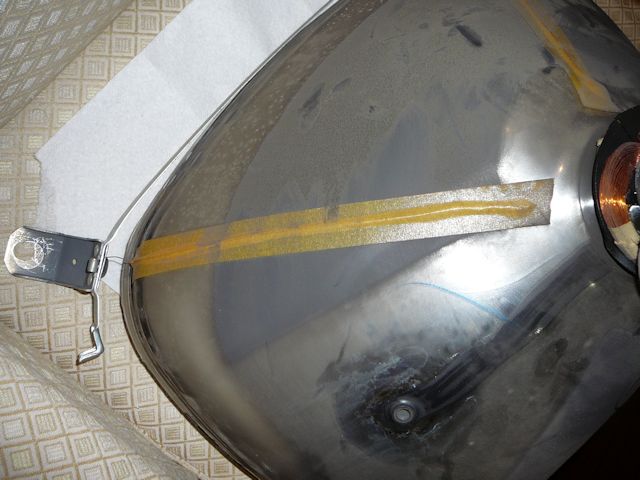
In the next photo, the old CRT has been removed. Two taped grounding wires connect the
CRT bell to the retaining band. (The upper and lower parts of the band connect to the
chassis with long springs.) These wires make a ground connection for the CRT's conductive
aquadag coating, allowing the inner and outer coatings of the CRT to act as
a capacitor in a filtering circuit.

Before setting the new tube in place, I carefully cleaned the inside of the safety glass and the CRT's
face with denatured alcohol. After installing a new picture tube, the last thing you want is
to see a big thumb smudge or streak of soot in that inaccessible area between the tube and its
safety glass.
Reinstallation is the reverse of the removal procedure, in the words of many old service manuals,
a statement that I sometimes found annoying, but in this case, there really wasn't any
more to say. Here is the new CRT in place, ready to accept the chassis.

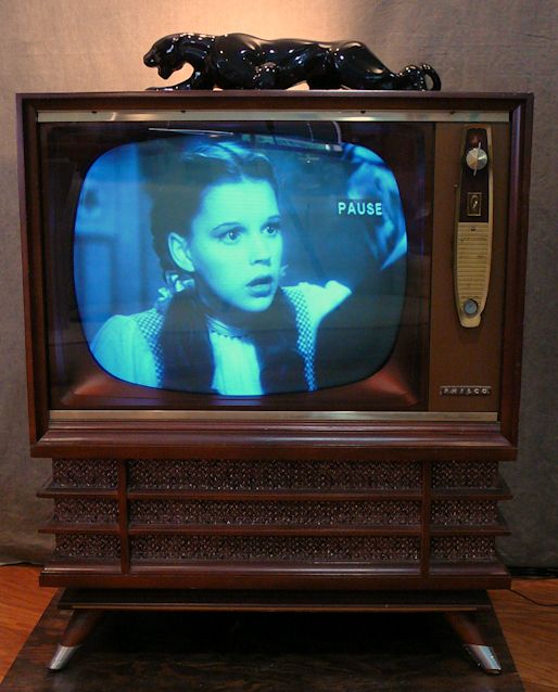
A little while later, we're all hooked up and the new CRT is looking good. I had forgotten to take
a "before" photo with my digital camera, but I did take a snapshot with
my iPhone, so I took a second phone pic of the new CRT for comparison.


You can see how the new CRT has much better contrast. Its darks are closer to black,
as they should be. The next day, I took a photo with my digital camera, which unfortunately
makes black and white screens look very blue.

The blue tint is an over-correction by my camera, which I have noticed
in photographing many other black and white TVs. I guess the camera adjusts to
the background colors in the room, and applies the same adjustments to the screen,
making it look weirdly blue.
You can fix such photos to make both the cabinet and the screen look normal.
With an art program (I use Paintshop Pro), simply cut out the screen image and convert
it grayscale, then paste it back into the cabinet image.
At the same time, you can lighten the cabinet portion to look normal.
Yes, the second photo has been modified, but that's what the TV looks like in real life!
I simply eliminated the weird auto-correction from my camera,
which produced an image that doesn't match what our eyes see.
Final Thoughts
This Miss America is a winner. It's one of the best-performing black and white TVs in
the house and its chassis is easy to work on. With a new picture tube, flyback
transformer, and capacitors, it should be enjoyable to watch for years to come.
|