Hoffman Model 7M112 Tabletop Television (1952)


This Hoffman model 7M112 tabletop is an interesting early 1950s television. Although the
cabinet may not win any beauty prizes, it's a surprisingly good performer with a
bright picture.
Hoffman was a small manufacturer based in Los Angeles. You can read a little of their
history at the tvhistory website.
Perhaps Hoffman TVs are more common in California, but I have seen very few of them here in
Washington state.
I noticed this set in a local craigslist ad and bought it for $20 from a guy who
said his friend had been using it until recently. I take such stories with
a grain of salt, of course. In any event, the price was right, as long as the picture
tube wasn't a dud.
Description
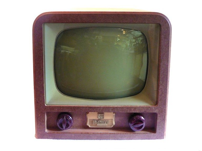
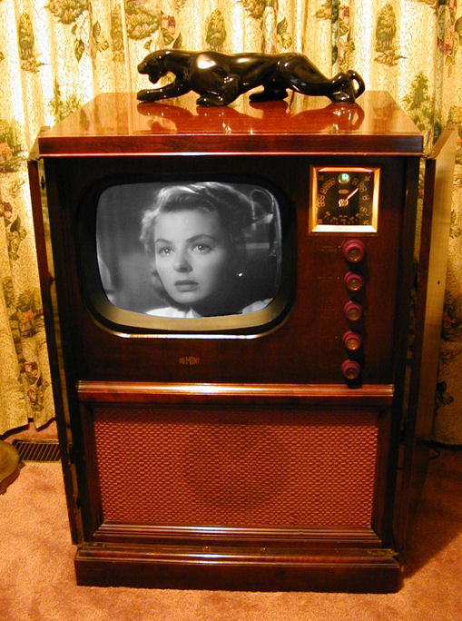
The 7M112 uses a 17-inch picture tube and the television is a cube, roughly
19 inches in every dimension. Don't let these photos fool you—this
TV is fairly large for a tabletop, and heavy for its size. For comparison, I included a
photo of my DuMont RA-113 console, which also has a
17-inch screen. If you took away the DuMont's speaker and right bank of controls, what you'd
have left is a TV the size of the Hoffman.
The controls are simple, with knobs for power/volume and contrast on the left and
channel selection and fine tuning on the right. Behind a small hinged door
are three knobs for vertical hold, brightness, and horizontal hold.
The cabinet is made of heavy Masonite (pressboard) with light wooden framing and a
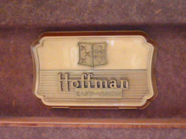
pegboard bottom. The control cover is made of plastic reverse-painted in gold,
declaring that this is a Hoffman Easy-Vision set.
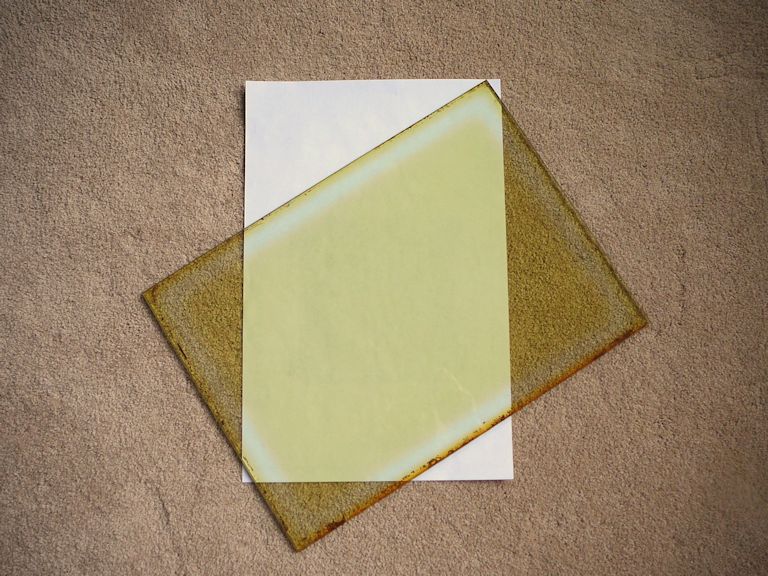
Easy-Vision was Hoffman's marketing term for a light green tinted safety glass.
The tint ostensibly reduced eye strain, although no other TV manufacturers
ever jumped on the bandwagon to copy this gimmick, and some people
find the tint a little distracting. Here is the glass when I
removed it for cleaning.

You can see some lighter lines along the glass where it touched the cabinet and was
protected from light. Who knows, maybe this glass was originally clear and the
plastic sandwiched between the glass panes faded to this color. In any case,
now it's a light greenish amber, and many other Hoffmans have similar glasses.
From this photo, you might think the TV makes a starkly green image, but in practice
the tint is barely noticeable. The main effect is to dim the picture a little.
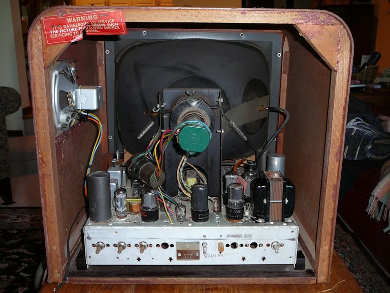
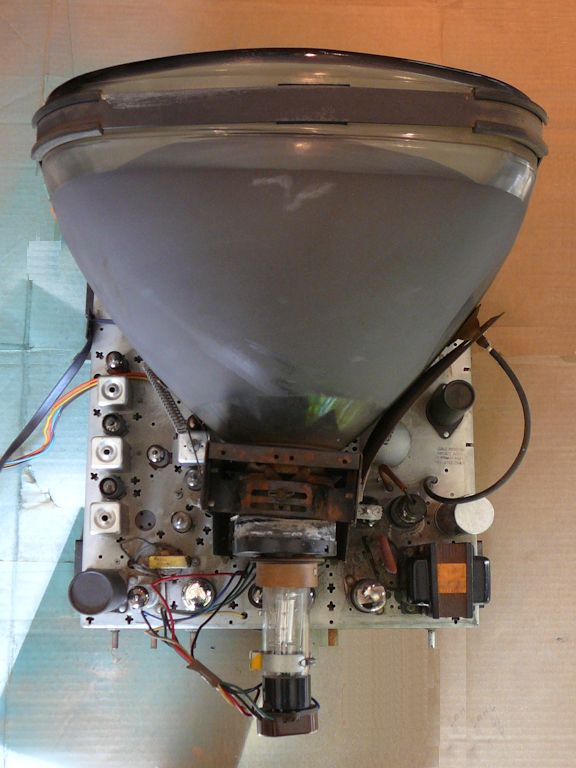
At first glance, the chassis appeared quite clean.
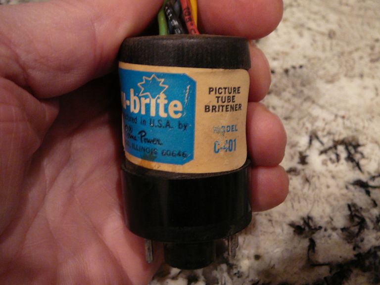
On the not-so-promising side, I saw a brightener hanging from the picture tube socket.
It is the cylindrical object hanging from colored cables to the left and
below the picture tube neck.

Brighteners were usually added
on a TV whose picture tube was nearly worn out, to squeeze a little more life from it.
I will be curious to see what my CRT tester says about this tube.
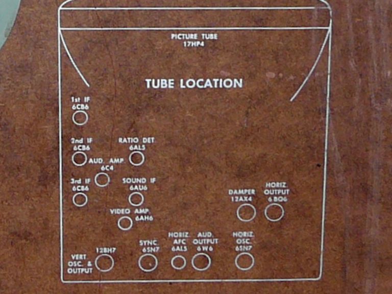
The cover shows the tube layout in white printing, while the model number (7M112)
is rubber-stamped, suggesting that Hoffman used the same (or very similar) chassis in
more than one model.

This is an eighteen-tube TV, including the type 17HP4 picture tube:
| Tube |
Type |
Function |
| V1 |
6CB6 |
RF Amplifier |
| V2 |
6J6 |
Mixer / Oscillator |
| V3 |
6CB6 |
1st Video IF Amplifier |
| V4 |
6CB6 |
2nd Video IF Amplifier |
| V5 |
6CB6 |
3rd Video IF Amplifier |
| V6 |
6AH6 |
Video Output |
| V7 |
6AU6 |
Audio IF Amplifier |
| V8 |
6AL5 |
Ratio Detector |
| V9 |
6C4 |
Audio Amplifier |
| V10 |
6W6 |
Audio Output |
| V11 |
6SN7 |
Sync. Separator / Inverter |
| V12 |
12BH7 |
Vertical Oscillator / Output |
| V13 |
6AL5 |
Horizontal AFC |
| V14 |
12AU7A |
Horizontal Oscillator
|
| V15 |
6BQ6 |
Horizontal Output |
| V16 |
12AX4GT |
Damper |
| V17 |
1B3GT |
High Voltage Rectifier |
| V18 |
17HP4 |
Picture |
Most of the tubes are located on top of the chassis, as shown on the cover diagram, and three more are hidden
under it (they are the 6CB6 RF amplifier, 6J6 mixer/oscillator, and 1B3GT high-voltage rectifier).
This TV uses a couple of solid-state components: a type 1N60 diode as a video detector and two
selenium rectifiers in the low-voltage power supply.
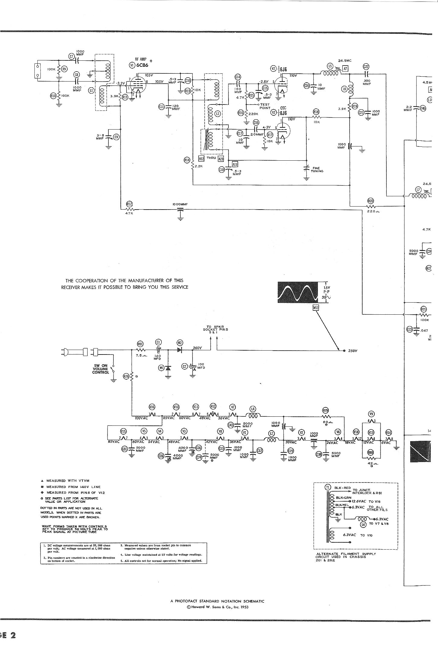
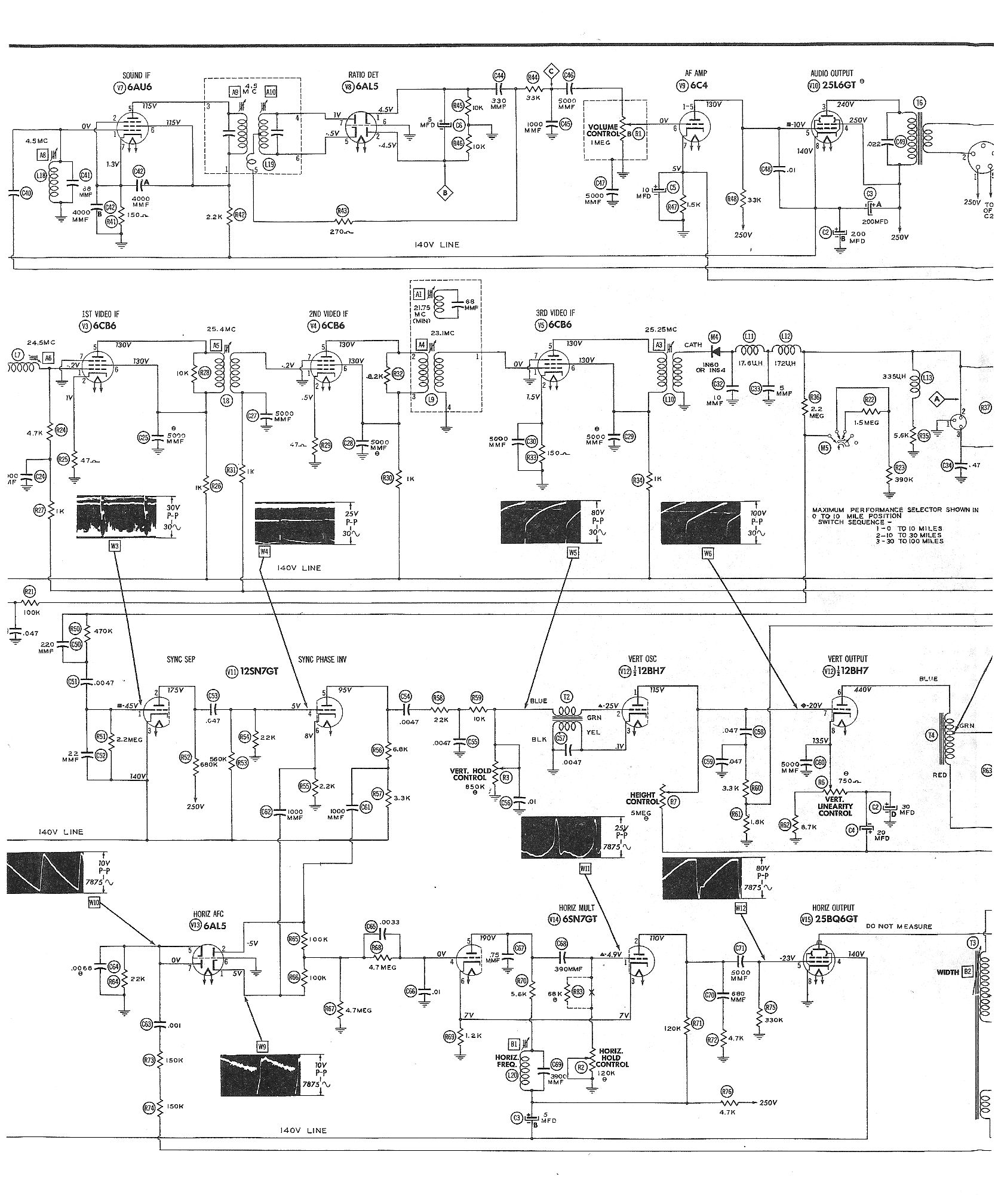
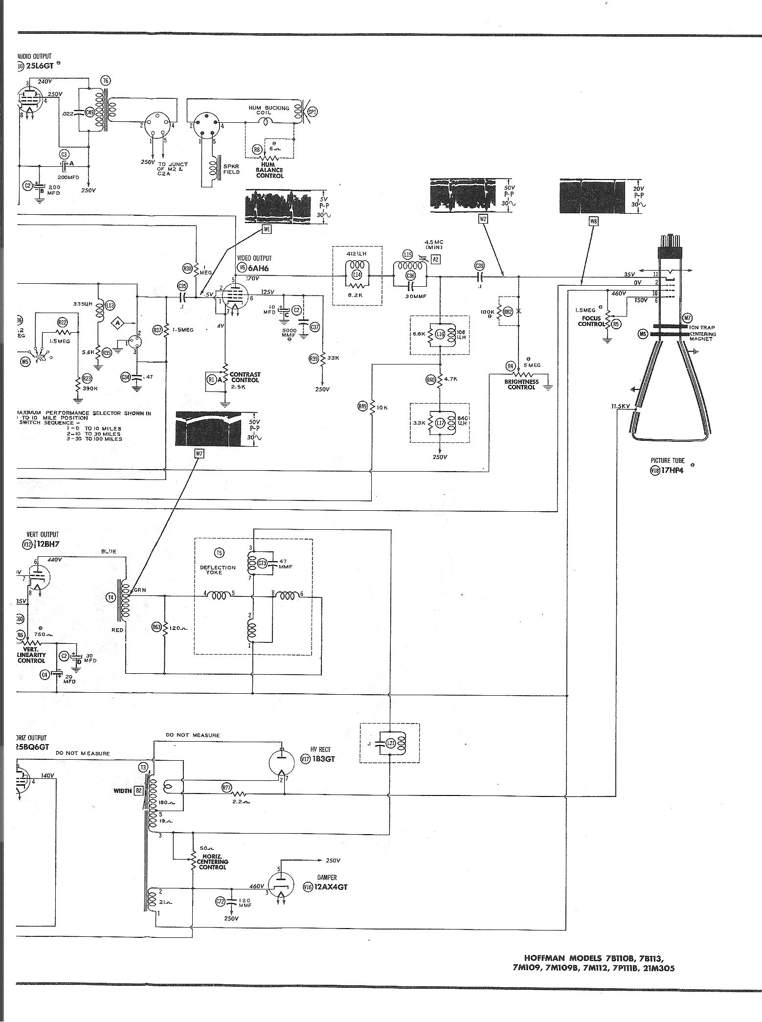
The service manual is Sams 205-5
and this article refers to parts by the numbers given in Sams. Here are scans of the schematic in three parts:
Page 1, Page 2, Page 3.
The manual covers seven different models with the same basic chassis. Some other models use a series-string
power supply where this one, with chassis 202, uses a filament transformer. The manual also shows a 25BQ6GT
horizontal output tube where my set uses a 6BQ6GT.
The overall electronic design, as well as the cheap pressboard cabinet, tells us this was an inexpensive television.
It lacks circuits for AGC (automatic gain control) and DC restoration, features that were standard
on better quality sets. It does have three IF (intermediate-frequency) amplification stages, however,
and a simple design doesn't necessarily equate to bad performance.
I'll reserve judgment until I get it working.
Under the Hood
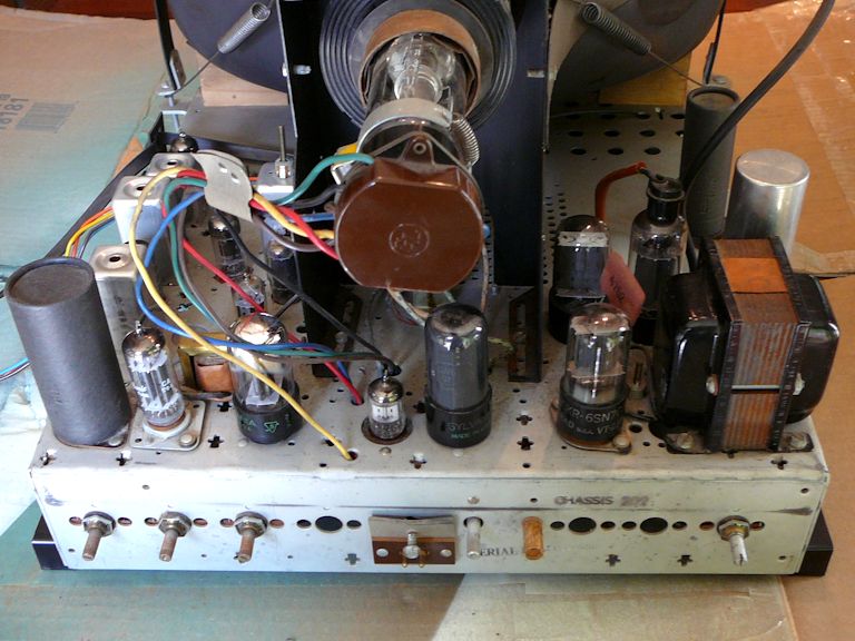
The next day, I removed the chassis. From above, we see the tube layout pictured on the rear cover.
At lower right is the smallish power transformer, which supplies filament current to
the tubes, but no B+ voltage.

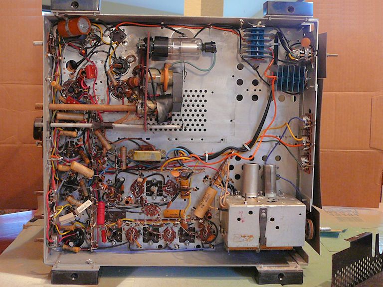
Under the chassis, we see plenty of empty real estate. The uncluttered layout illustrates one
advantage of working on a bare-bones television.When a TV has fewer parts, they are usually easy to reach!
Now we can see the hidden tubes. At lower right is the tuner with
its two tubes. I'm delighted to see that is a sturdy turret-style tuner. Thankfully, Hoffman
didn't skimp on that crucial component. I have removed the
high-voltage cover near the top to reveal the 1B3GT high-voltage rectifier tube. When in
place, the cover also encloses the bases of the 6BQ6 horizontal-output and 12AX4GT damper tubes.
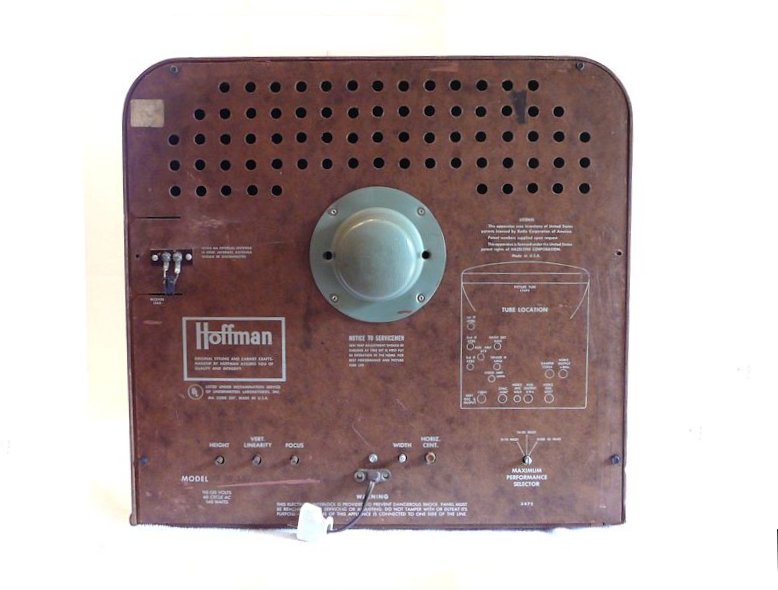
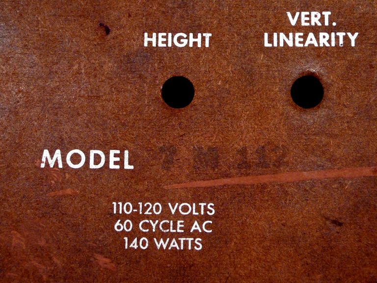
The TV has six controls on the back panel. From left to right, they are height, vertical linearity,
focus, width, horizontal centering, and a three-position range switch.

On some other models, the three front controls (vertical hold, brightness, horizontal hold)
are relocated to this back panel. You can see the empty holes where they would be
mounted.
The range switch lets you adjust the degree of IF amplification for stronger or weaker stations.
The three ranges are 0-10 miles, 10-30 miles, and "up to 100 miles" in the optimistic words of the manual.
It's nice to have this switch, but it's kind of a cost-saving copout.
More elaborate TVs use an AGC (automatic gain control) circuit to automatically adjust
for differences in signal strength as you change channels.
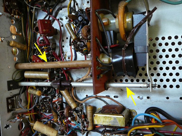
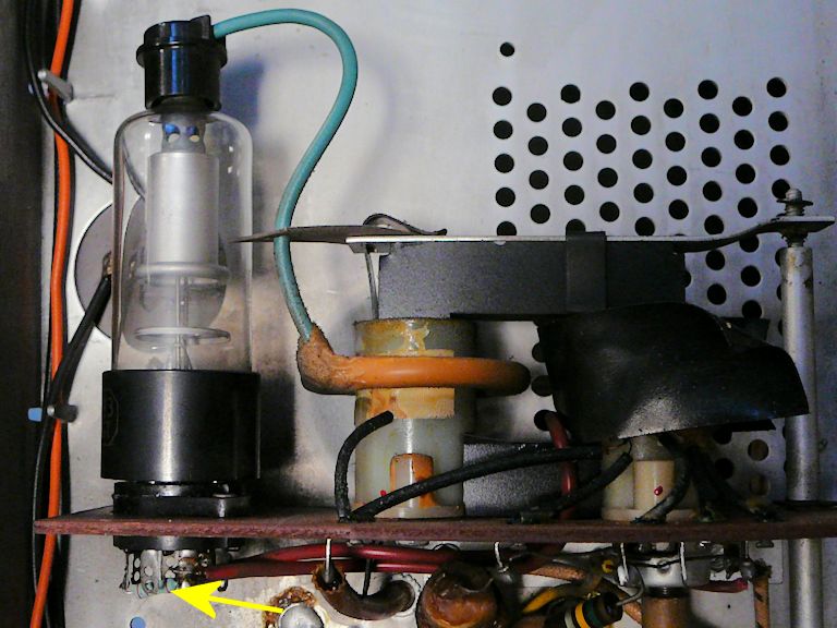
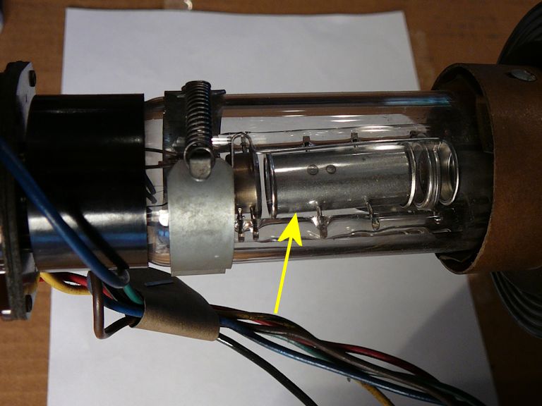
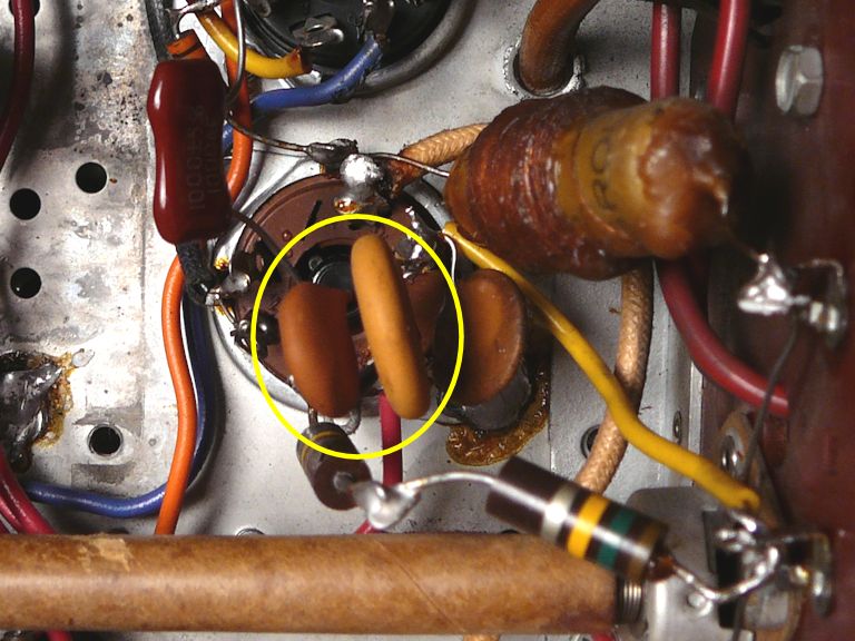
The width control is rather unusual. Seen from under the chassis, the lower yellow arrow points
to its shaft. (The upper control shaft is for the horizontal centering potentiometer.)

The rightmost end of the shaft is threaded and it connects to a lever fastened to
the flyback transformer's core. Turning the control moves the core in and out,
changing the size of the transformer's air gap. This directly changes the high-voltage
output level.
Calling this a "width" control is a bit of a misnomer.
As I noticed after making the set operational, changing the HV level makes the
entire screen image shrink or grow, so "width and height" control would have
been a more accurate name. However, there is an independent control for adjusting the height,
so in practice you can set the width with this control and then use the other control to
tweak the height as needed.
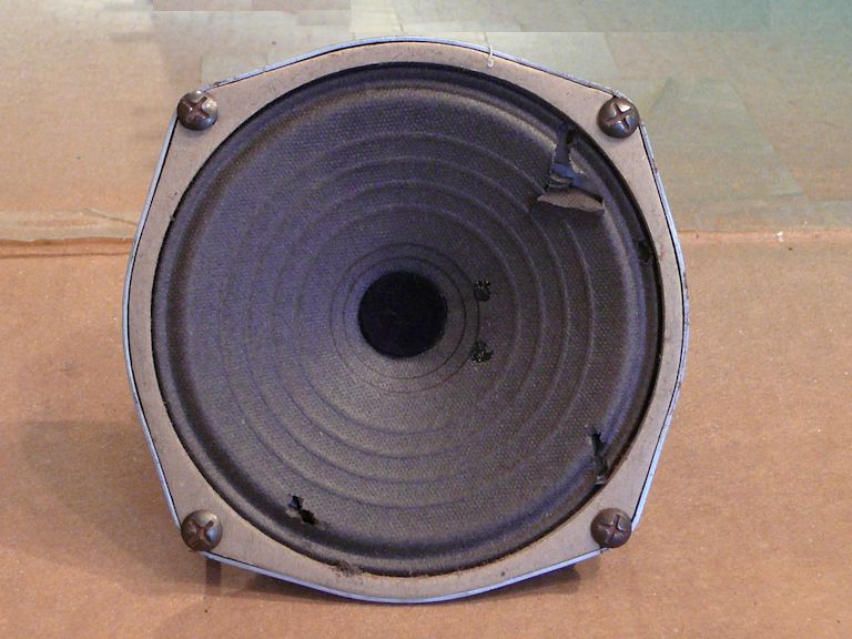
The speaker cone has three small pokes but those will be simple to
patch with tea bag paper and flexible glue.

I'm a little curious about how these were made, since the speaker grille cloth doesn't have any visible
holes. Perhaps a serviceman carelessly tossed the speaker onto something when working on this TV.
If you want to power up the chassis on the workbench, you need to remove the speaker from the
cabinet and plug it in. Its field coil forms part of the 250-volt B+ circuit and
the TV won't operate if it's unplugged.
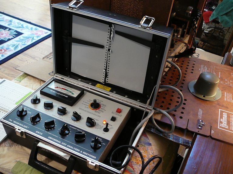
Testing the Picture Tube
Before spending any time restoring this TV, I want to know if the CRT is usable.
I unplugged the brightener to test the picture tube on my Sencore CR70 tester.
As often happens with long-unused TVs, the picture tube looked pretty dead at first,
but within a minute or two, the emission looked quite strong—nearly as good
as a brand-new tube.

That's excellent news, since I could easily spend far more than the $20 purchase
price to buy a new CRT if this one were unusable. Good picture tubes don't grow
on trees and the 17HP4 is not a common CRT. In the old days,
you could send a tired tube out for rebuilding, but the last CRT rebuilder
in the world went out of business in 2013.
Who knows why a brightener was put on a perfectly good tube? This might be
the work of a hopeful do-it-yourselfer, or perhaps a lazy repairman was
trying to compensate for some other problem. I'll toss the brightener into my
box of spare whatnots. This tube should produce sufficient brightness all on
its own, and running the tube at unnecessarily elevated filament voltage would only
shorten its life.
Repairs Ancient and Modern
A closer look shows that this TV has been serviced before, probably multiple times.
None of the tubes bears the Hoffman Easy-Vision stamp—they have
various brand names—and that's a modern resistor under the socket of the 1B3GT high-voltage
rectifier tube.

That particular resistor often fails. I remember replacing it in one of my
first restorations, an RCA 630TS.
This replacement looks tidy and the value of the resistor is correct.
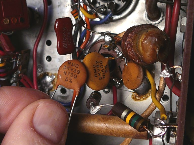
Looking elsewhere, the news is not so good.
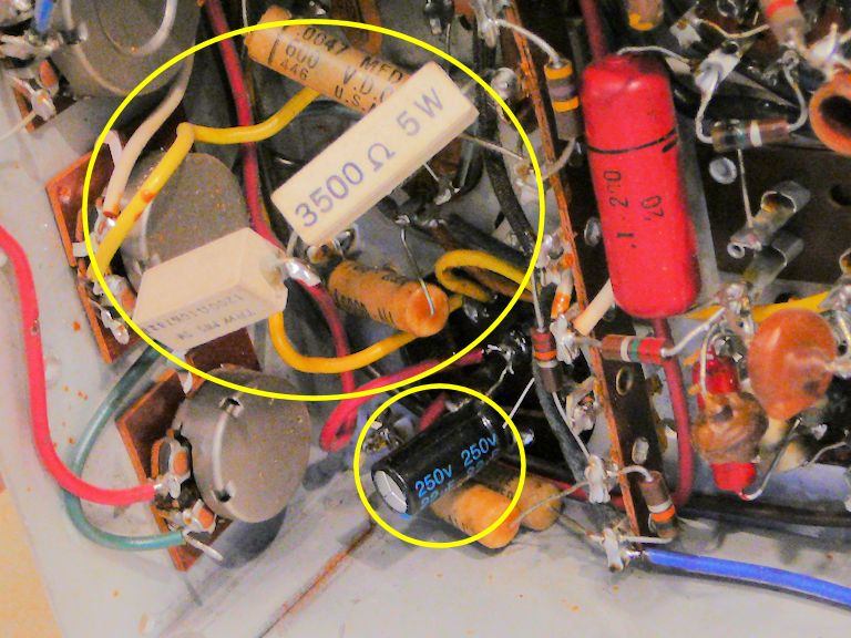
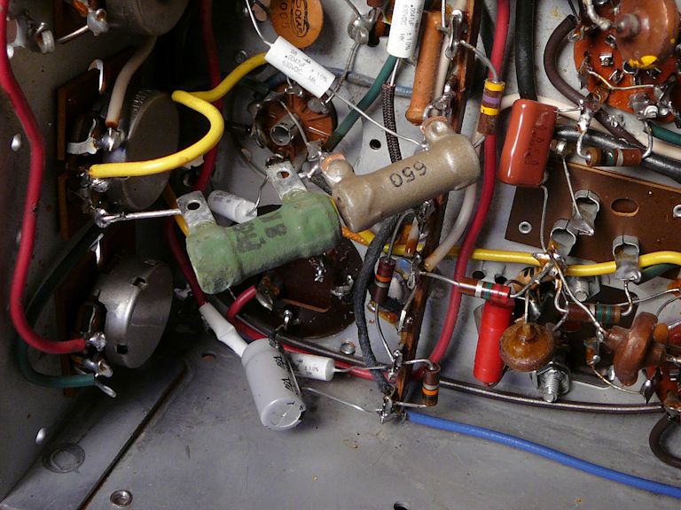
In the next photo, the circled parts are recent replacements: a modern electrolytic
capacitor and two power resistors wired in series. To their right is a
pink "Big Chief" capacitor, an older type that was likely installed
years earlier. Also visible in this photo are a few of the original wax paper capacitors:
"Good-All Marbleites," a brand I hadn't seen before.

Both of the circled replacements
are incorrect. The repairman wired a 3.5K resistor in series with a 1.2K resistor,
making a 4.7K resistor. That's a common value, but the schematic calls for an
8.7K resistor—pretty far off! After the original resistor failed, perhaps that's the closest
he could come to the right value, using the parts on hand. This resistor connects to one end of the
vertical linearity control, so I'll watch for linearity issues when I get the
TV working.
The electrolytic capacitor replacement is also a tad peculiar. The original electrolytic (C3) is
a 5-mfd cap connected to the horizontal circuits. The replacement is a
22-mfd cap, more than four times the correct value. Even worse, instead of disconnecting
the old cap, he wired the new one in parallel with it. This effectively adds
the two capacitance values, so if the old cap is still good, now we have a 27-mfd cap
instead of 5 mfd. Or, if the old cap shorts out, we'll
have a short circuit. Again, perhaps he was just sticking in available parts until
he got the picture to stabilize. And, to be fair, in some circuits the value of an
electrolytic is not too critical.
Not to worry. Both of these uglies will be easy to reverse when the time comes.
Start With the Basics!
Before replacing anything, or trying out the TV, I went through the usual startup drill, testing all
of the tubes and replacing any bad ones, cleaning controls, and so on. You
can read more about those preliminaries in the article,
First Steps in Restoration.
As often happens, nearly all of the old tubes were still usable.
I only needed to replace two of the 6CB6 IF amps and a 6AL5 horizontal AFC tube.
The Mysterious Green Glow
When I first tried powering the TV, it produced excellent audio, a sign that its
low-voltage power supply was operating and that the tuner, intermediate-frequency, and audio circuits worked somewhat.
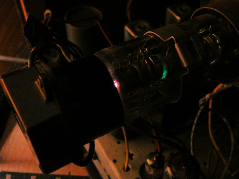
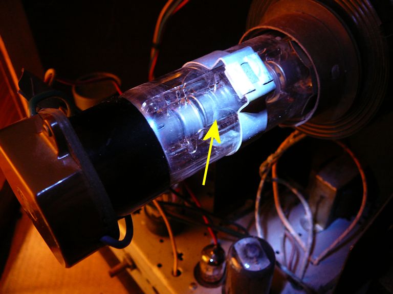
But the screen was completely dark and I found no trace of high voltage. I tried moving
the ion trap magnet to light up the screen, and noticed a strange green glow
inside the picture tube's neck:
The glow was only visible in a dimly-lit room. When I shined a flashlight on the CRT neck,
I could see a faint strip of something on that tube element.

Green phosphorescence from tube elements was new to me. Most tubes glow orange, of course,
when their filaments heat up.
There are green "magic eye" tubes in a number of my radios, and a couple of
TVs, but in those the phosphorescence is on the tube's face, not its internal metal
elements. Some voltage regulator tubes in my communications
radios glow various colors in normal operation; they are gas-discharge tubes and the
color depends on what gas is used to fill them, but that color is never green.
When I mentioned this curiosity in a VideoKarma
discussion,
I learned that a few picture tubes had green phosphor on a tube element as an aid
to adjusting the ion trap magnet. One of the forum members (jr_tech) even located
a US patent
(2,627,047)
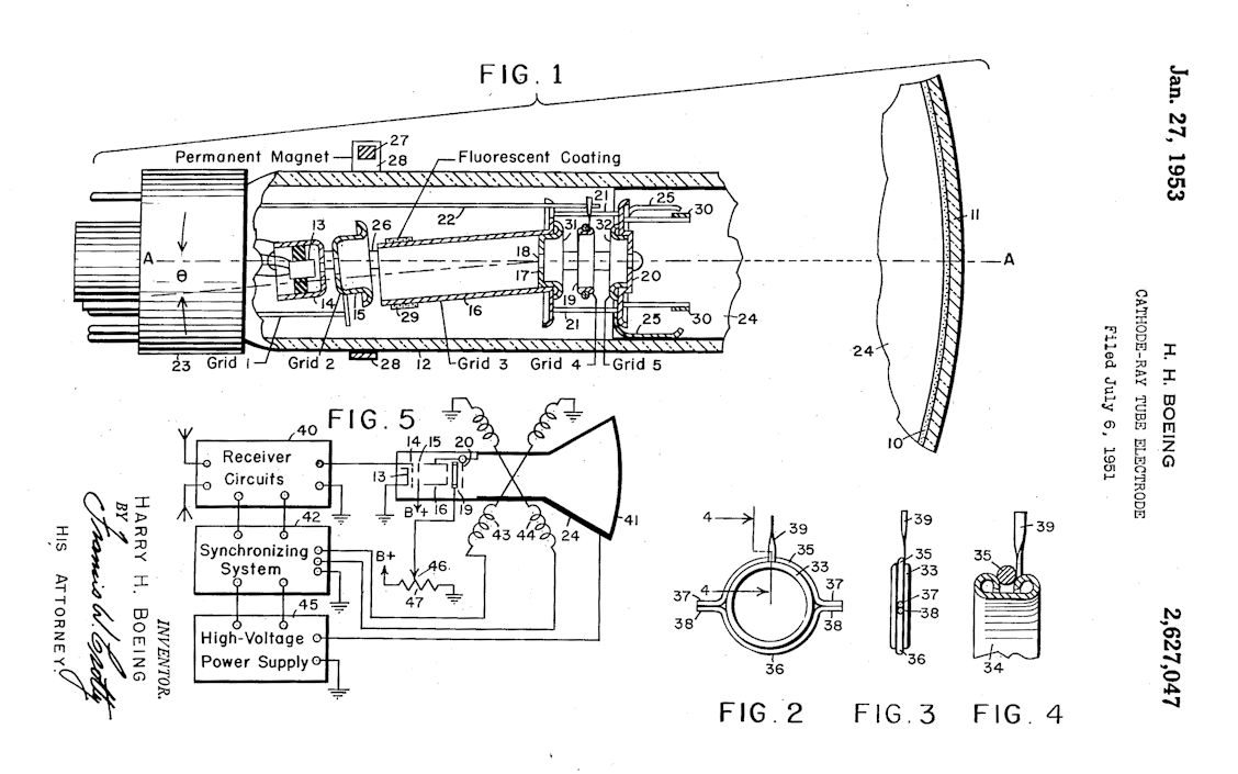
from the Rauland company that mentioned it. Here is the
patent drawing that describes a "fluorescent coating" (item 29) on the tube element labeled Grid 3.
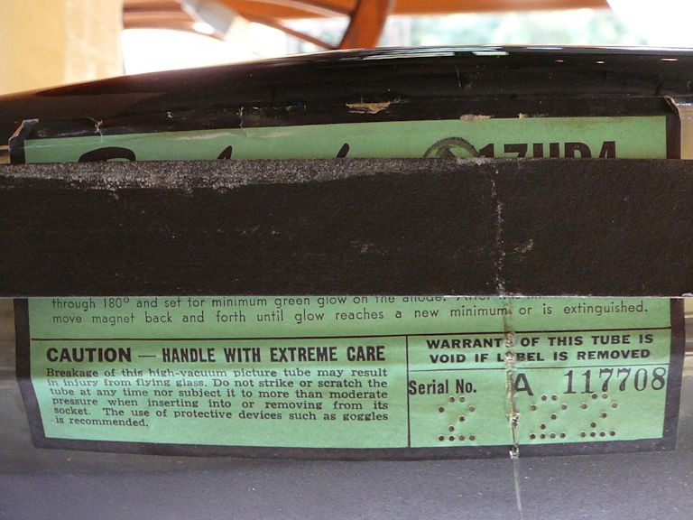
Sure enough, my picture tube is a Rauland! Looking closely at a green label,
I saw the Rauland name (mostly obscured by the retaining strap) and instructions for using
the green glow to adjust the ion trap magnet. You rotate the magnet
on the CRT neck to minimize the glow, and then slide it forward or back until the glow
is minimized or extinguished.

With a conventional picture tube, you follow the same procedure, of course,
but you watch the screen's brightness rather than a glow on the neck.
On reflection, the glow seems more gimmick than necessity, somewhat like the green magic eye
tuning indicators in my DuMont TVs
(RA-103 and RA-113).
Yes, the green indicator works, but you also have a great big "magic eye" in front
of you—the picture tube itself—and most people naturally look at that rather than the
secondary indicator.
The Rauland company (a successor to the original) still exists, by the way.
A history page in the current
company website states that Norm Rauland founded the company in 1924.
Rauland acquired Baird Television in 1942, made radar equipment during World War II, manufactured CRTs in the
post-war years, and was acquired by Zenith in 1948. The
founder went on to start a new company that still operates under that name.
The name Baird is even more prominent in TV history.
John Logie Baird
was a pioneer in mechanical TV and early electronic TV. So, in a roundabout way,
this odd picture tube, used by an obscure California company, can trace corporate
connections back to the very infancy of television development.
What Is an Ion Trap Magnet?
In case you are wondering, an ion trap magnet is used in picture tubes whose elements are angled
to prevent "ion burn" on the screen. The image on a TV screen
is created by a moving stream of electrons emitted by the tube's electron gun (cathode),
and that gun also emits ions that are destructive to the phosphors on the CRT's face. If ions are
allowed to hit the face for many hours, they eventually burn a dark area in the middle of the screen.
The magnet takes advantage of the fact that ions are heavier than electrons.
The manufacturer positions the electron gun at an angle instead of pointing straight at the screen face.
The mixed stream of ions and electrons shoots toward the tube neck at an angle
and the ions escape harmlessly.
What you have at that point is a dark screen, since no electrons are striking its phosphorescent
face. But the lighter electrons are easily diverted by a magnetic field. (That's how TV works
in the first place, by magnetically sweeping the electron beam across the screen.) Thus,
if you place a magnet at the right place on the tube's neck, it redirects the electron stream
to shoot directly at the screen and light it up. The heavier ions are not affected by the magnet,
so they continue to shoot away at an angle.
The Rauland patent drawing showed how this works, so let's look at it again:
In the drawing, notice how the tube elements labeled 13-16 are fixed at an angle in the tube neck.
A dashed line running through them shows the angle of the undiverted electron-ion beam. The ion
trap magnet is labeled Permanent Magnet (items 27 & 28). When positioned at the right spot,
the magnet redirects the electron stream to follow a straight line (labeled A) perpendicular
to the face of the screen. The screen lights up from the scanning electron beam and the harmful
ions escape into the ether.
The term "ion trap" is a little misleading, since the ions are not trapped at all. The angled
gun shoots them off to the side where they do no harm. Some TV manufacturers called this magnet a
"beam bender," a more accurate term, but ion trap is the common parlance.
The Screen Lights Up!
This was all rather fascinating, but meanwhile the TV was completely unrestored.
While I waited for the schematic to
arrive in the mail, it couldn't do any harm to replace the paper capacitors in
the sweep sections (vertical and especially horizontal), as well as the sync
section that feeds them. I could identify those tubes from the layout on the
back cover, and replace their capacitors by reading the values on their cases, as explained
in my recapping article.
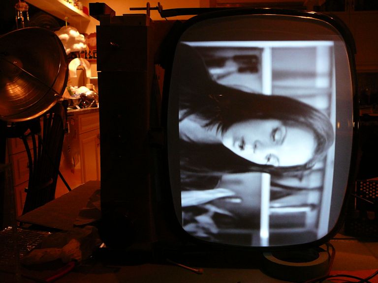
After replacing that handful of caps, I tried the TV again, moving the ion trap
magnet around until the screen lit up. I was delighted to
see the following (the images are sideways because I had placed the chassis
sideways to work on it):

Yippee! Those were terrific images, considering that the TV was still largely unrestored.
Now that I had an image to work with, I could examine the mysterious green glow
more closely. Just as explained on its label, the picture tube produced the brightest image
when I moved the ion trap magnet to make the glow as dim as possible.
The following animated .GIF image shows the green glow changing when the magnet is
moved, with consequent changes in screen brightness. When the green glow diminishes,
the picture tube brightens up. (The orange glow is the normal
color of the tube's filament.)

Here's another photo of the phosphor layer:

The fluorescent coating is nearly invisible in normal room lighting and it doesn't glow very brightly.
If I hadn't happened to try the set in near darkness, looking for any faint light from
the screen, I might never have noticed it.
Out with the Bad, In with the Good
I went on to replace all of the remaining paper capacitors, plus a few electrolytics,
retrying the TV occasionally to make sure I hadn't miswired anything. I also replaced a
few out-of-tolerance resistors. The TV's performance continued to improve, becoming
more stable and more watchable in small increments.
Speaking of resistors, here's another shade-tree fix that would have been easy to overlook.

The original is a 120K resistor (R71) that connects to the horizontal oscillator tube's plate.
The repairman wrapped a 100K resistor around it in parallel. After I separated the resistors, I found
that the original had drifted up to 131K, so I guess he was trying to compensate for that
change and make things work. However, the combined resistors measured about 57K, far from
the specified value. The TV worked with that odd couple in place, but it worked better
when I restored the correct value.
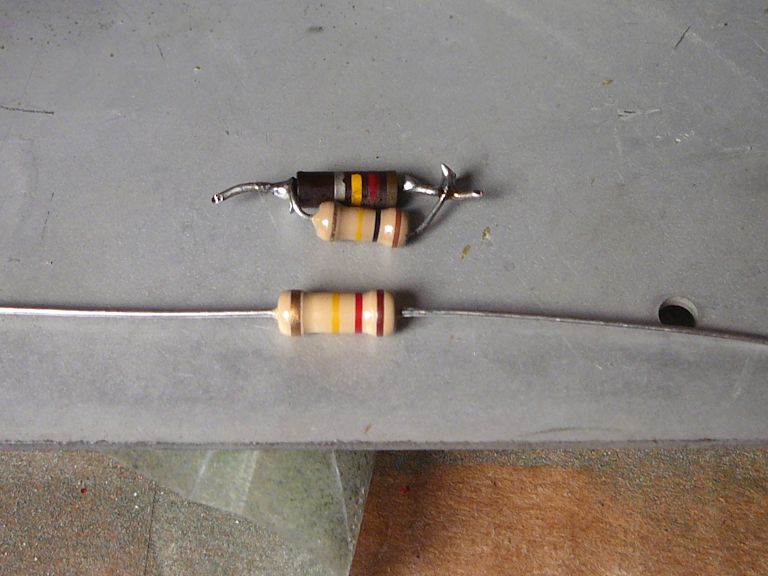
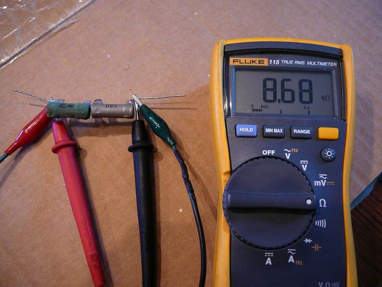
The vertical linearity couldn't be adjusted correctly until I replaced the funky
power resistors that I noticed earlier (first photo below). At a local surplus store I
found two resistors that added up to 8.7K, the rather unusual value specified for R62.
These are a little funky looking, too, but now the vertical linearity adjuster has
a normal range.


At this stage in the project, the high voltage supply was stable,
the picture was bright and focused, the contrast and brightness controls operated within
normal ranges, and the height and vertical linearity were just peachy.
Bumping Up the Width
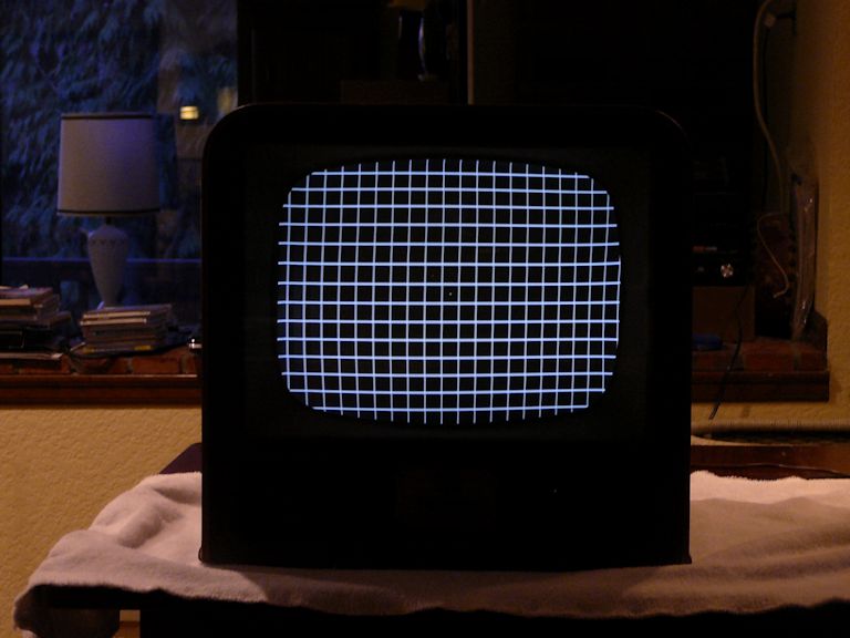
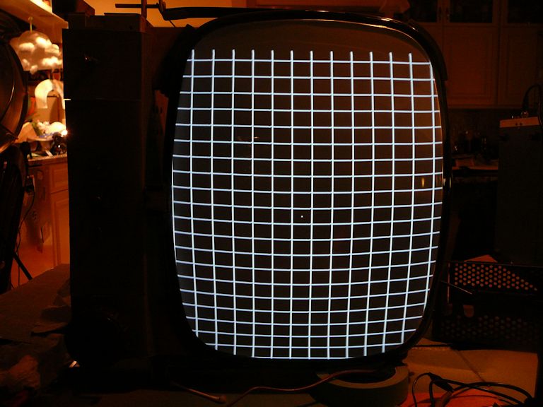
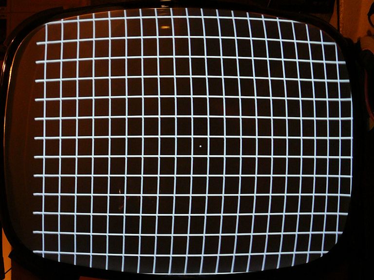
The sole remaining issue involved width and horizontal linearity. The width control
worked as expected, but the maximum width wasn't quite wide enough to fill the screen mask.
The horizontal linearity was also a little bit off. In this photo, notice how the
squares in the rightmost part of the screen are compressed, more like rectangles than squares.

Screen geometry adjustments are interactive, and in a TV with a horizontal linearity control, you would
typically alternate adjustments between the width and linearity controls, as well as the horizontal
centering control, until the width and linearity were just right and the test pattern was perfectly
centered.
This TV has no horizontal linearity adjuster. Presumably, when everything is working right,
the fixed-value components create an image with reasonable linearity. The degree of
non-linearity shown in the previous photo wouldn't bother most people when watching a program,
and some early TVs were known to have less-than-perfect horizontal linearity, even when
brand-new.
The deficient width is a bigger problem. When the TV is put back into the cabinet, Even casual viewers
will notice if there are blank strips between the sides of the image and the screen bezel.
When working with the width control, I was able to vary the high-voltage level at the second
picture tube anode from about 8.5KV-10KV. That's a little weak—the manual calls for 11.5KV—but
if the screen image is bright with strong contrast, I'm not going to quibble over numbers.
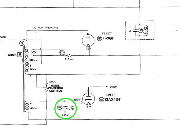
One suggestion from the VideoKarma forum was to try increasing the size of the capacitor
connected across the 12AX4GT damper tube. In the Sams schematic, this is capacitor C72.

(The schematic shows pins 3 and 5 unconnected, but notice that both pins connect to the 250-volt
source. In practice, C72 is wired between the two pins and pin 5 is connected to the 250-volt line.)
The voltage rating for that capacitor is 3KV. Although I don't keep many high-voltage caps
around, I found two 82pf caps rated for 5KV. Wiring one of them between pins 3 and 5 of
the damper did improve the linearity, stretching out the right half of the screen somewhat.
Naturally, stretching part of the screen also increases the overall width. After making
that modification, I could almost fill the screen—but not quite.
I tried adding the second 82pf cap in parallel with C72, but that was too much. Now, the
image more than filled the screen, but the high-voltage level was reduced so far (down to 7.5KV)
that the screen brightness suffered.
The next day, I picked up some more high-voltage ceramics from a local surplus store.
Since 82pf + 82pf was too much, let's try a smaller addition—say, 39pf.

That did the trick! I could adjust the width to fill the screen with just a bit of
overscan. Adding two capacitors between pins 3 and 5 of this tube made a tight fit, but
the results were worth it.

Since 82pf + 39pf = 121pf, I basically doubled the size of the original 120pf capacitor.
If I'd had a 120pf cap on hand, I could have used that in place of these two, but I
used what was available. After complaining about shade-tree modifications, I ended up
making a modification of my own! The final test is how well the TV works, of course.
If I wanted to spend a lot more time on this set, I might be able to
solve the problem another way. For example, I could try replacing C73, the tiny capacitor
buried in the deflection yoke, or try tweaking components on the horizontal output tube.
On the other hand, this bare-bones TV might not have had perfect geometry
when it left the factory. If a TV has a minimum of parts, that leaves fewer
parts to experiment with, and I have a lot of other projects waiting for attention. The
picture looks acceptable, so I'll stop here, for now.
Final Thoughts
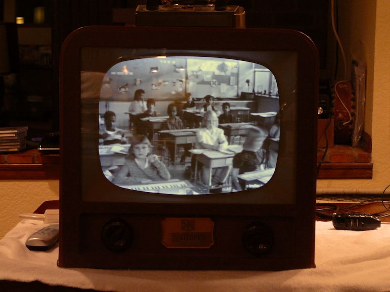
The last two photos show my little Hoffman after restoration. The image is bright and
the screen geometry is pretty regular. In the second photo, the television is receiving a live broadcast
from my home TV transmitter using rabbit ears.
In the end, I got more than $20 worth of entertainment from this little TV. Nobody will
mistake it for a DuMont, but it works well, within its design limits, and restoring it
gave me an opportunity to learn about the mysterious green glow.
And now, on to the next project! I'm waiting for my workshop to be remodeled so that I can resume
work on a more interesting (and complicated!) RCA CTC-4 color television.
|