Heathkit Model W-6M High-Fidelity Amplifier (1957)


Talk about big iron! This Heathkit W-6M monophonic amplifier was at the top of
many shopping lists in 1957. Teamed with a Heathkit
WA-P2 preamplifier,
and FM-3 Tuner
it formed the core of many a hi-fi enthusiast's dream system.
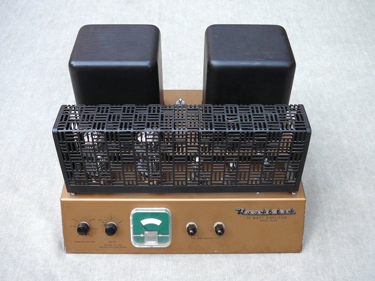
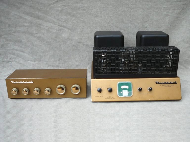
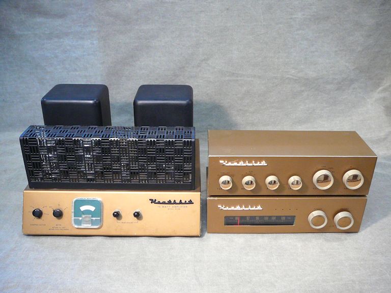
Here is my restored W-6M; the second photo shows it with my WA-P2 preamp and FM-3 tuner.

Finding a W-6M Amp
I got this amp in a trade with a fellow collector in 2013. I wasn't interested in replicating a
1950s hi-fi system, but I did need an audio amp to watch TV on my RCA
TM-10 color monitor.
The TM-10 monitor was used in TV studios and it was engineered to display the finest color picture possible in the
mid-1950s. Like the ground-breaking RCA CT-100 color TV,
it was based on the 15GP22 picture tube. Like most video monitors, it displays a picture with no audio.
Of course, I could use a modern audio amp, but the W-6M is a more fitting companion.
By joining these two best-of-breed components, I'll enjoy a 1950s television experience that few people could
have witnessed outside a broadcast studio.
General Description
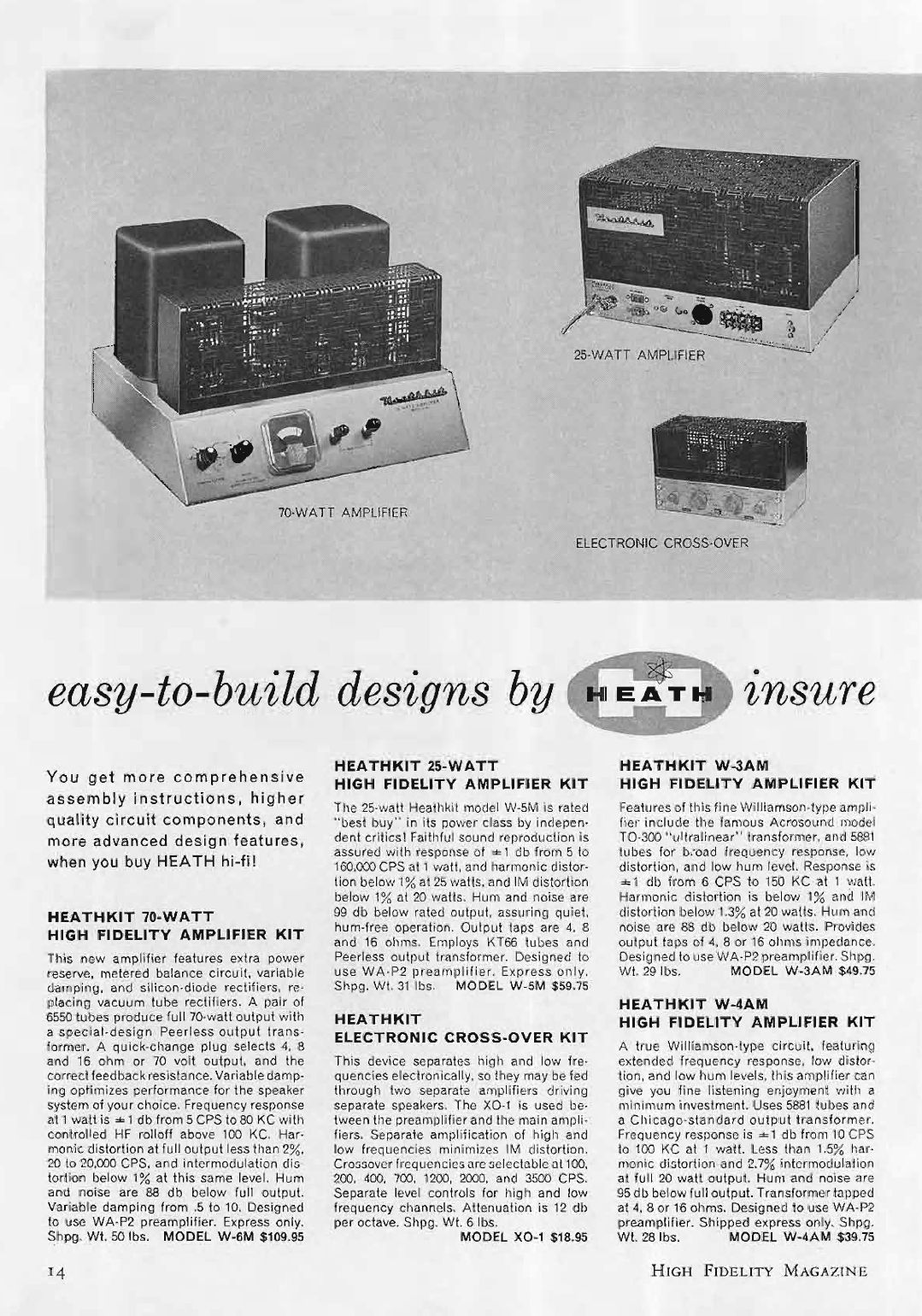
With a list price of $109.95, the W-6M was Heathkit's most powerful and expensive amplifier.
Below is an advertisement from the September, 1957 issue of High Fidelity:
The W-6M uses a pair of 6550 tubes to pump out 70 watts. It is a Williamson amplifier,
a type that was popular in high-fidelity circles during the 1950s and 1960s. You can find a brief
description of Williamson amps in a Wikipedia article.
More details appear in these
technical articles by the designer, D.T.N. Williamson.
Williamson amps are characterized by massive transformers. The W-6M weighs over forty pounds and
most of that weight lies in its big black transformers.
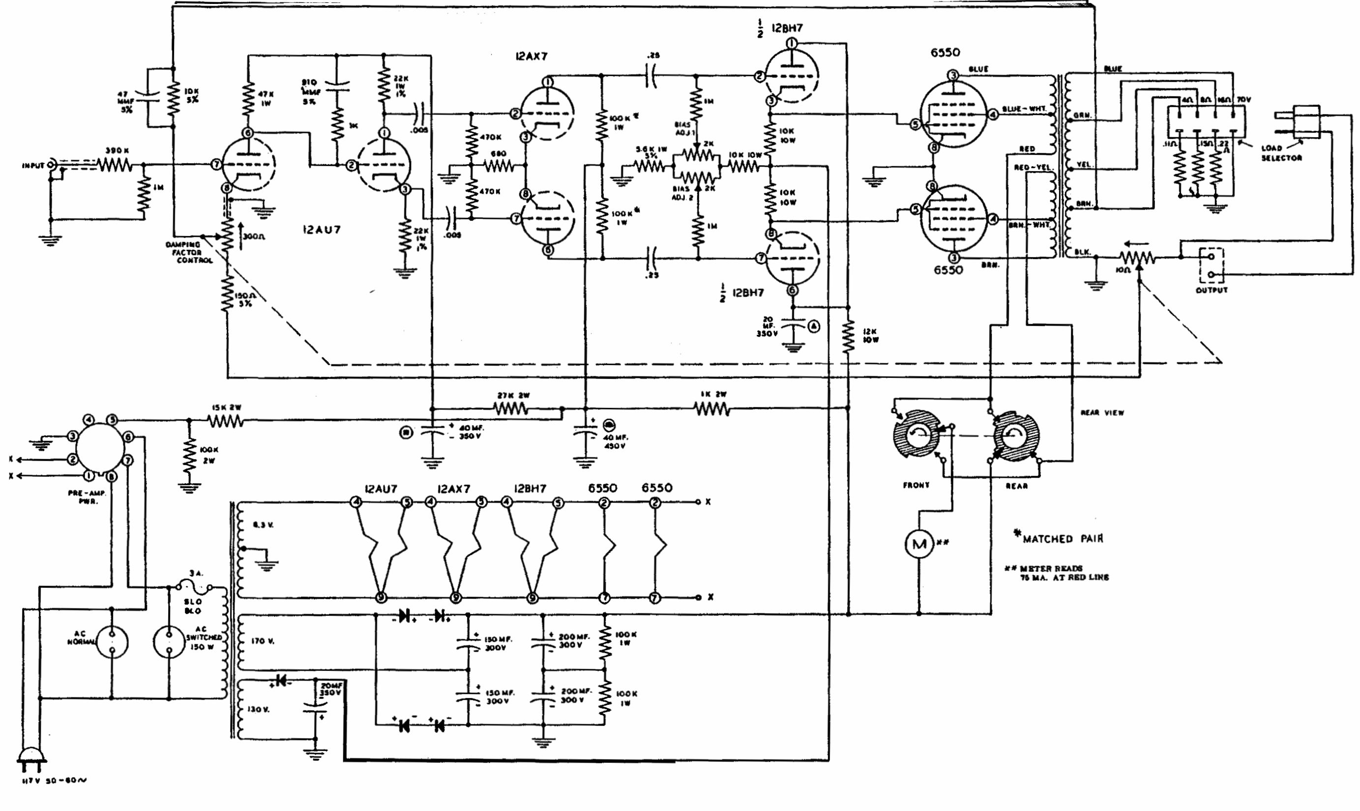
Click the next icon to view the first dozen pages of the W-6M owner's manual, which includes
the schematic diagram and many technical details.
By purchasing this amp in kit form, an audio enthusiast could save a considerable amount
of money. The comparable amp from McIntosh (model MC-60) retailed for over $200, double the
price of a W-6M.
Front Panel
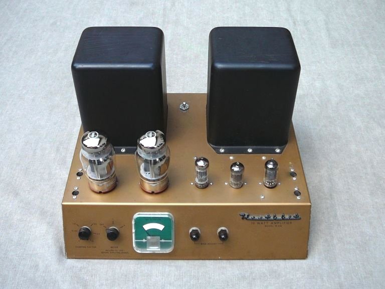
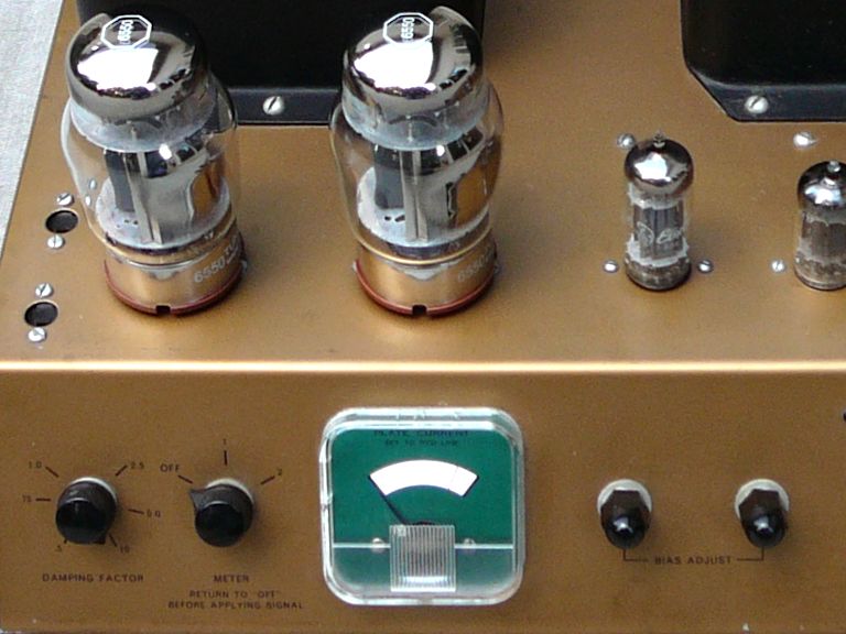
Here's another look at the W-6M with its tube cage removed. On the left are the
beefy 6550 tubes:
The front panel has four controls and a meter. From left to right, the controls are: the
damping factor control, the bias meter switch, and two bias adjusters (one for each
6550 tube).

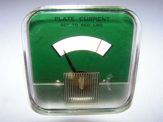
The bias meter lets you balance the bias voltages for the two 6550 output tubes,
a critical factor in a circuit of this type.
The bias switch has three positions (OFF-1-2) and the meter has a red line near
the top of its scale.

To set the bias for the first output tube, you set the switch
to 1 and use the first adjuster to bring the needle onto the red line. Then you switch to
2 and repeat the adjustment for the second tube. After the bias voltages are balanced at the
same level, you return the switch to its OFF position.
What is a Damping Control?
The amplifier's damping control was unfamiliar to me, so I asked for clarification on the Antique Radio
vintage audio forum,
eliciting these remarks from two forum members:
(From K7MCG): That damping control, like the similar control on the Fisher model 50, uses feedback
to adjust the output impedance of the amplifier, thus adjusting the damping on the motion
of a driven woofer. It can't do much to improve a good speaker, but can sometimes make a cheap
woofer sound much better. It can also partially compensate for the effects of too much speaker
cable resistance between the amplifier and woofer.
(From dberman51): Speakers of the 1950s varied as to how much amplifier damping they needed for best bass, so this
amplifier senses speaker current and uses it to drive the negative feedback loop. The damping
control determines how much current gets fed back. Modern speakers want maximum damping.
Another note describing this control appears on the last page of the W-6M manual.
Why No Volume Control?
If you're looking for a volume control or tone controls on this amp, don't bother. They don't
exist! As noted in the advertisement, this amp was designed to be used with a companion preamplifier,
the Heathkit WA-P2, which provides those functions and
also lets you switch among various inputs such as a phono turntable or FM radio tuner.
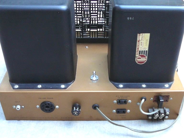
In this rear view, we see the various input/output connectors, including an eight-pin socket for
the cable that powers the WA-P2 preamp. The back of the output transformer sports a
Peerless label and serial number.

From left to right on the panel, we see the audio input jack, the eight-pin preamplifier power socket,
the fuse, and two 120-volt AC sockets (switched and unswitched)
for powering accessories such as a phono turntable. At far right are the speaker terminals and a four-position load selector that lets
you choose a speaker of 4, 8, or 16 ohms, as well as a 70-volt output.
The previous photo also shows a power switch between the two big black transformers.
This non-stock switch was added by the original owner.
The W-6M amp contains the power-supply circuitry needed to power itself and the WA-P2 preamp.
The On-Off switch is located on the preamp, but all power comes from the W-6M. In addition to
120-volt AC for the master power switch, the connecting cable
carries 6.3-volt AC for the preamp tube filaments and 300-volt DC for their plates.
Adding an auxiliary power switch to the amp lets you use it with an input other than the WA-P2 preamp.
In that case, you simply leave the WA-P2 power socket disconnected, but your alternate input
will have to provide whatever volume control or tone controls you desire.
Restoration
Let's get started with the restoration! Although sophisticated in design, the W-6M amp
is much simpler to restore than most of the radios and TVs I have tackled before. In this
discussion, I'll refer to the following schematic:

Getting Started
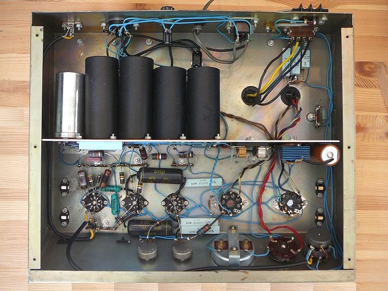
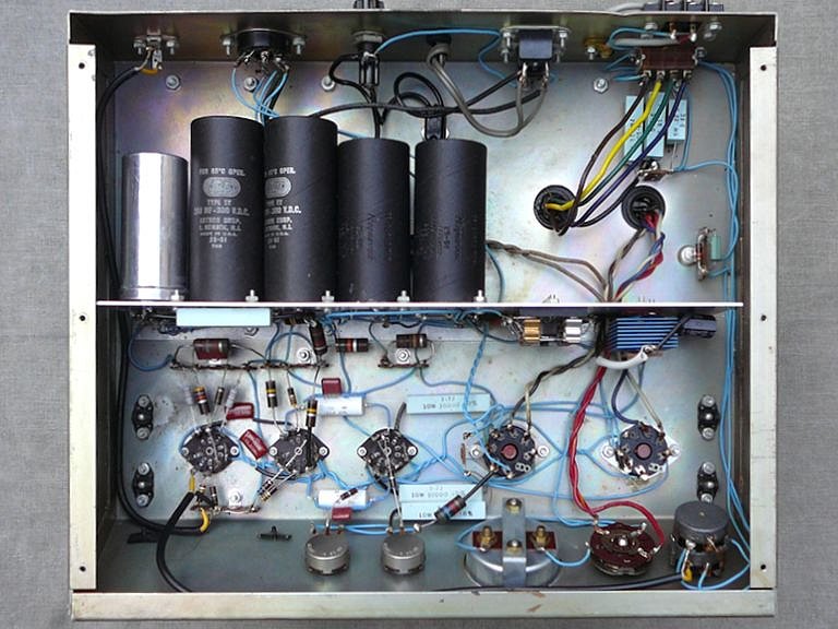
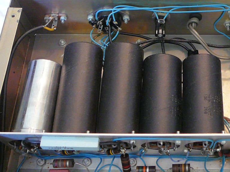
Here's a photo of the unrestored chassis:
In the upper compartment we see five large cans, which hold seven of the amp's eight electrolytic capacitors.
The lower compartment contains the signal circuitry and five solid-state power-supply rectifiers.
Our first glance is encouraging. This amp was assembled precisely, with tidy solder
joints and proper lead dress, exactly as shown in the building manual. In a high-fidelity
device, every component and wire is precisely located to prevent distortion or background hum.
The original owner did a very professional job!
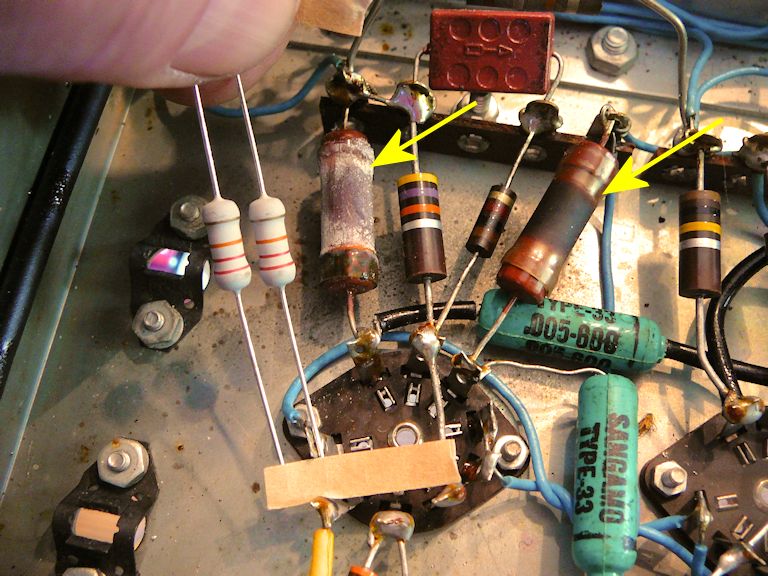
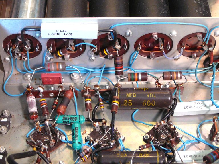
Looking more closely, I see evidence of overheating (or at least aging) in this pair of 22K resistors
on the 12AU7 tube.
These resistors are connected to the second section of the 12AU7 tube, which operates as a phase splitter, feeding the audio signal
to the 12AX7 push-pull amplifier stage. It's critical that they have the same value; Heathkit specified that they
have 1% tolerance, whereas most resistors in tube radios and TVs have a 20% tolerance. Even though the old resistors test
very close to the specified value, I'll replace them for peace of mind. I have selected a
pair of new resistors whose values measure well within 1%.
Finding no other surprises, I proceeded to do some clean-up and other preliminary tasks, such as
testing the tubes and cleaning the tube pins and sockets (see First Steps in Restoration.
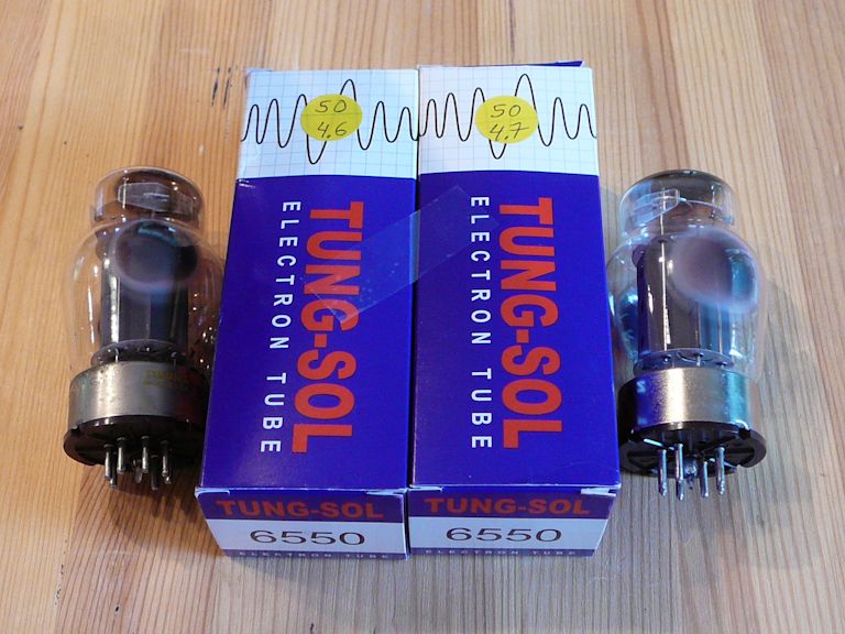
One of the old 6550 tubes was dead, so I ordered a new matched pair.

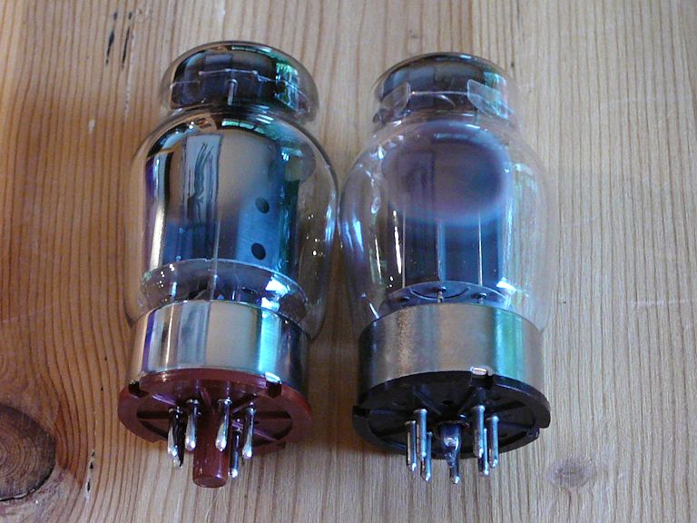
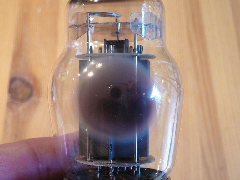
You normally can't tell much about a tube's condition from its outer appearance, but in this
case I can see that the old tubes racked up many hours of playing time. Note the
difference between the new and old tubes:


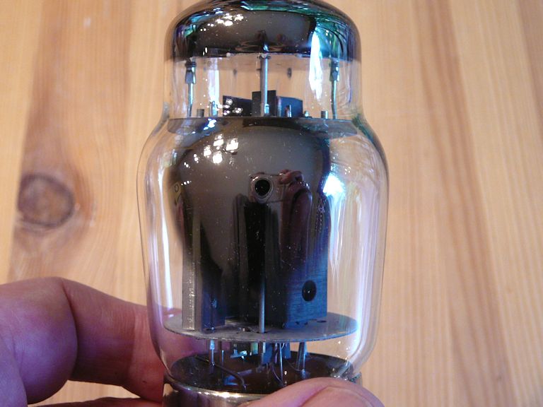
The new tube's "getter" is thick and silvery, while the old one is
dull and depleted, nearly transparent. The getter is a thin deposit of metal (often
barium) inside the tube's glass envelope. Its purpose is to adsorb any stray molecules
of gas that were left behind when the tube was evacuated during manufacture. As more and
more molecules are neutralized during the tube's working life, the getter changes appearance.
Don't conclude too much from appearances, however.
A depleted-looking getter isn't necessarily a death sentence: a tube that has been used
long enough to fade its getter may still have plenty of life left. Both of my old tubes
looked superficially similar, but one of them tested with very strong emission, and I would
have been willing to use it indefinitely—if I could find another one that matched its characteristics.
If I had bought only one new tube, there's a chance that the strong old one would have worked
acceptably with it, but it was simpler to buy a new matched pair that's guaranteed to work.
Replacing Capacitors
As noted in my recapping article, capacitor replacement is a routine part of restoring
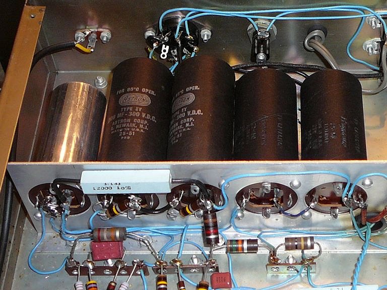
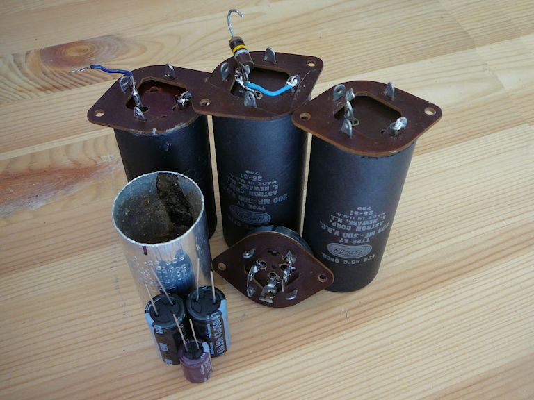
every vintage tube device. I'll begin, as usual, with the big electrolytics. Of these five cans, the one on
the left contains three caps and the others contain one cap per can.

Electrolytic can bases are sometimes hard to access, but these are
out in the open.

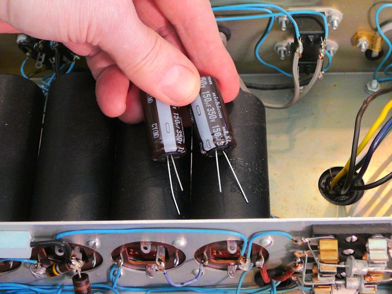
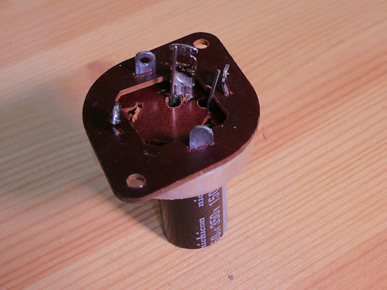
I'll warm up with a couple of simple ones. These two cans on the right end of the row each
contain a single 150-mfd cap and the replacements will easily fit inside after
I hollow out the cans.

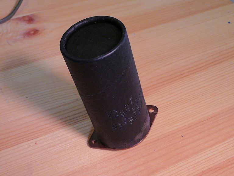
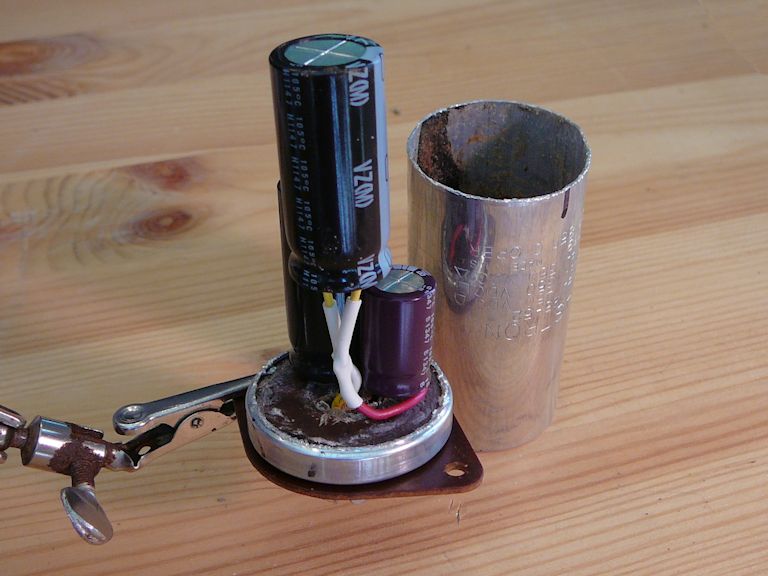
In the next photos, I have removed the cardboard cover, sawed open and emptied the old aluminum can,
installed the new cap, epoxied the metal can to the base and refastened the cover. (You can read more details of
this "restuffing" process in various articles which have links in my recapping article.)


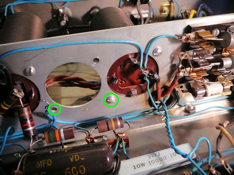
Bada-bing, bada-boom! The restuffed can has been installed.

Notice the empty base hole in the previous photo.
Before installing the fresh can, I removed its neighbor to make a little elbow room.
When all of the cans were in place, my fingers couldn't reach behind to reinstall the innermost mounting nut (note the
circled screw holes in the photo). When it was time to install the final can, I temporarily taped the tiny nut and washer to the eraser end of a pencil and sneaked them in that way.

Fast forward: in the next photo, I have restuffed three more cans. The remaining can will hold three caps.

Wiring three caps onto the base takes a little patience, but there's still
ample room to epoxy the empty can back on.

The next photo shows the fresh cans back at home.
This project is more than half done, and the remaining work involves small, easy-to-reach
components. While I had those associated resistors disconnected, I checked
them to make sure their values hadn't drifted out of tolerance. After testing the remaining resistors,
I proceeded to replace the handful of small paper (and plastic-coated paper) capacitors.
At this stage I gave the amp a cautious trial, bringing up the power on a variac and metering the current draw
to make sure it didn't exceed a safe level. It worked! I also checked the voltages on all of the tubes,
comparing them to the W-6M manual's voltage chart. All of them were in the right ballpark.
Upgrading the Rectifiers
Although the old rectifiers are working for the moment, it's prudent to replace them. Old selenium rectifiers
are notoriously unreliable, and three of the four silicon rectifiers have already been replaced,
showing that the originals had a high failure rate.
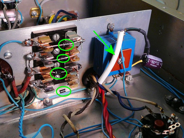
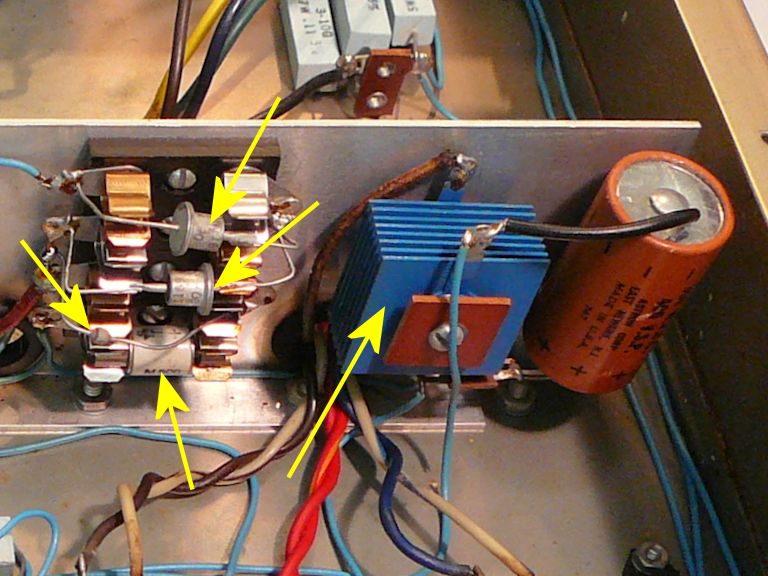
In the next photo, yellow arrows identify all five rectifiers.

The big blue component is a selenium rectifier. Next to it is the last remaining electrolytic
capacitor. In the four-rectifier stack at left, only the cylindrical
one at the bottom is original. A technician has already wired newer rectifiers (two "top hats"
and one bead-style) around the snap-in terminals for three of the fuse-like originals.
This photo shows how I used type 1N4007 silicon diodes to replace all of the old rectifiers.
The old selenium unit has been taken out of the circuit, but I used one of its terminals as
an anchor point, enclosing the new diode in a white sleeve.
Restoration Complete
After replacing nineteen components, my W-6M project is finished. These photos show
the chassis before and after restoration.
Although the amp's voltages
looked reasonable in the earlier trial, I rechecked the voltage on every pin of every
tube, as well as the supply points at the electrolytic capacitors and on the power connector,
comparing them to the voltage chart in the manual. Now the measurements look better than
ever. I should be able to play this amp for many hours without worrying that a
marginal old component will conk out.
One Last Tweak
Before buttoning up the W-6M, I made a little change, disconnecting the 120-volt AC line from
the WA-P2 preamp power connector and routing it to the amplifier's onboard power switch.
Now, when the amp and preamp are used together, they are turned on at the amp rather than the preamp.
(The power cable still supplies filament and plate voltage to the preamp, as always.)
This change silenced a slight background hum resulting from that connection and
it lets me use another input such as an iPod without being tied to the preamp.
You can read more about the hum issue in my WA-P2 article.
Final Thoughts
I haven't finished restoring my TM-10 color monitor—that was the original reason to get this
amp, remember?—but in the meantime I enjoy using my W-6M with its matching preamp and FM tuner:
Paired with a good speaker like one of my Klipsch Quartets, you'd be surprised how good a
1950s-era hi-fi system can sound!
|